 Charles Lakins
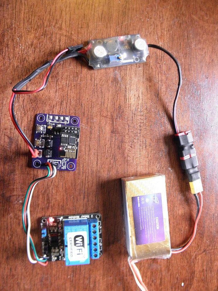
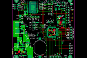
I plan to make the final pcb board large enough to mount the relay on also, for the sake of production cost this version for testing was done, but links will remain in my published section for oskpark orders after the large version is produced
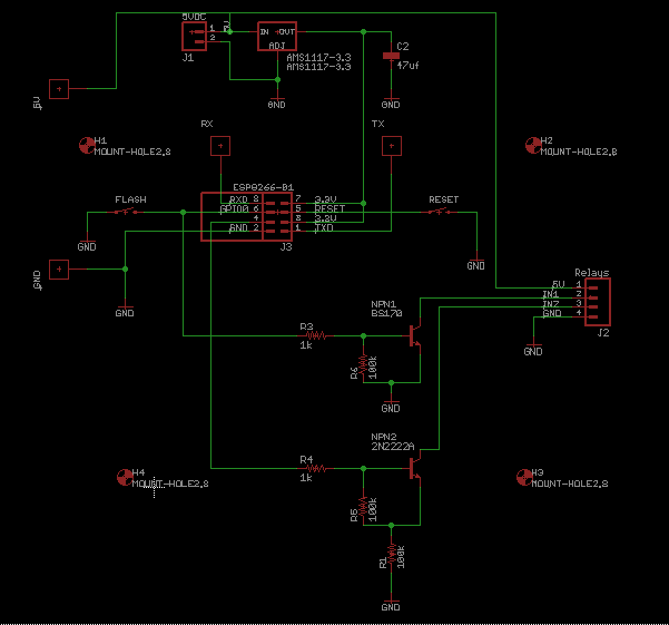
Schematic: (swapped npn1 to BS170 mosfet)
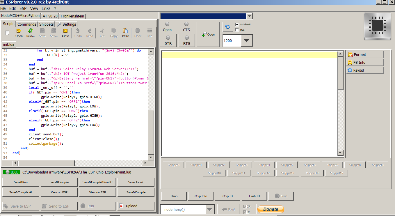
Code so far (without display support)"
wifi.setmode(wifi.STATION)
wifi.sta.config("ssid","weppassword")
print('\nSolar PV Controller - ESP8266 Server v1b\n')
tmr.alarm(0, 1000, 1, function()
if wifi.sta.getip() == nil then
print("Connecting to AP...\n")
else
ip, nm, gw=wifi.sta.getip()
macAdd = wifi.sta.getmac();
print("IP Info: \nIP Address: ",ip)
print("Netmask: ",nm)
print("Gateway Addr: ",gw,'\n')
print("Mac Addr: ",macAdd,'\n')
tmr.stop(0)
end
end)
Relay1 = 0
Relay2 = 2
gpio.mode(Relay1, gpio.OUTPUT)
gpio.mode(Relay2, gpio.OUTPUT)
srv=net.createServer(net.TCP)
srv:listen(80,function(conn)
conn:on("receive", function(client,request)
local buf = "";
local _, _, method, path, vars = string.find(request, "([A-Z]+) (.+)?(.+) HTTP");
if(method == nil)then
_, _, method, path = string.find(request, "([A-Z]+) (.+) HTTP");
end
local _GET = {}
if (vars ~= nil)then
for k, v in string.gmatch(vars, "(%w+)=(%w+)&*") do
_GET[k] = v
end
end
buf = buf.."<h1> Solar Relay ESP8266 Web Server</h1>";
buf = buf.."<h2> IOT Project irun4fun 2016</h2>";
buf = buf.."<p>Battery Bank <a href=\"?pin=ON1\"><button>Power ON</button></a> <a href=\"?pin=OFF1\"><button>Power OFF</button></a></p>";
buf = buf.."<p>Solar Array <a href=\"?pin=ON2\"><button>Power ON</button></a> <a href=\"?pin=OFF2\"><button>Power OFF</button></a></p>";
local _on,_off = "",""
if(_GET.pin == "ON1")then
gpio.write(Relay1, gpio.HIGH);
elseif(_GET.pin == "OFF1")then
gpio.write(Relay1, gpio.LOW);
elseif(_GET.pin == "ON2")then
gpio.write(Relay2, gpio.HIGH);
elseif(_GET.pin == "OFF2")then
gpio.write(Relay2, gpio.LOW);
end
client:send(buf);
client:close();
collectgarbage();
end)
end)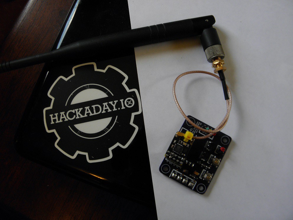


 Bharbour
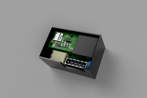
 Nicolò
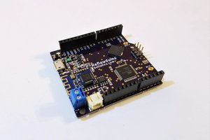
 Timothy Woo
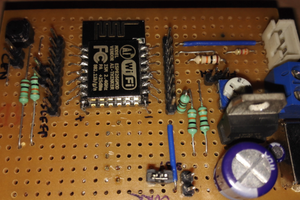
 Rishi
Rishi
Yes, sorry, I miss the webserver picture.
the idea was to put all in a double socket box without transformer:
220---->12----->5----->3,3 ( tremendous contraption with 3 1N4007 diode), looking something compact.
waiting for future developments
all the best iw0hjz