 M. Bindhammer
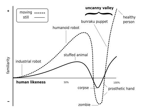
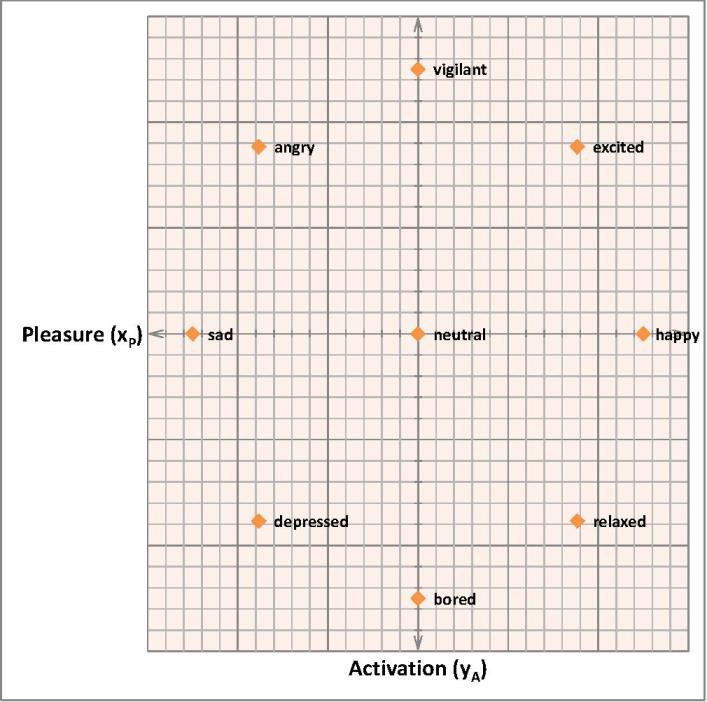
Humanoid robots walk through an uncanny valley, a hypothesis stated by Masahiro Mori that as the appearance of a robot is made more human, some observers' emotional response to the robot will become increasingly positive and emphatic, until a point is reached beyond which the response quickly becomes that of strong revulsion.
Following plot speaks volumes:
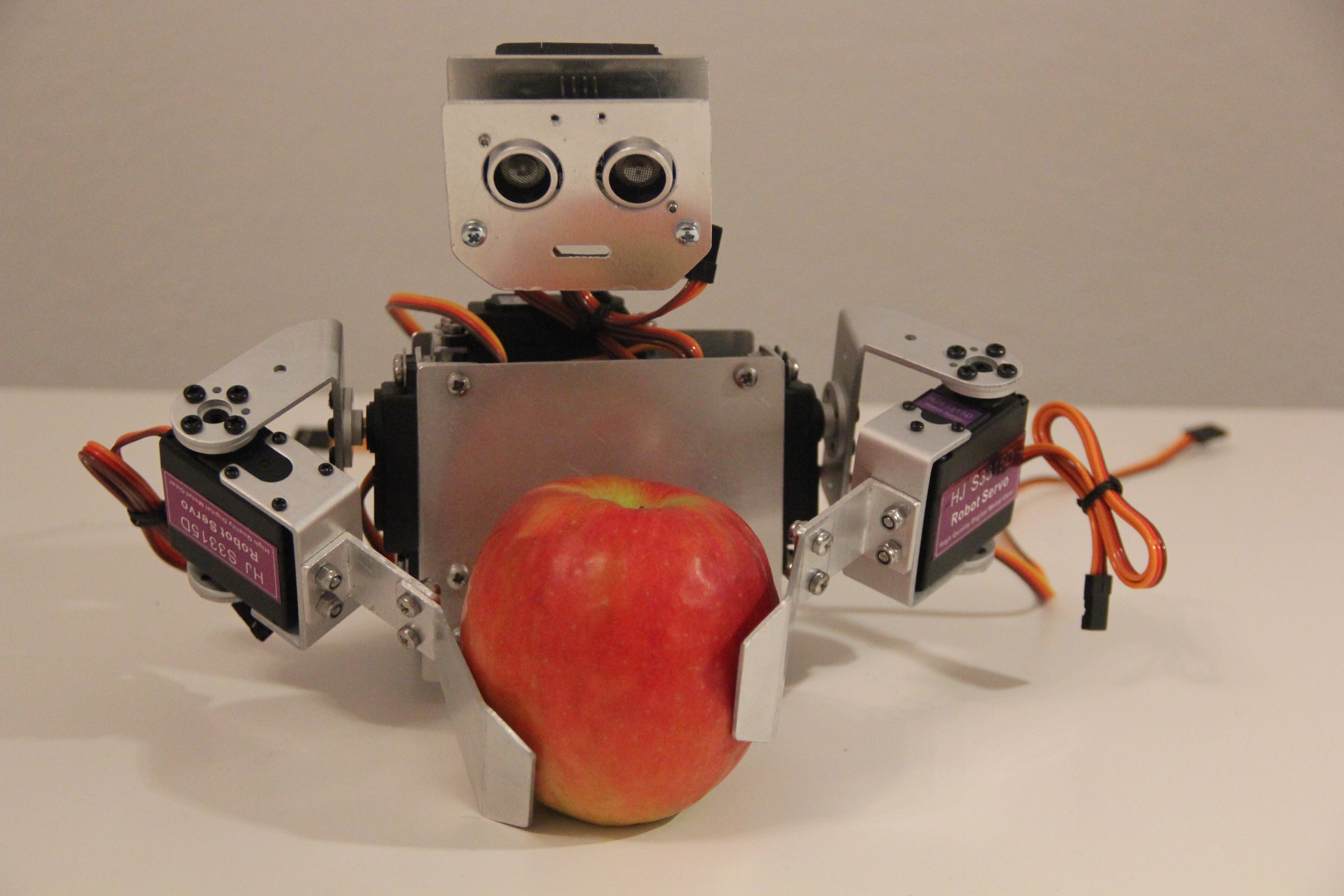
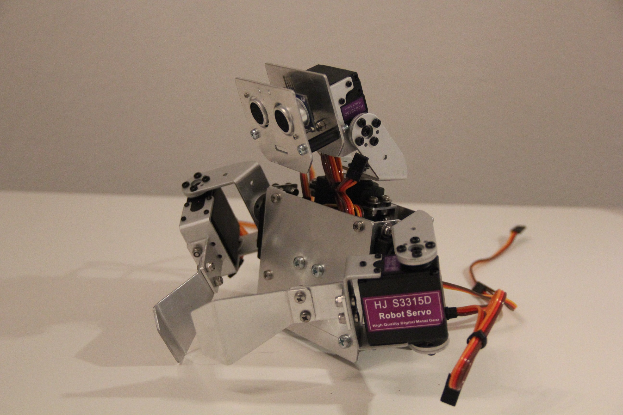
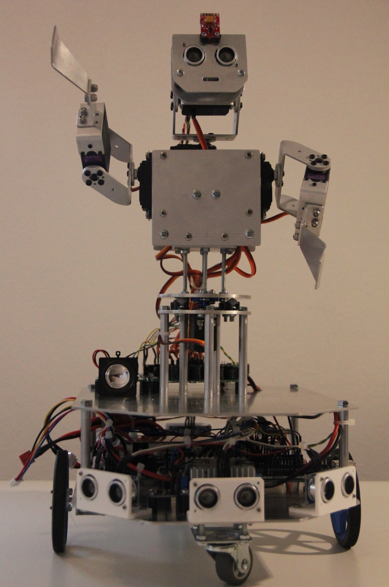
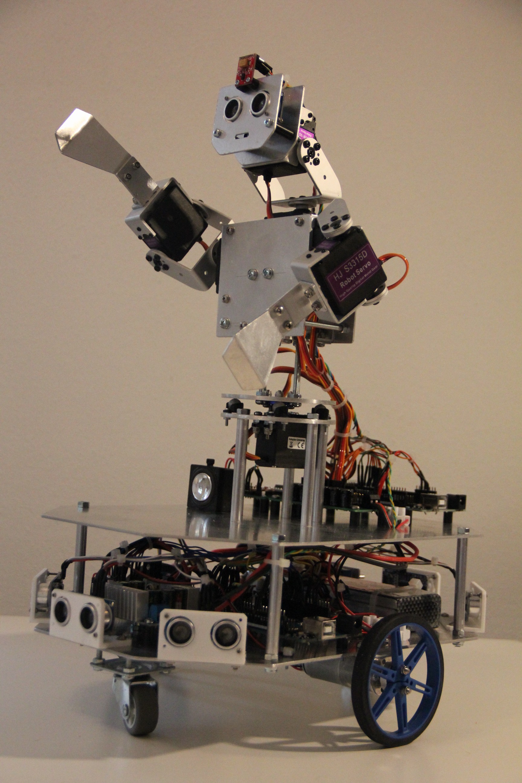
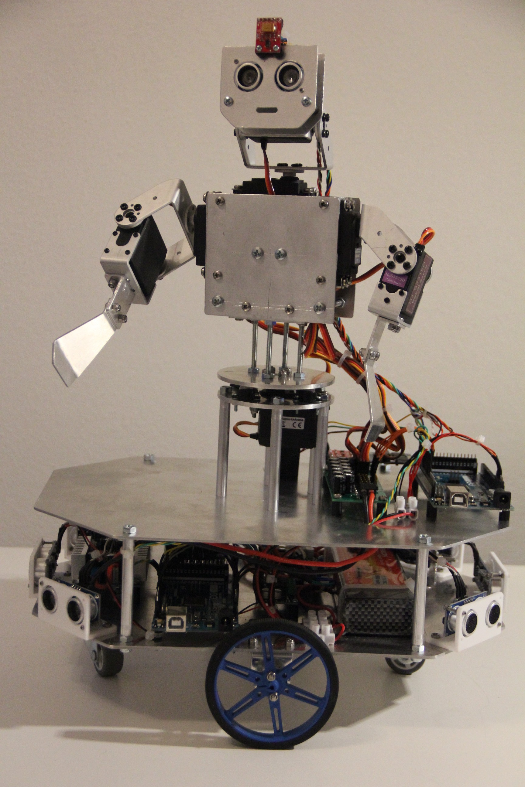
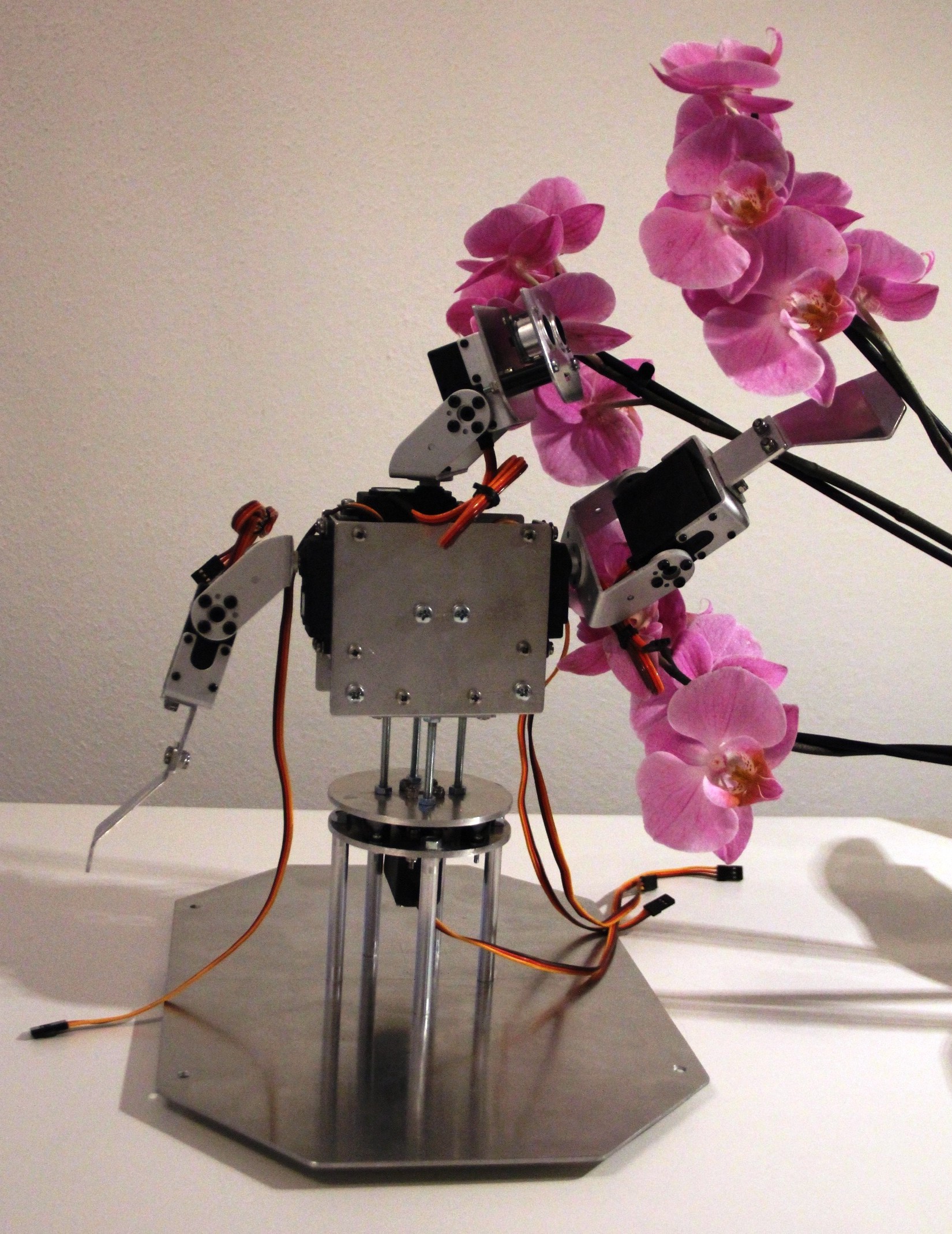
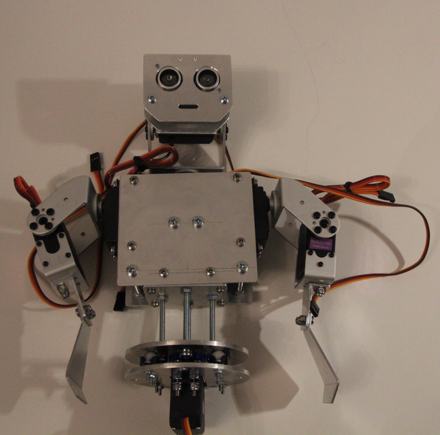
That is why I put a lot of thoughts in Murphy's design, not making it too human like or worse - look like a zombie. Revised the design a few times. Not a replica of the human body, just loosely based. For the moment I will leave you here, providing you just some technical data, design goals, a basic system design and impressions of the robot during its development in this project details chapter. Please check out the project logs for more...So far:
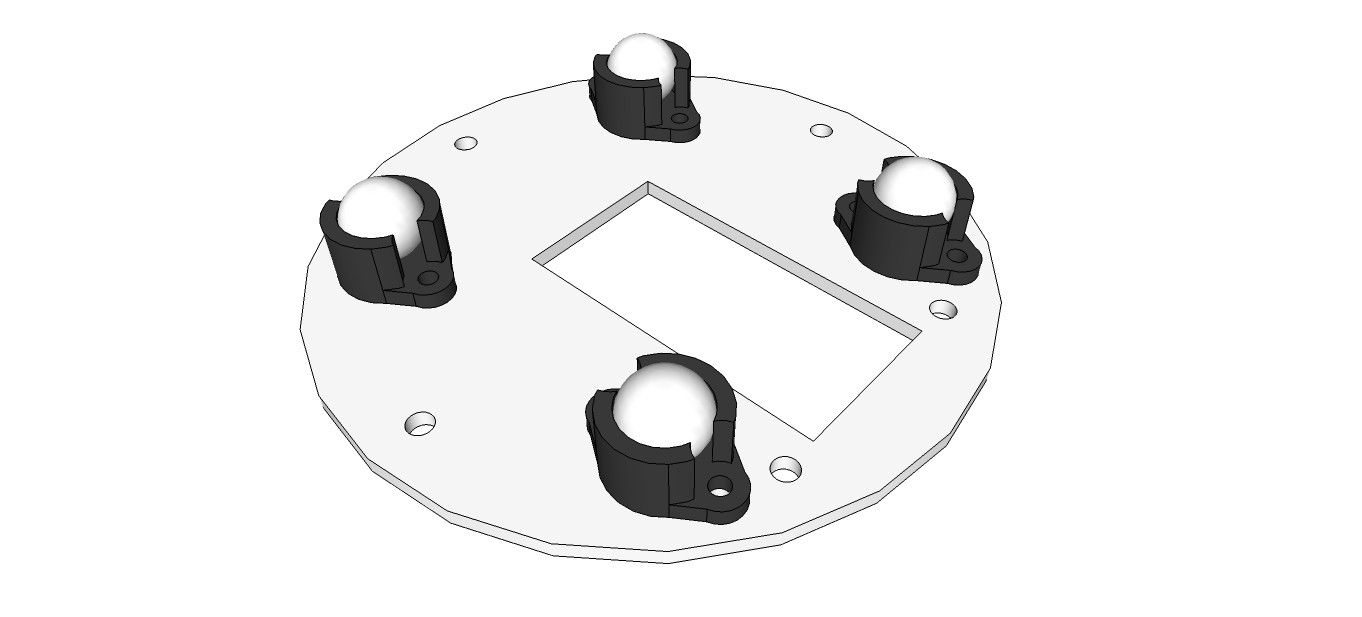
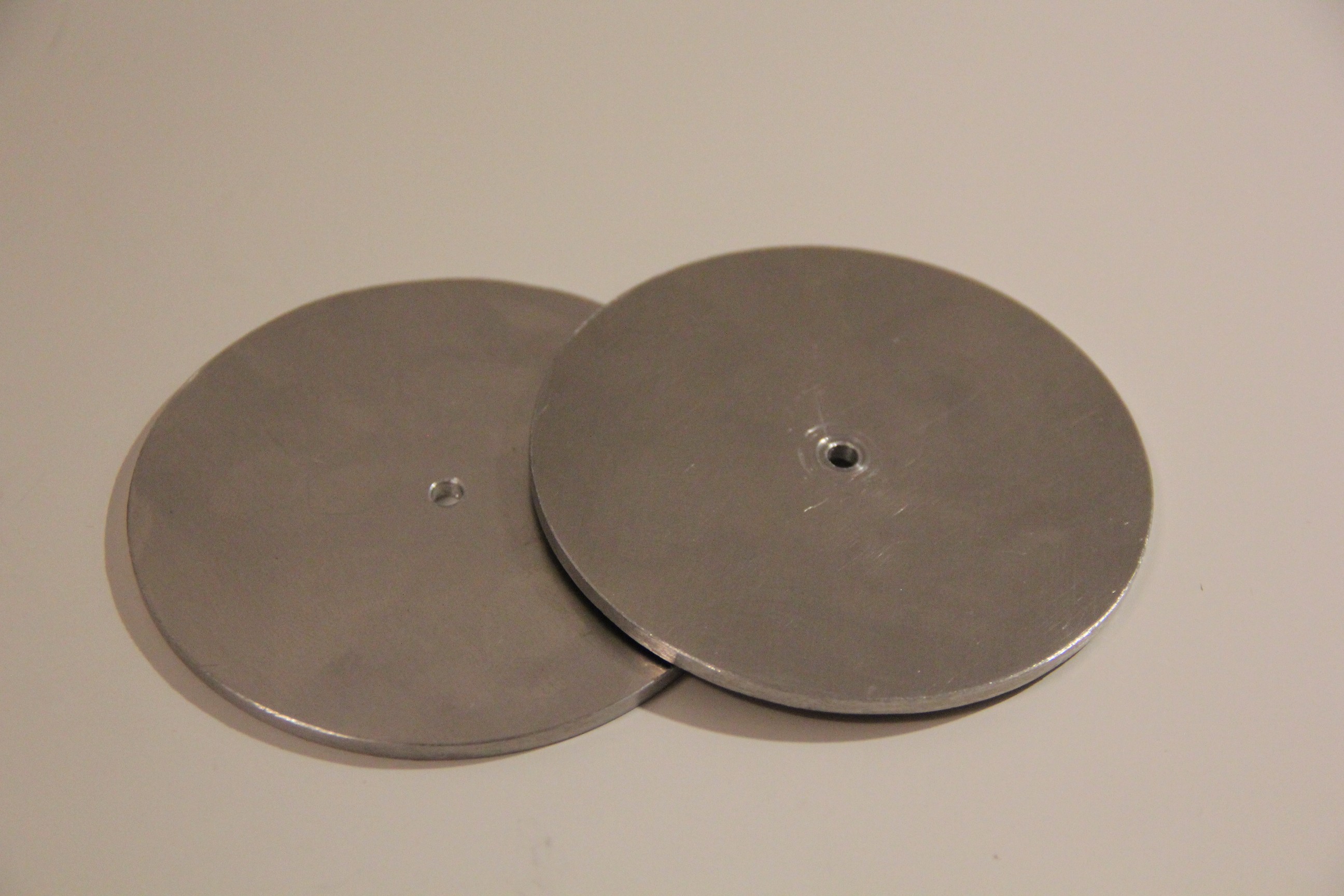
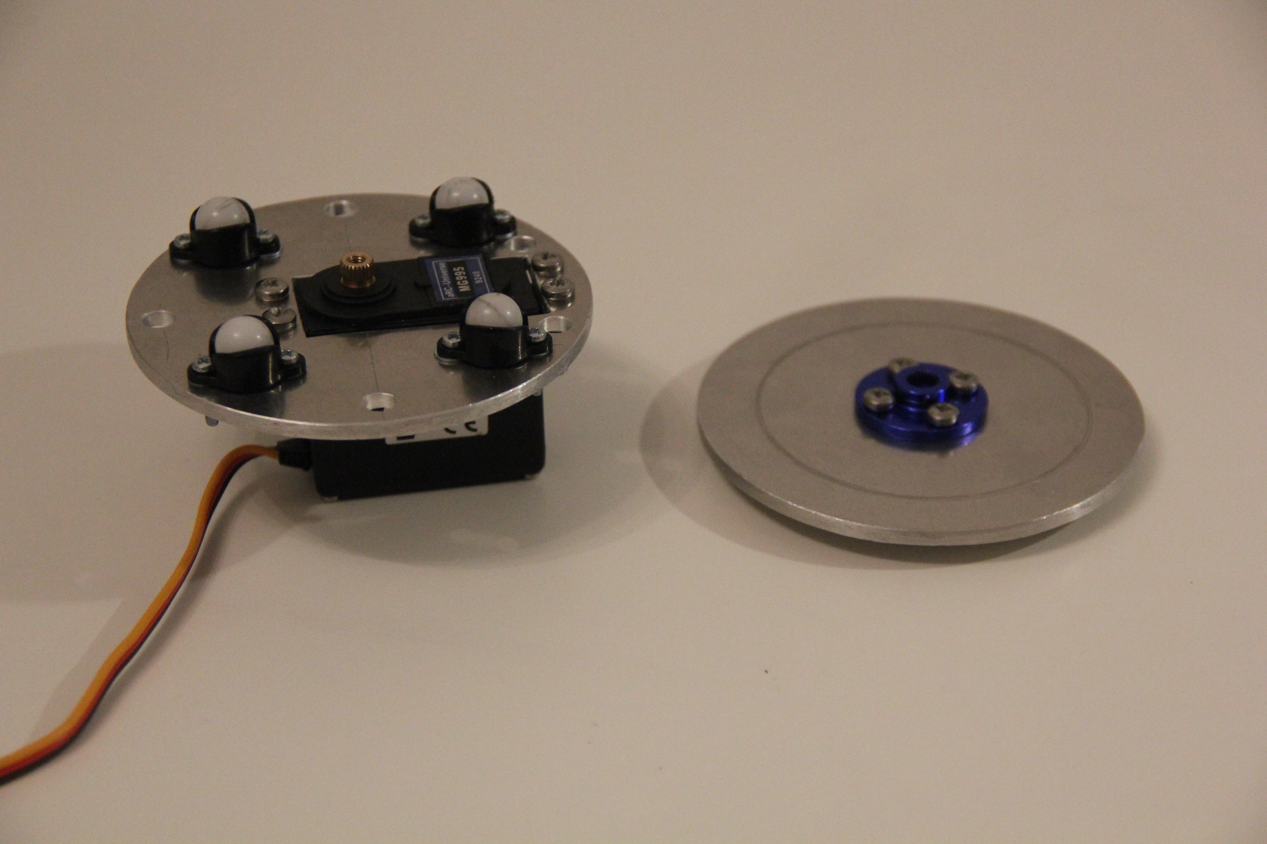
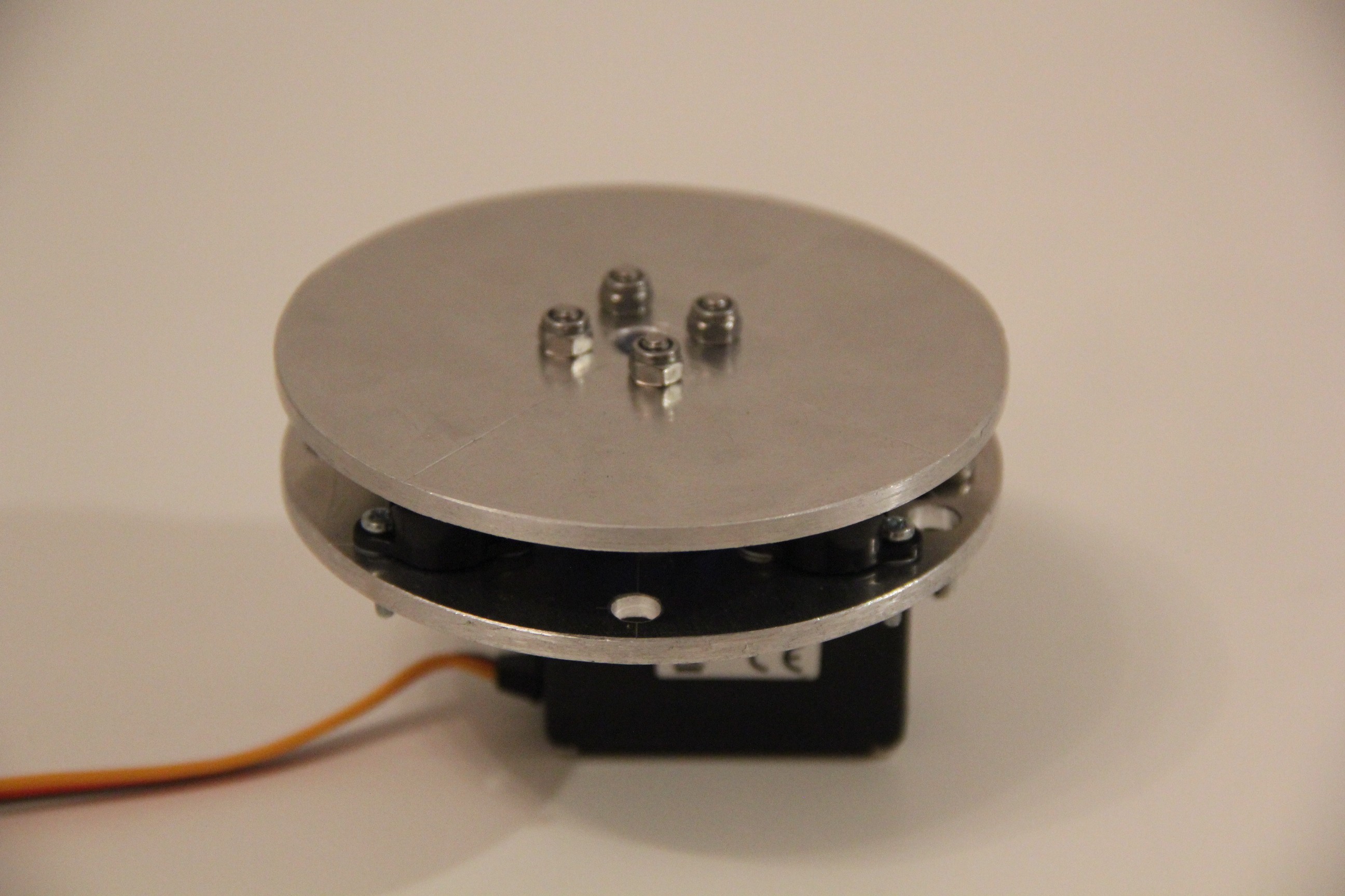
- Building the base rotate unit
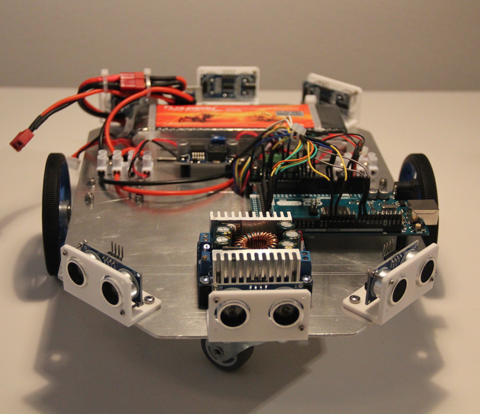
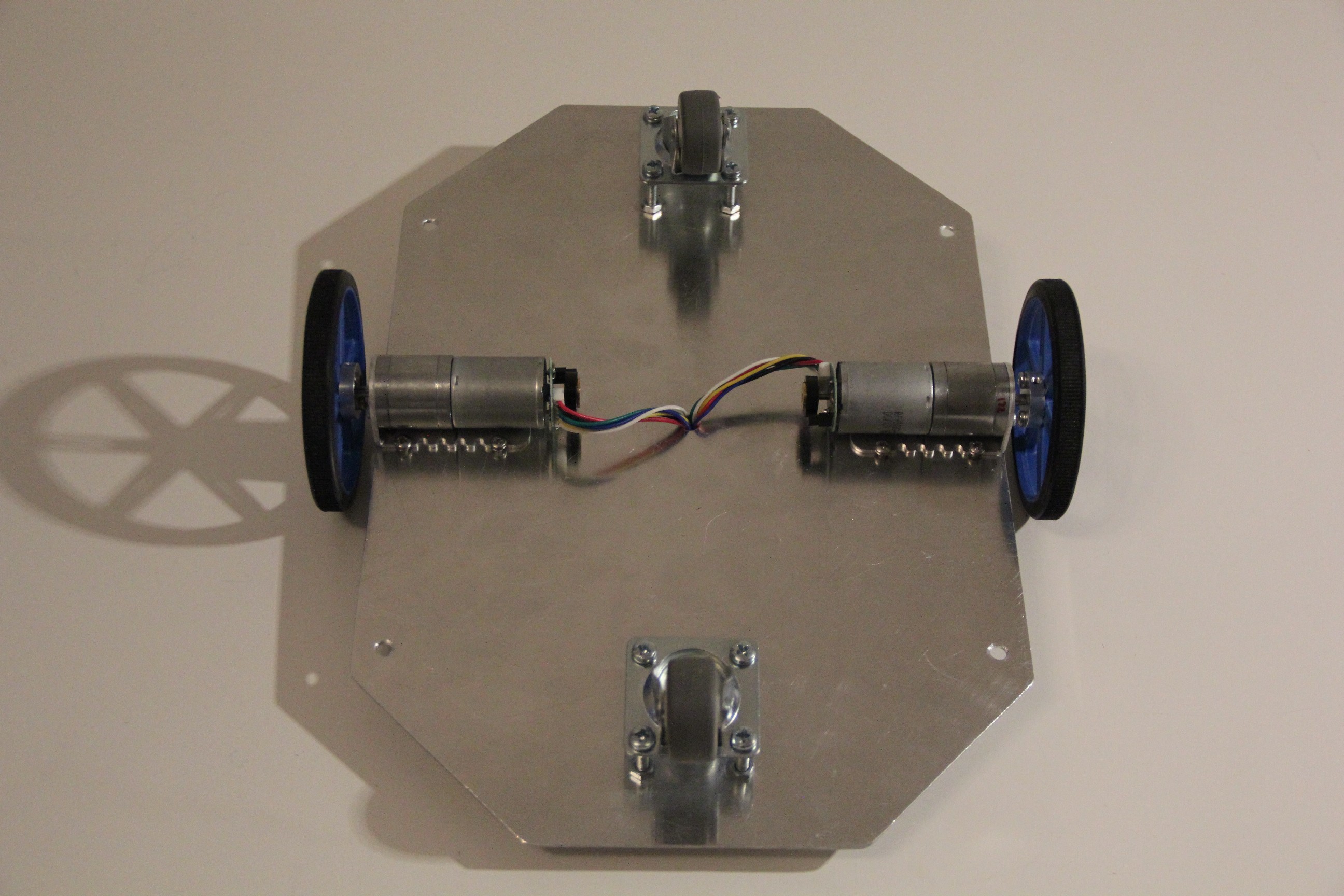
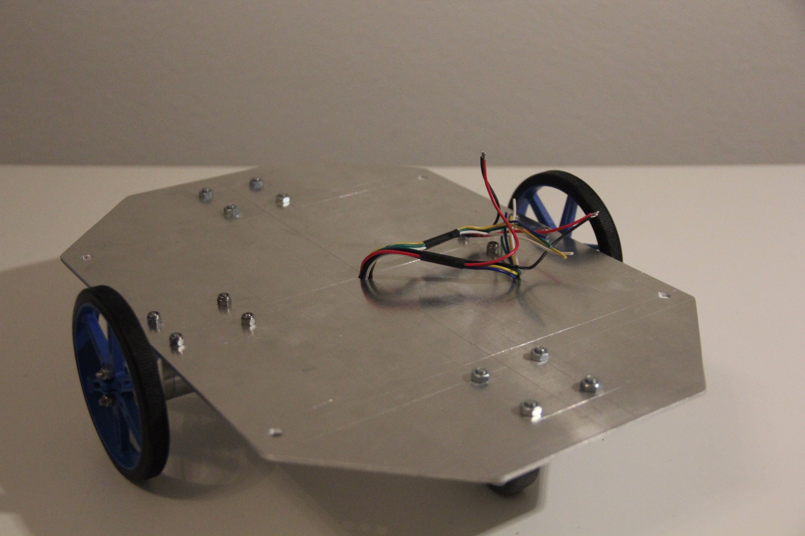
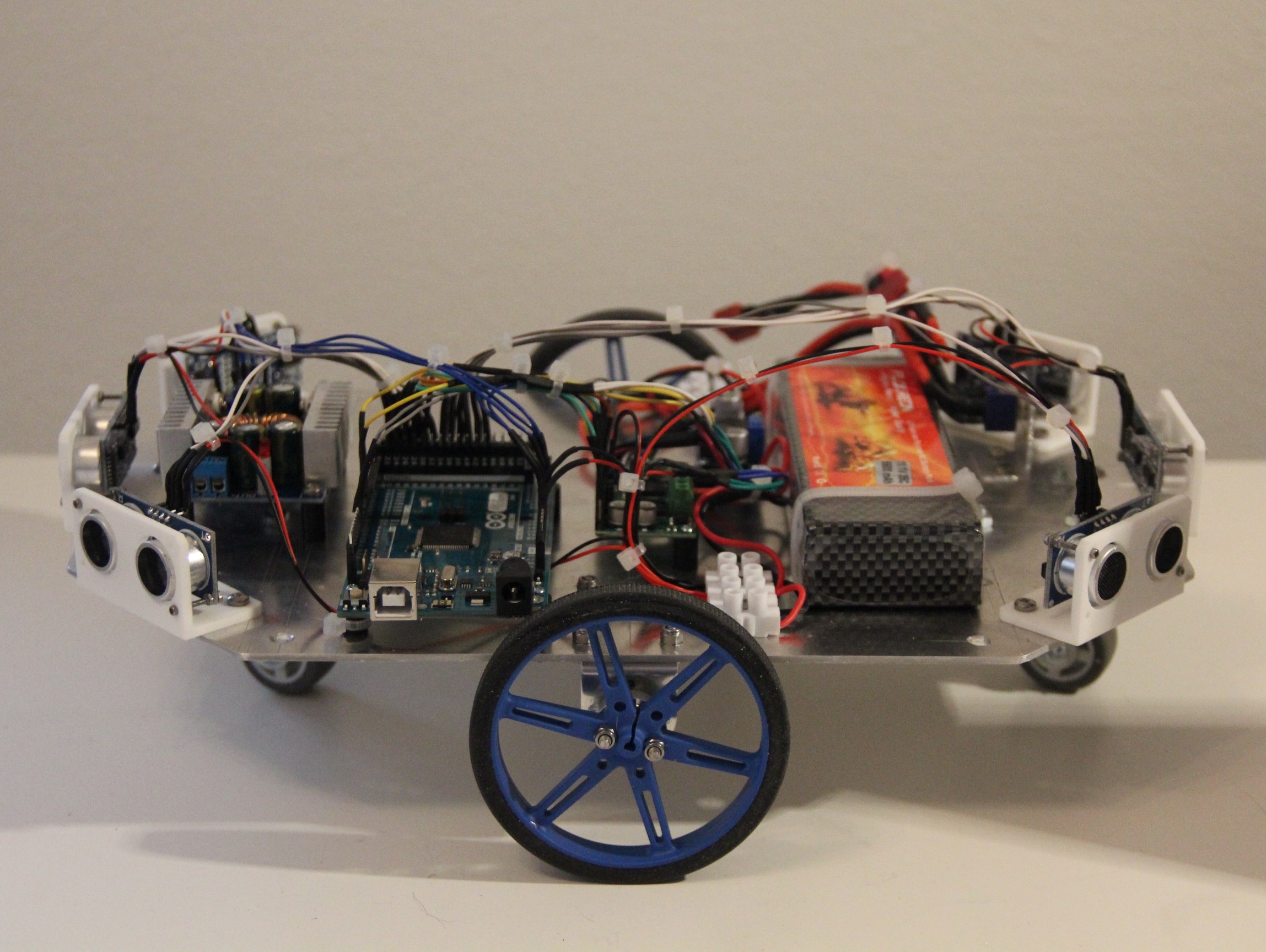
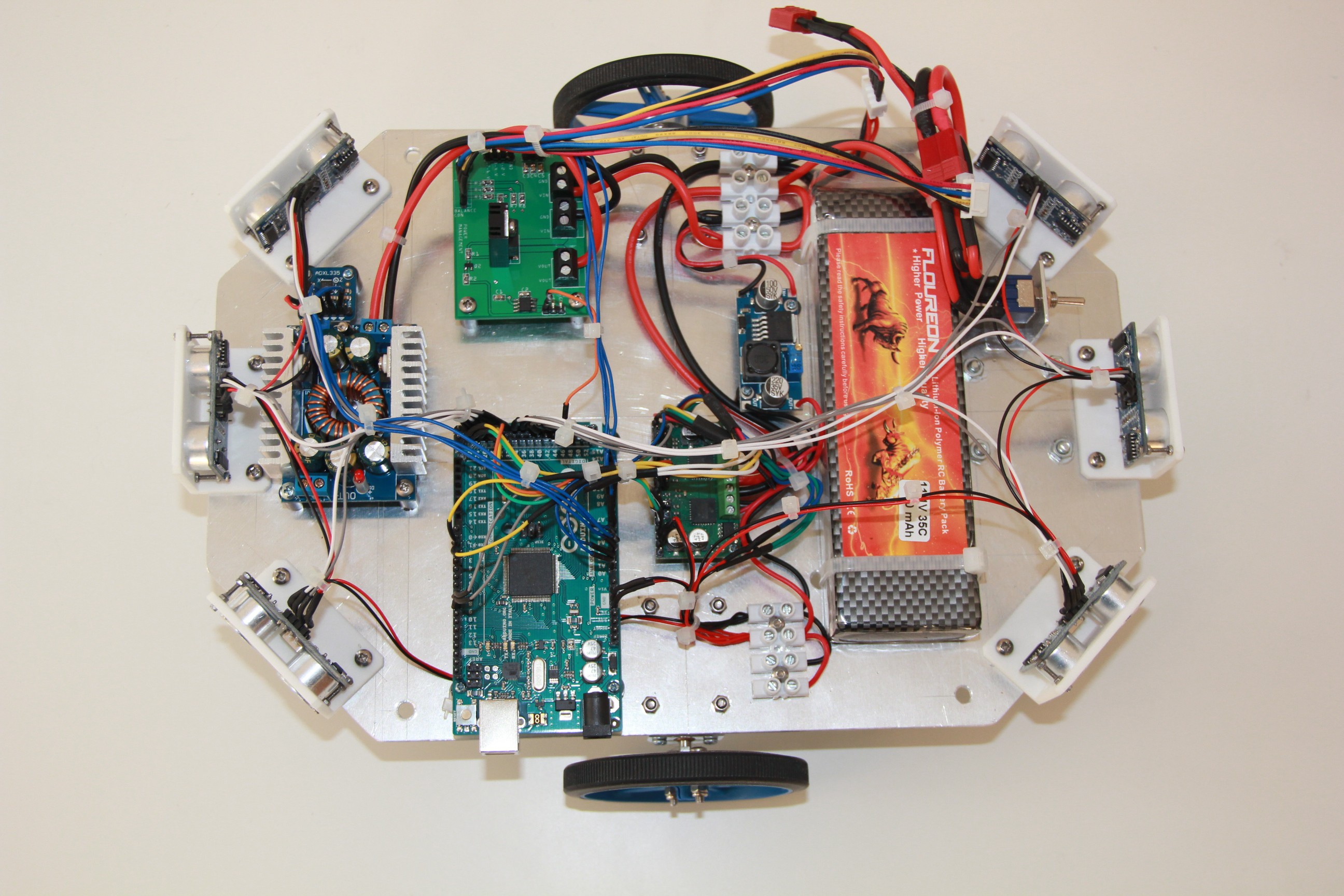
- Building the differential wheeled robot base
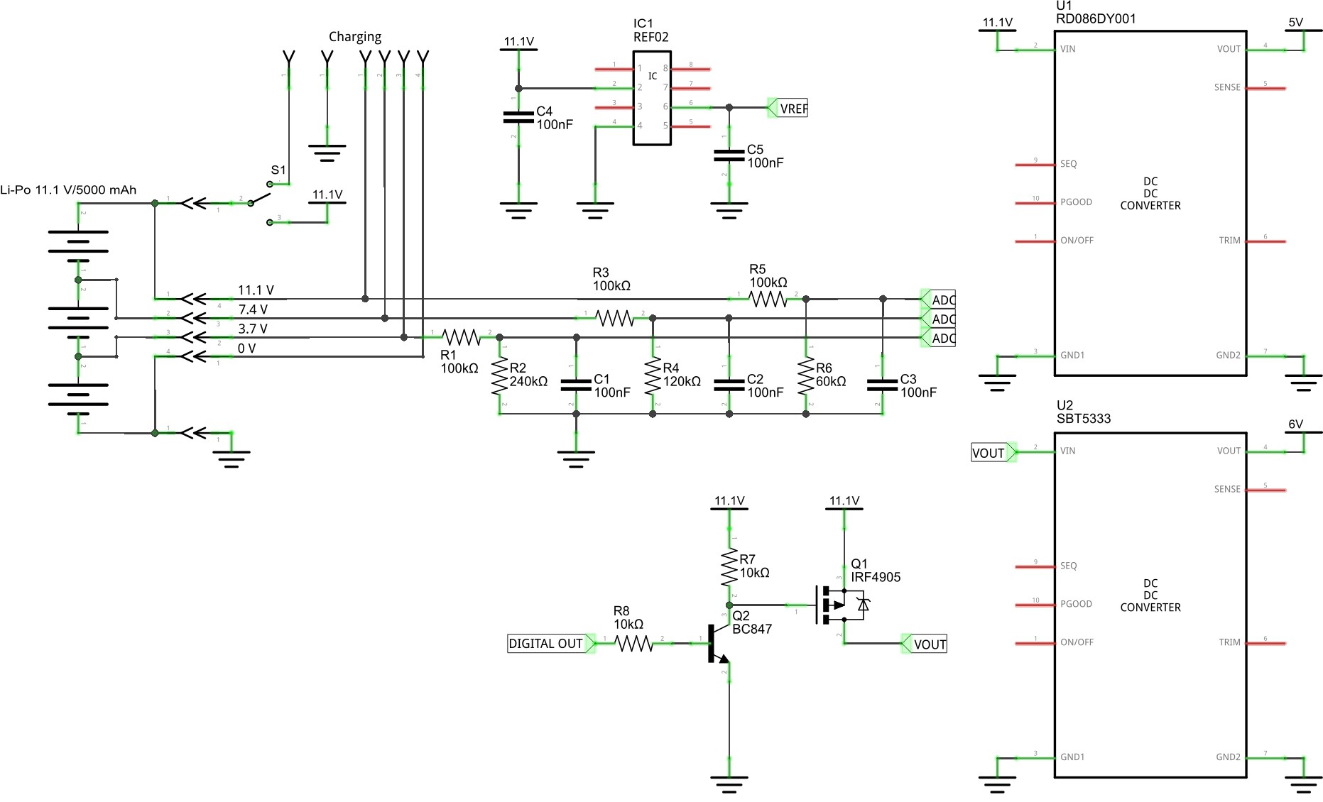
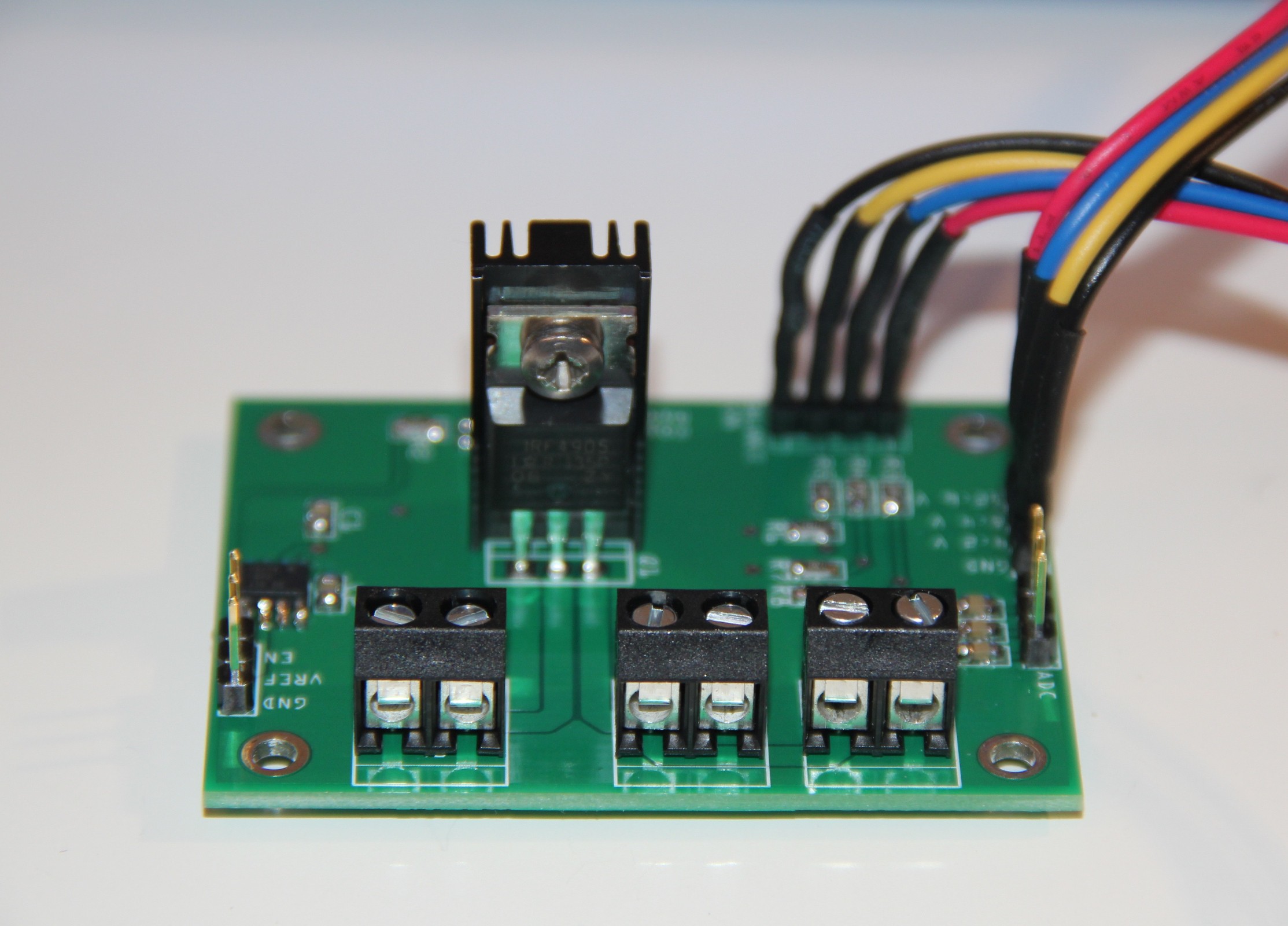
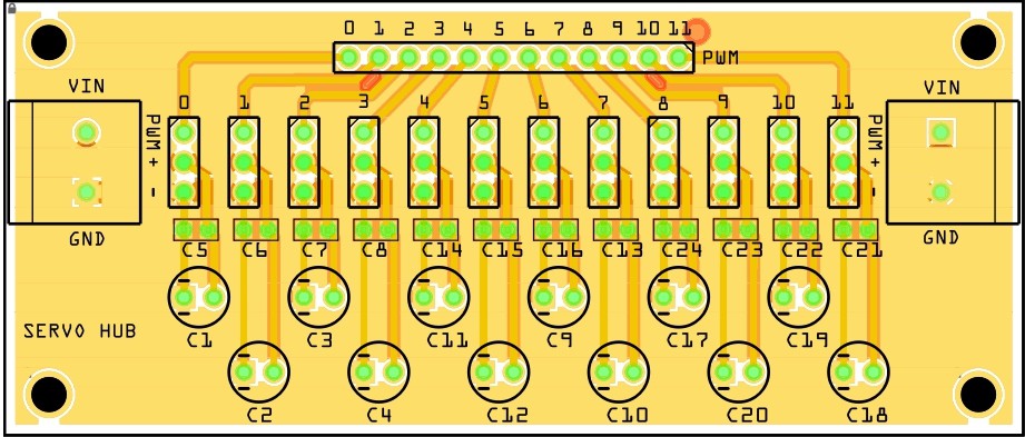
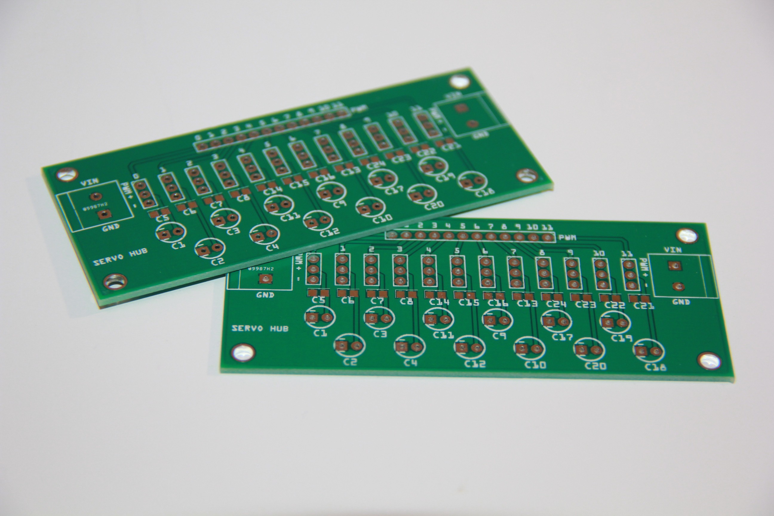
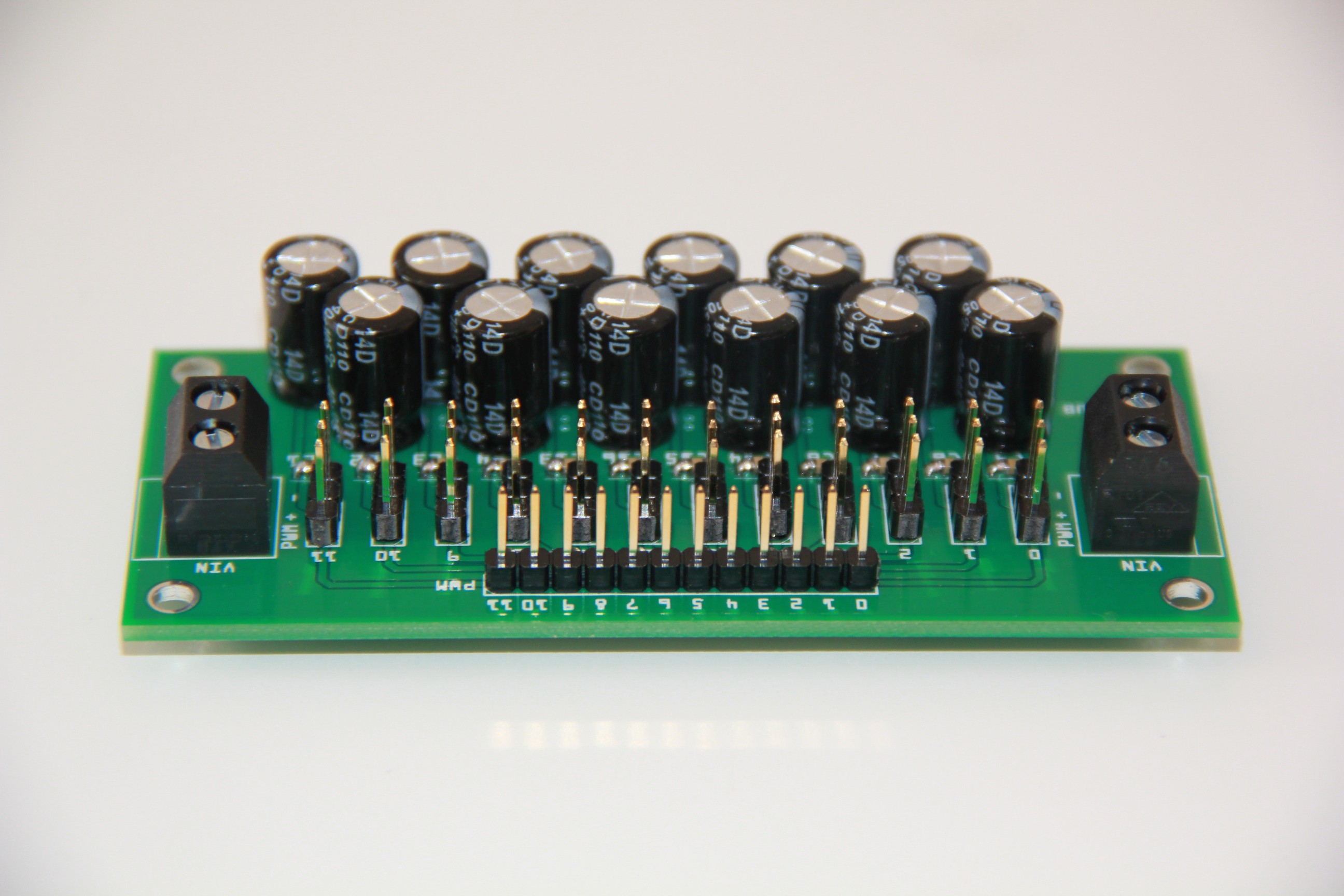
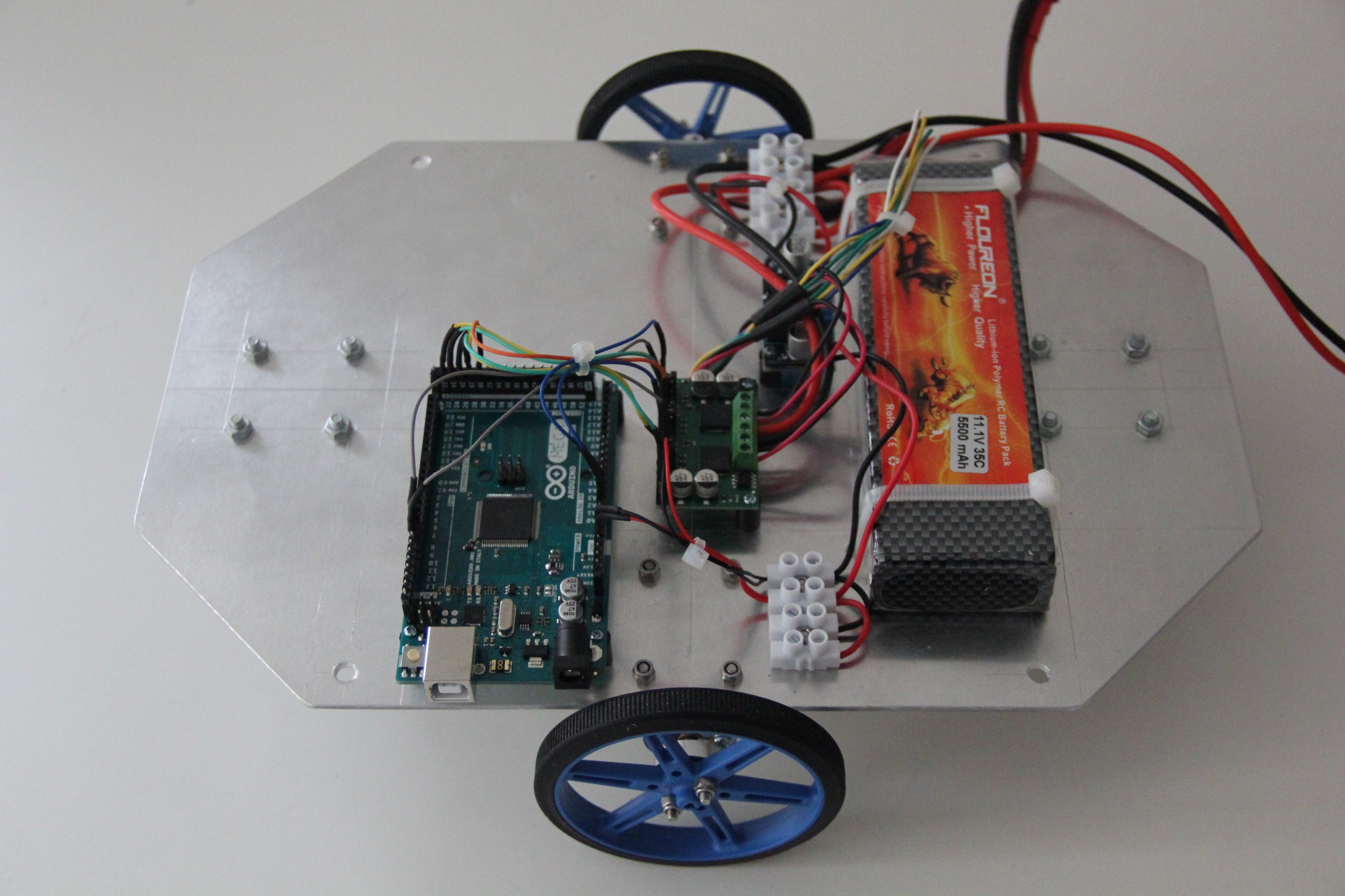
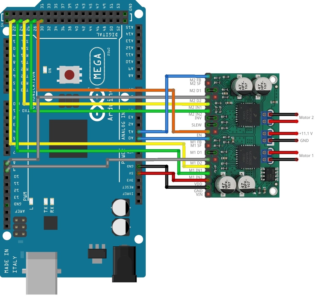
- Power management
- Machine learning
- Emotional agent
- Language center
- Markov chains
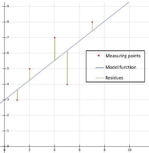
- Simple linear regression
- Working on Murphys torso
Murphy's specs
Height: 60 cm
Weight: 3 kg
Drive system: DC gear-motors with encoders
Actuators: 2 x 2 DOF robot arm, 1 x 2 DOF head, 1 x base rotate unit
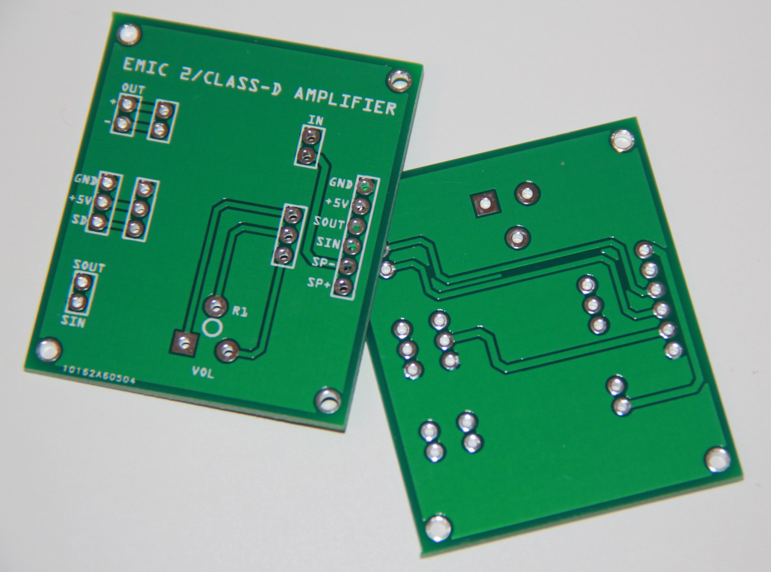
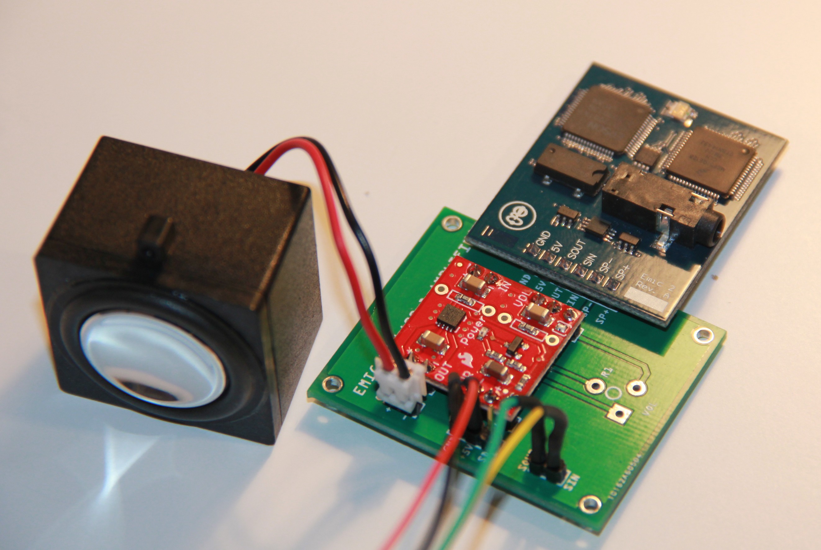
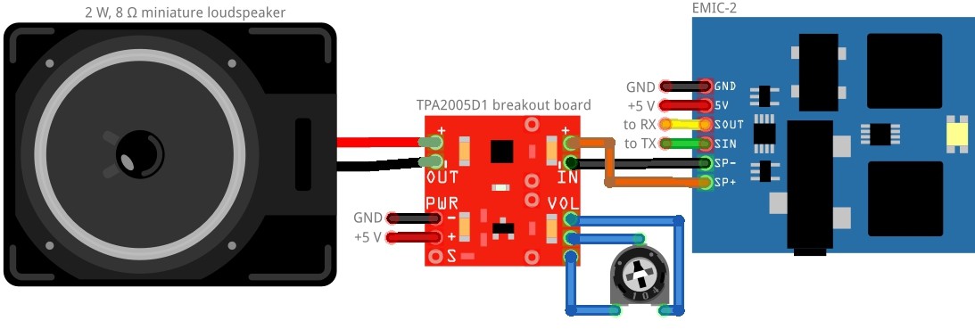
Output devices: 1 x Loudspeaker 2 W, 8 Ω
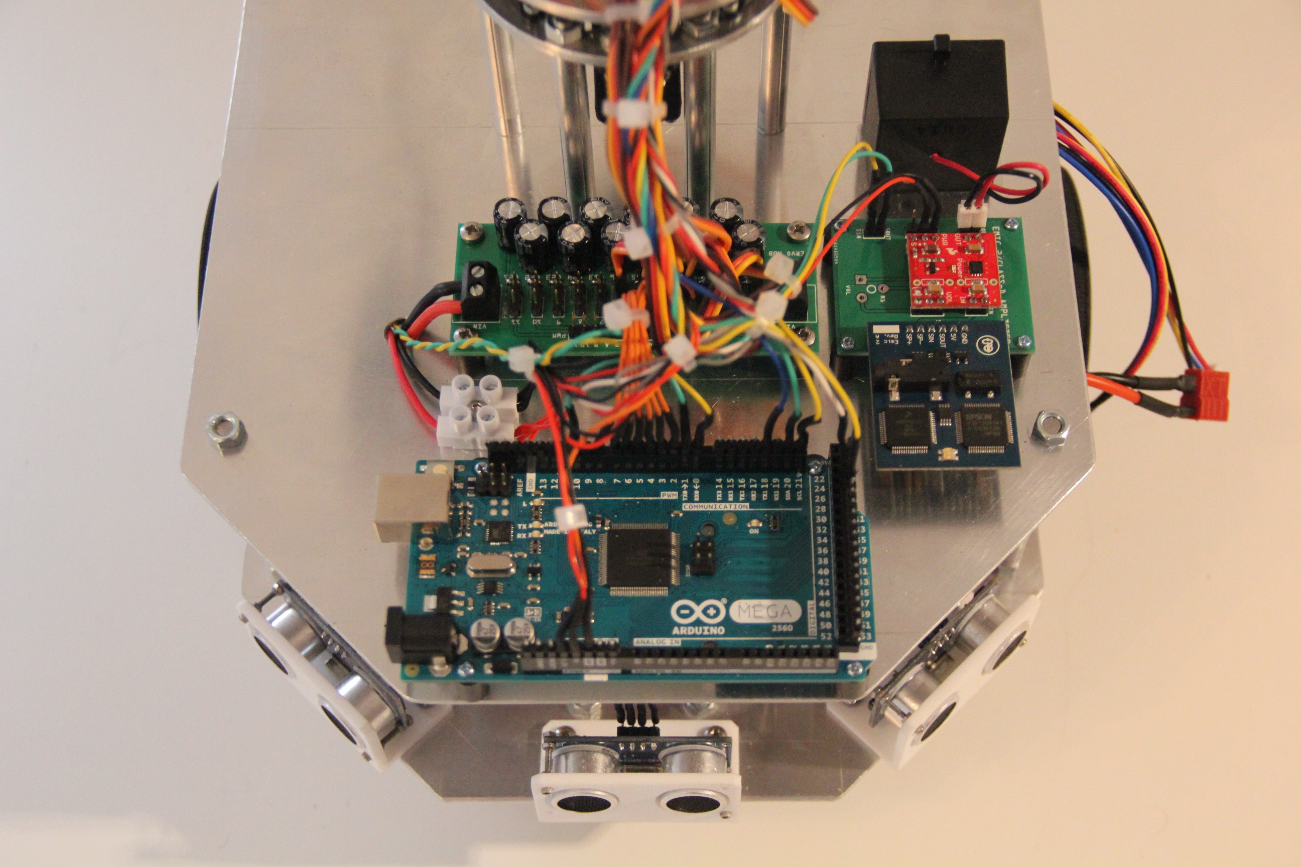
CPU's: 2 x Arduino Mega, 1 x Raspberry Pi
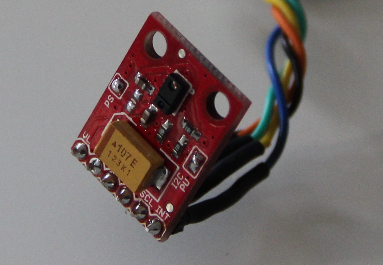
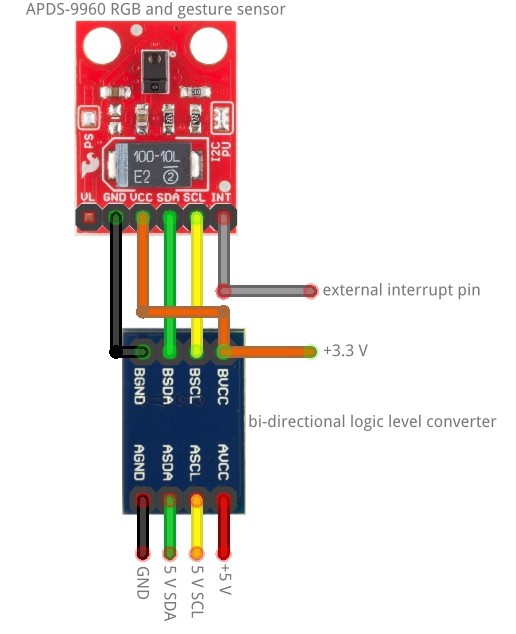
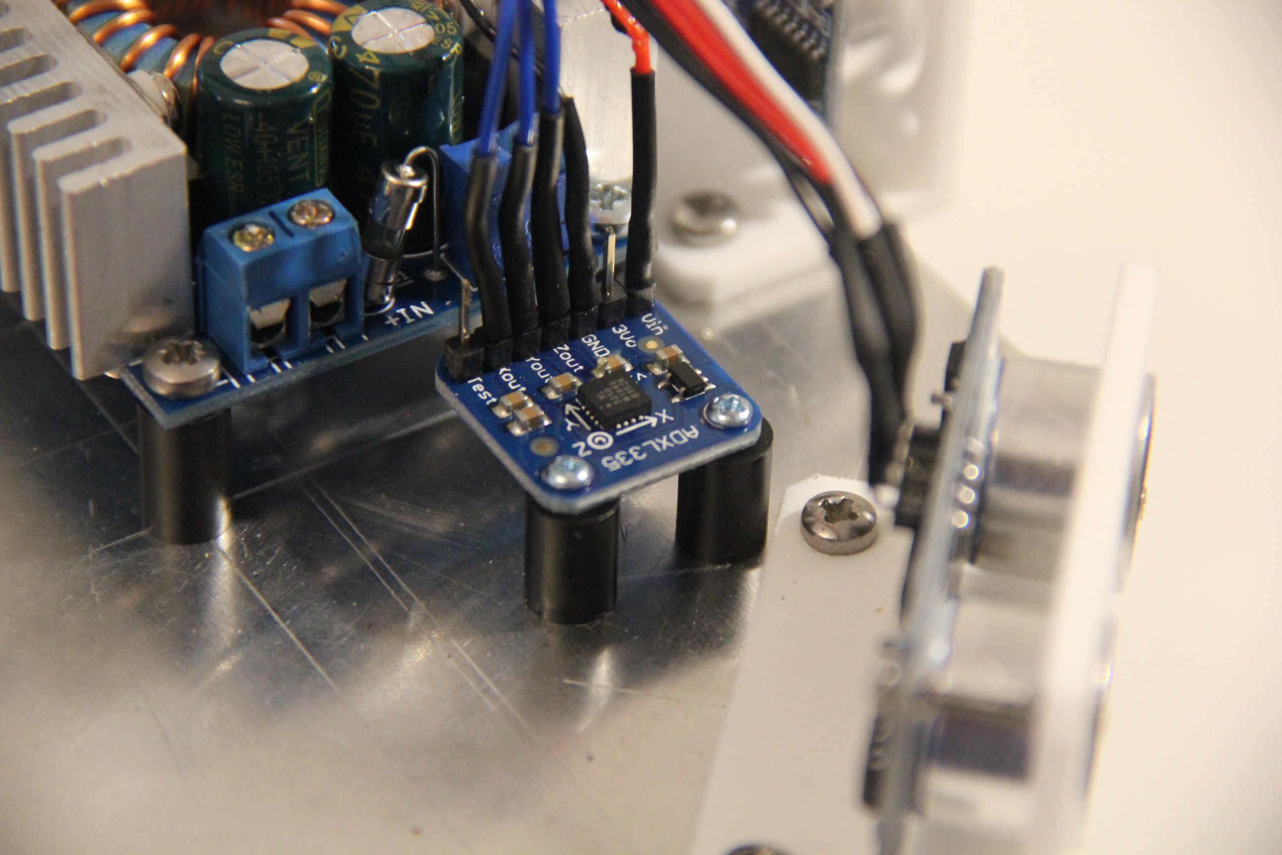
Sensors: 7 x HC-SR04, 2 x microphone, 1 x Raspberry Pi camera, 1 x RGB and Gesture Sensor - APDS-9960, 1 x PIR, 1 x flame sensor, 1 x humidity, barometric pressure and ambient temperature sensor, 1 x FIGARO TGS 2620 gas sensor, 1 x voltage sensor, 1 x 3-axis accelerometer
Power source: LiPo 11.1 V, 5500 mAh
Target environment: indoors
My design goals
- Make everything Open Source
- Use off-the-shelf components whenever possible
- Make it as easy to build as possible
- Cost less than USD 500 to build at home
- Make it modular and easy to upgrade
- Make it easy to customize and open to improvements
- Build an actually useful robot companion, not just a toy
- Step-by-step building instructions will be provided completely as 3-D drawings (like LEGO or IKEA)
System design
I will probably use a behavior-based robotic system, first suggested by Rodney Brooks (1986). Below figure shows an example of a behavior-based robot control architecture:
One can visualize a behavior-based architecture as a layered stack of parallel behaviors where the behaviors at the bottom deal with the survival of the robot and the behaviors at the top achieve desirable goals if opportunities exist. The design of a behavioral control system proceeds incrementally. The first layer is designed, tested on the robot and refined until it is satisfactory. At this point, the robot is already operational. Then, the second layer is designed, tested and refined. At this point the robot can make use of both types of competences. And so forth... [quote from Bio-Inspired Artificial Intelligence - Theories, Methods, and Technologies, The MIT Press].
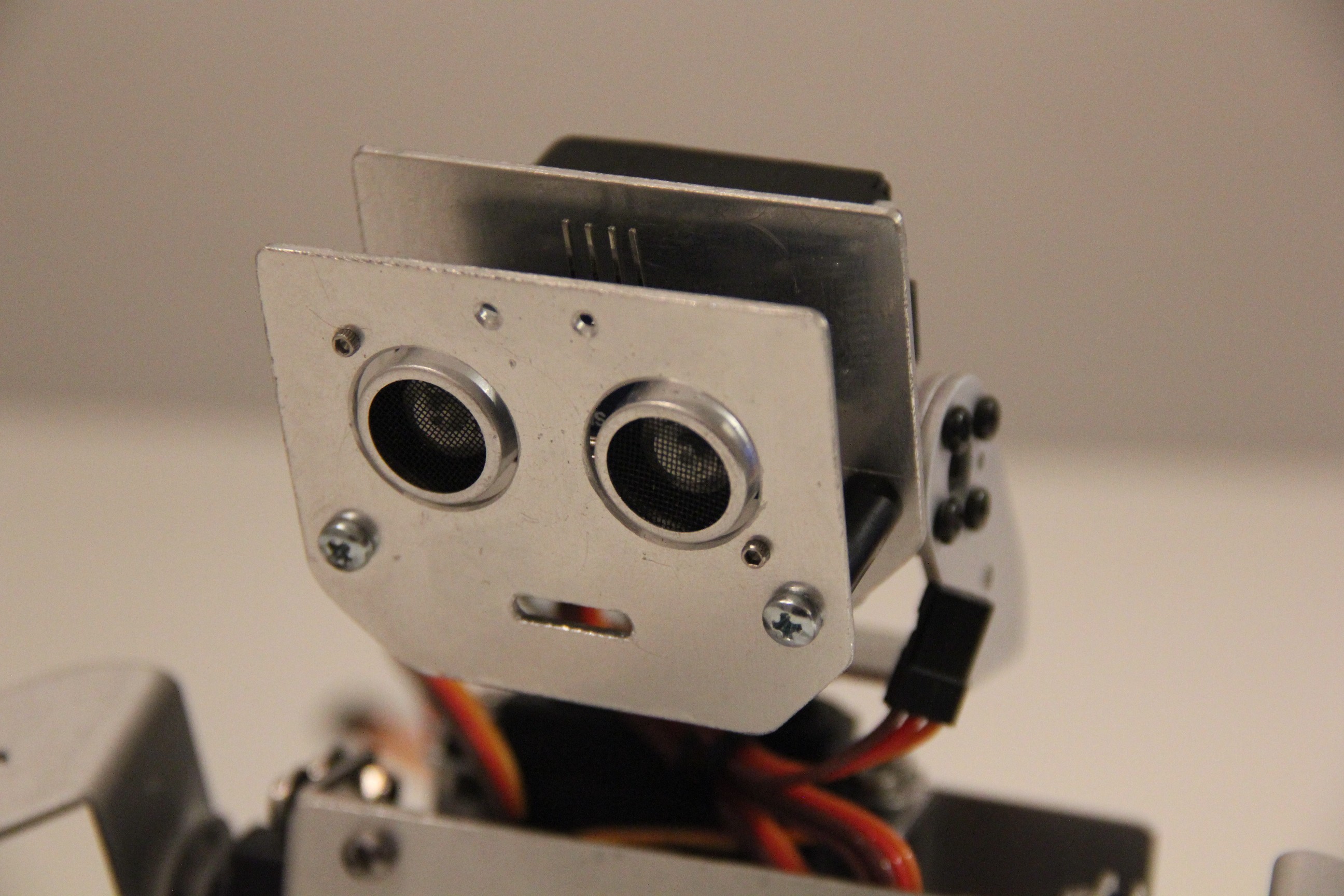
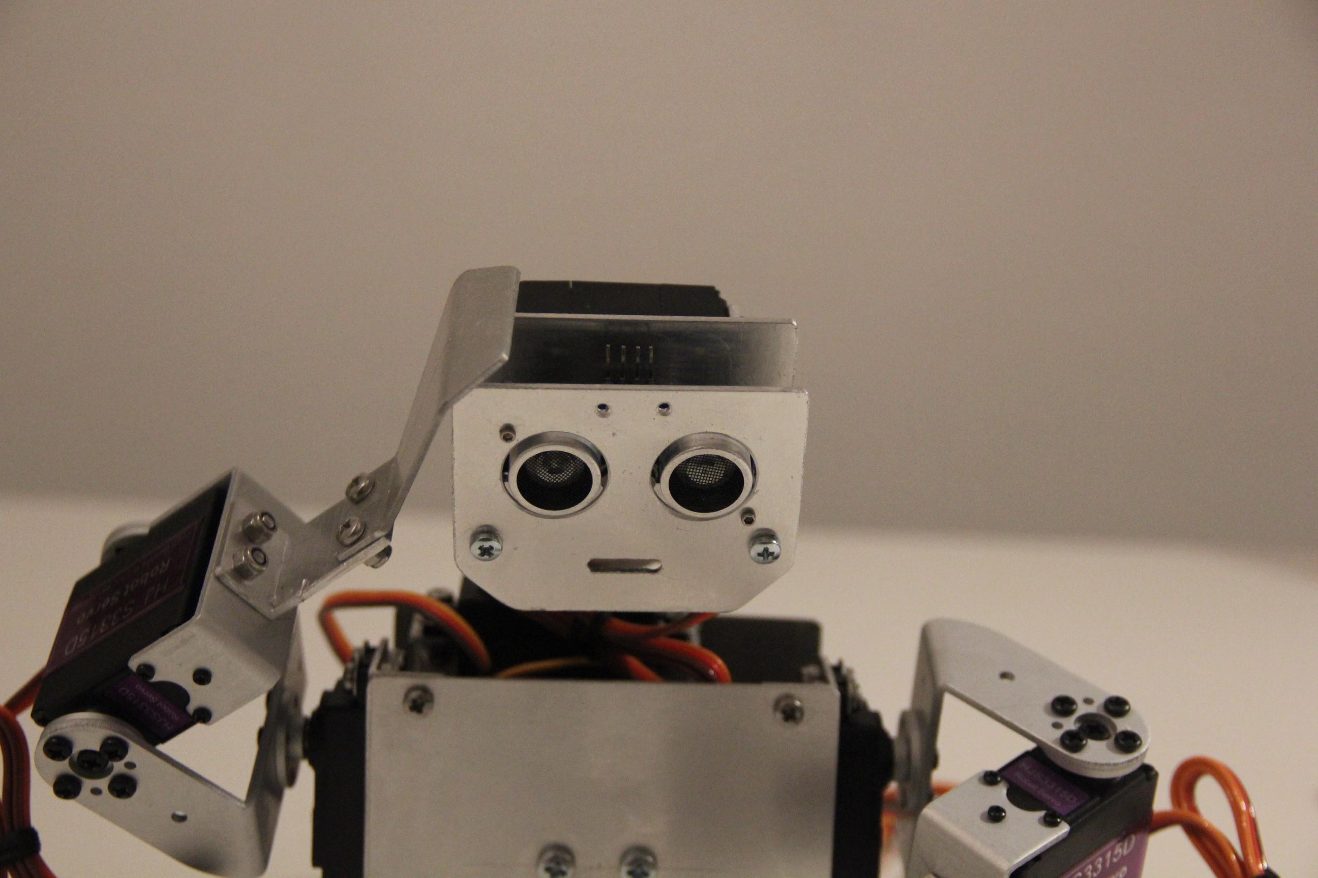
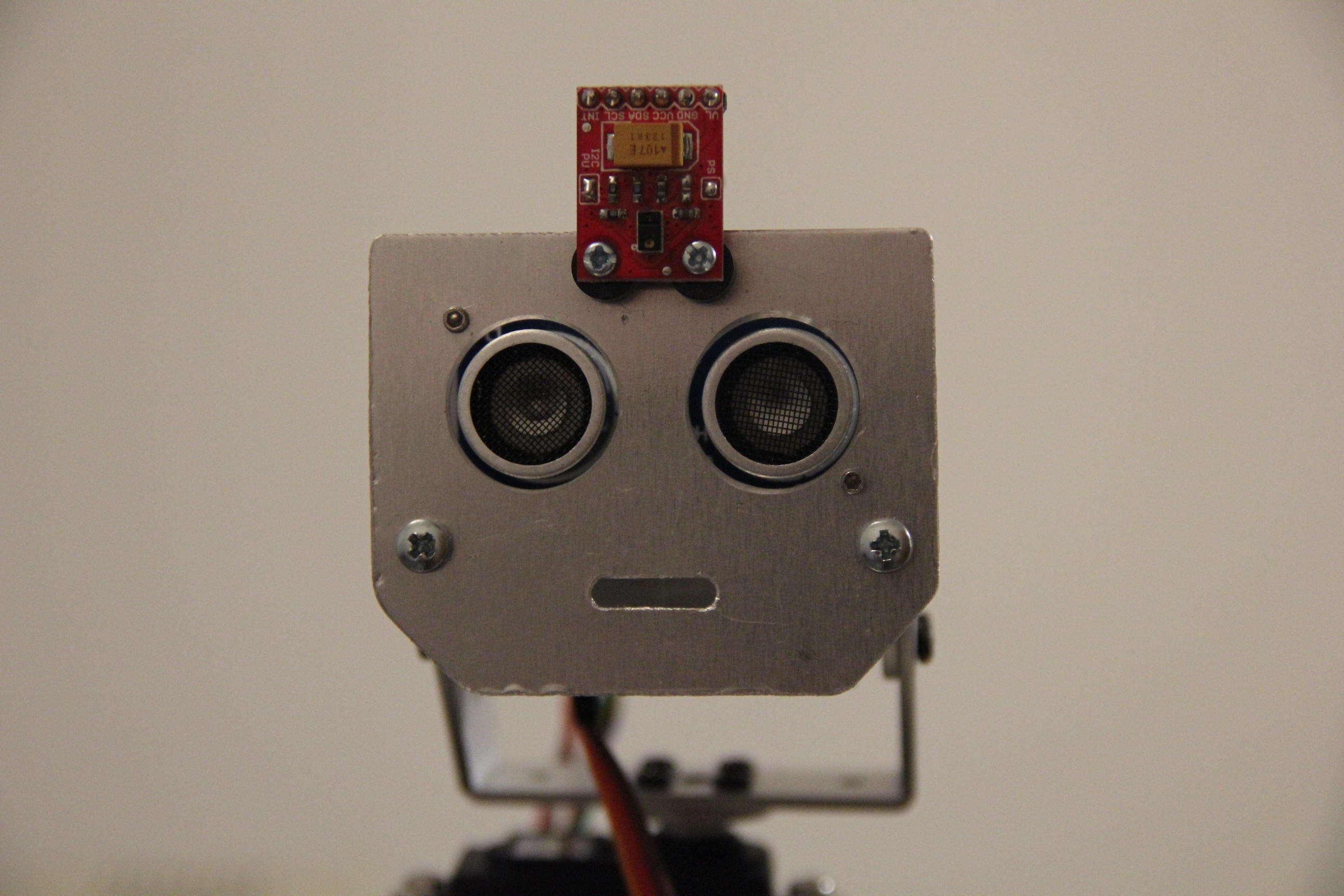
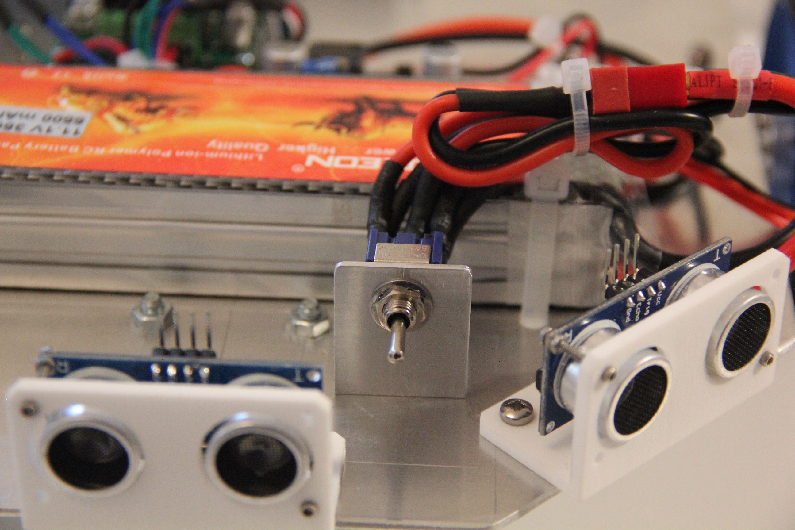
 Ultrasonic sensors


 Pengu MC
 Ben Peters
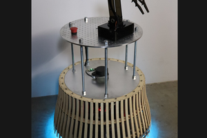
 Will Donaldson
 Lars
Lars
smart project for educators.
We are looking who would like to make an educational plan for DIY SelfieBot
endurancerobots.com/en/robots/diy-selfiebot/