0%
0%
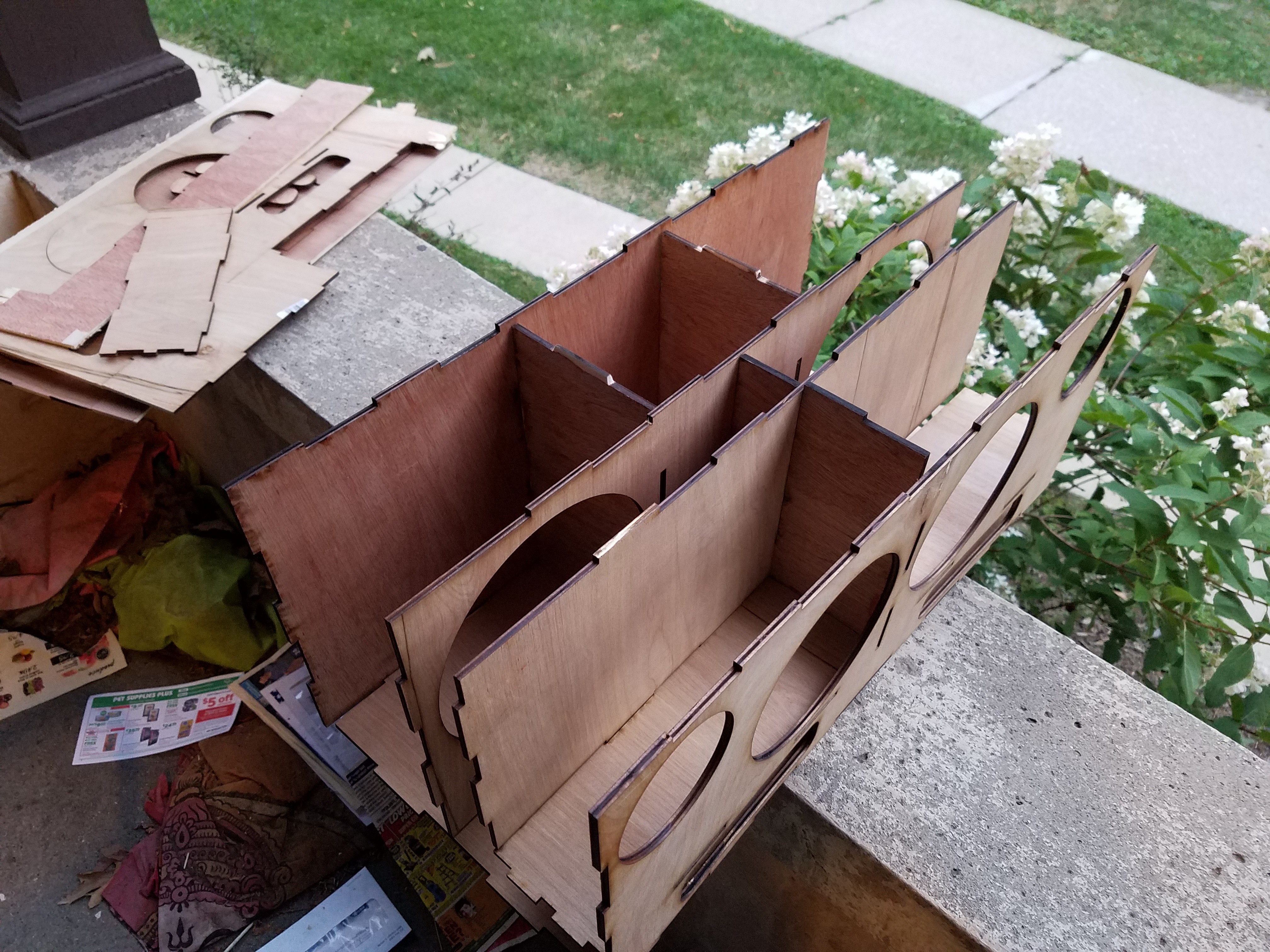
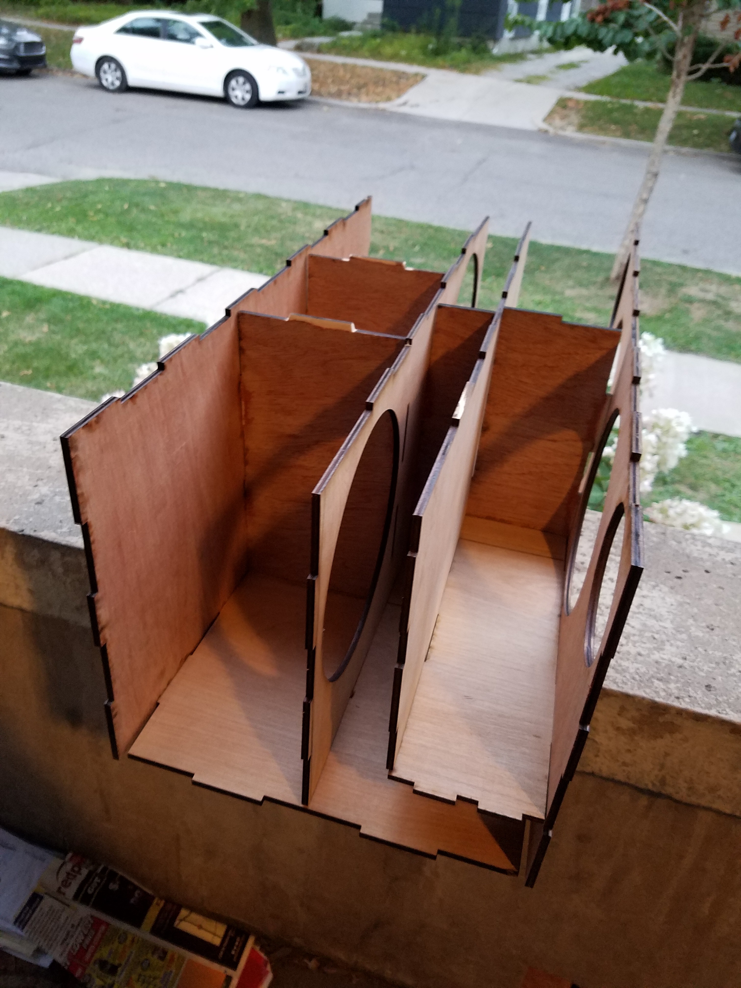
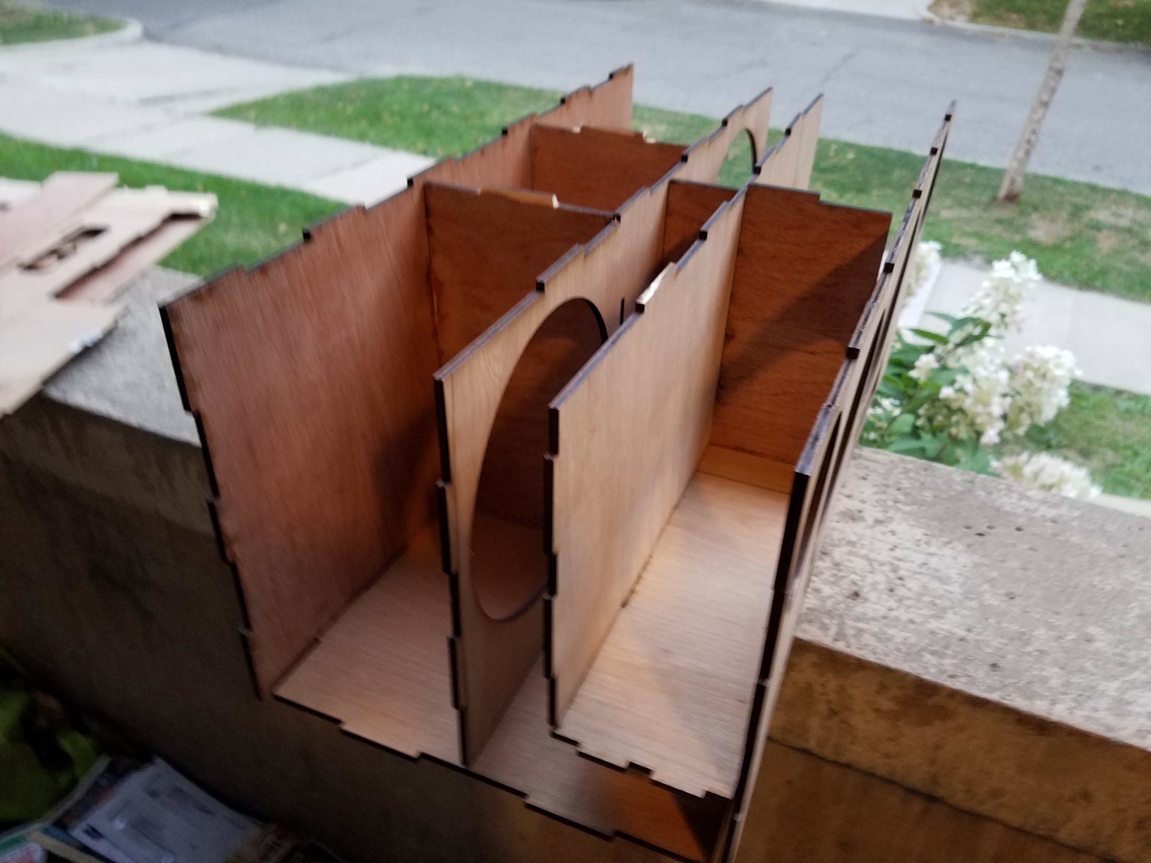
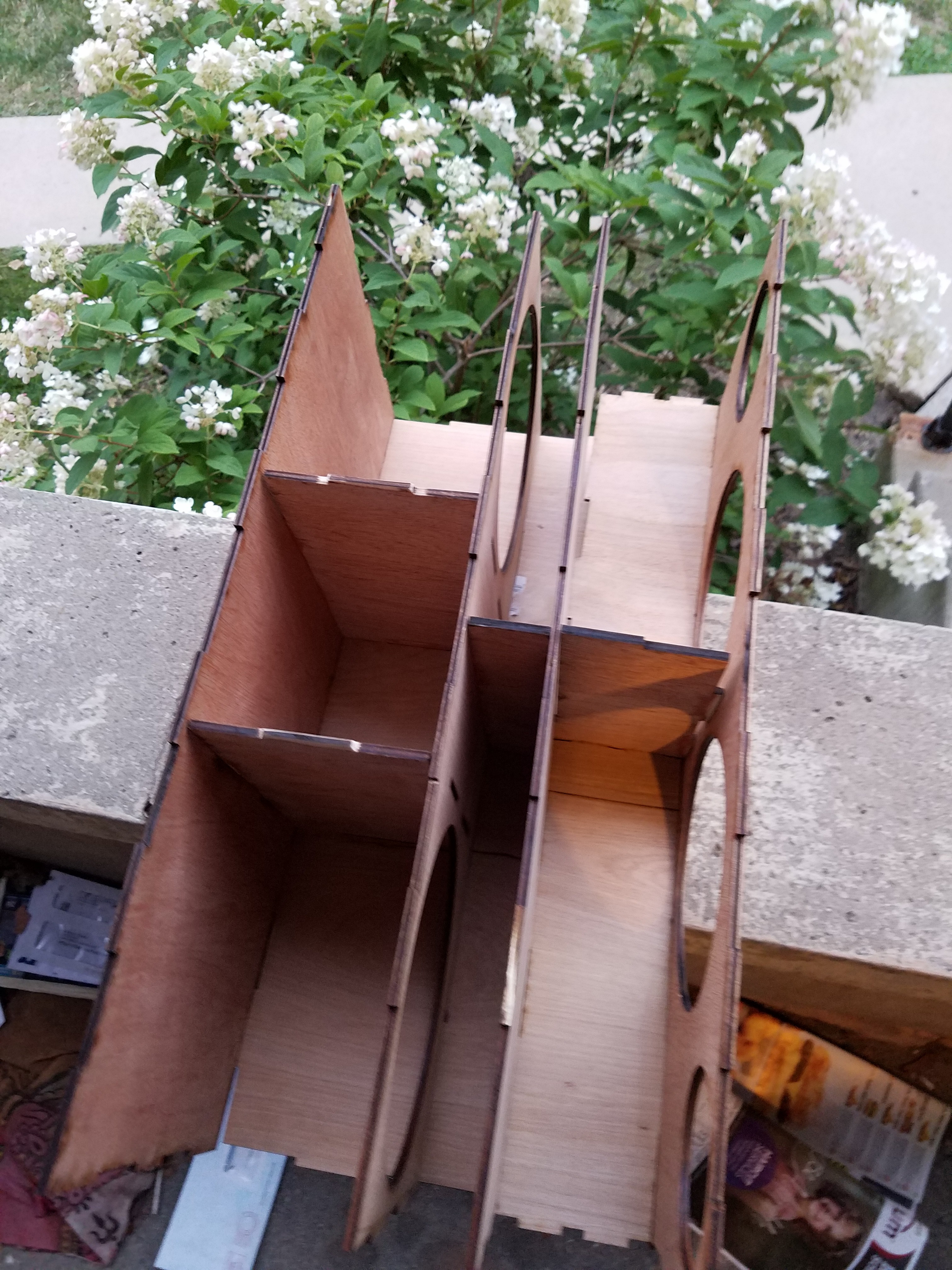
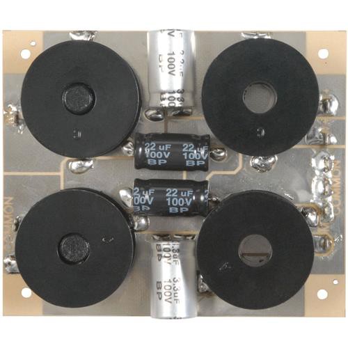
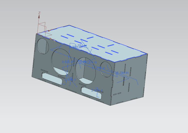
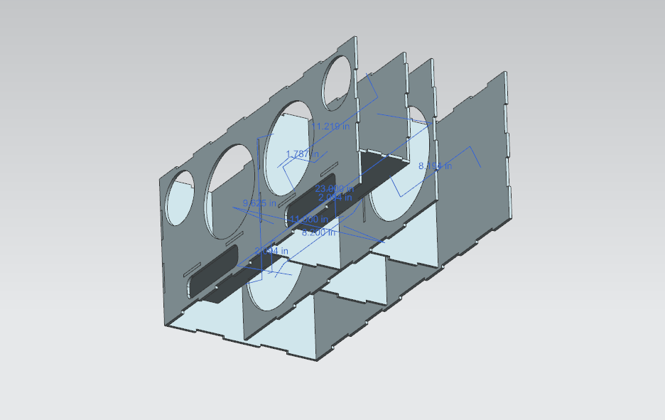
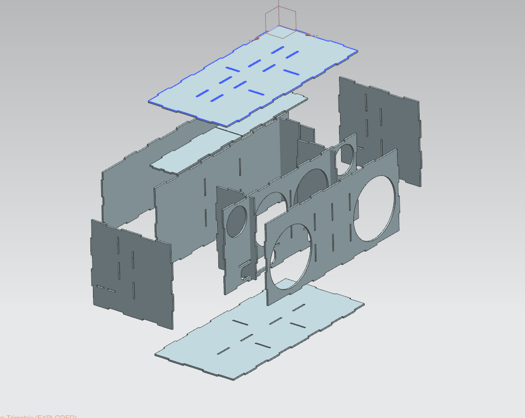
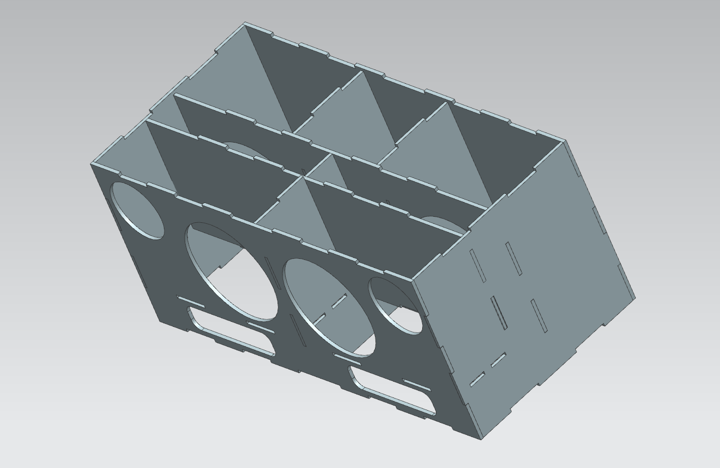
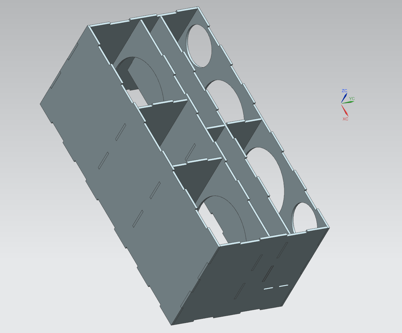
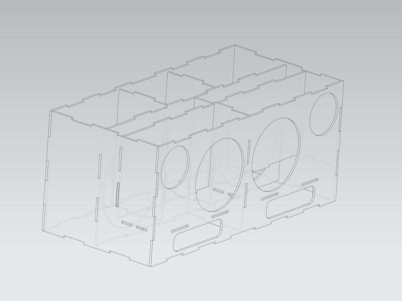
Laser cut speaker enclosure
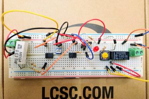
Laser cut speaker enclosure to house 6 speakers (3 left 3 right), 90W amp with 3-way crossovers on each side, and some Arduino shennanigans.
Become a Hackaday.io member
Already have an account? Log in.
Just one more thing
To make the experience fit your profile, pick a username and tell us what interests you.
Pick an awesome username
hackaday.io/
Your profile's URL: hackaday.io/username. Max 25 alphanumeric characters.
Pick a few interests
Projects that share your interests
People that share your interests

 Lithium ION
 Caleb W.
 Ted Yapo