Close
0%
0%

The Summons

Like the "Help me, I've fallen and I can't get up!" Only without the monitoring service.

Similar projects worth following
518 views
The Summons is a device for people who live alone and are concerned about reaching help in case of an emergency or accident. At its core, the Summons is a small, waterproof, ruggedized cordless land-line phone that you wear on your wrist or on a lanyard. It is too small to have a keypad, and also avoids having to remember numbers in an emergency. Instead, the Summons has a small number of buttons to speed dial pre-programmed numbers, which can be a friend, relative, or 911. As an accident could leave the user incapable of speech, the Summons also plays a pre-recorded message before connecting the user to the person called.

There are other alert devices on the market, but they all connect to a monitoring center that charges monthly fees - and there are a few horror stories where a company shut down the center and continued collecting money. The Summons bypasses the monitoring center and connects directly to a trusted local person or an emergency number.

The challenge: Design a device for somebody who has health issues and lives at home to be able to summon help in case of an accident or medical emergency. There are several existing medical alert devices, but they all rely on paid monitoring services. These monitoring services are, at best, another bill to pay for someone who may be on a fixed income, and in worst cases, some monitoring services have failed to actually monitor their devices and left callers without any response.

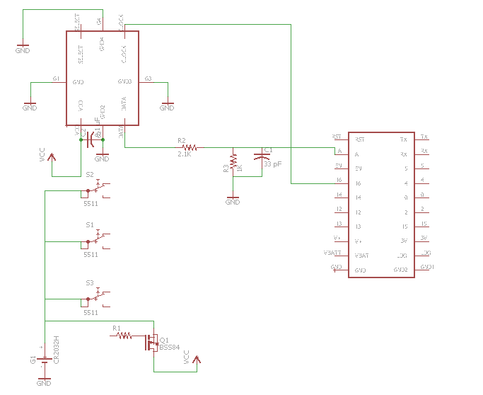
Therefor, this device does not rely on external monitoring services or require any ongoing fees beyond having a telephone line (POTS, VOIP, etc) and electrical power. It will directly contact people of the user's choice by phone, which can be a friend, relative, emergency service, etc. As the user may not be able to speak in an emergency, the device will play a prerecorded message when the call recipient first picks up, then allow the user to talk to the call recipient.

Other requirements:

1. The device must be easy to use by a person who is not particularly adept with technology.

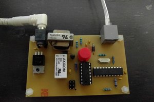
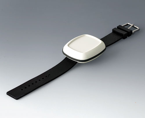
2. The transmitter must be small and compact, and able to withstand dropping, liquids, and in general, not be damaged in whatever accident requires calling for help.

3. The transmitter needs sufficient range to reach anywhere in a large house and sufficient battery power to operate for several days when not used and for around 20 minutes when placing a call.

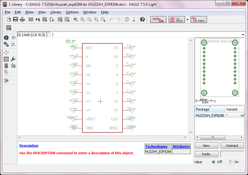
Licensing: All content original to this project is released under a GPL v3.0 open source license. It will need several prepackaged, closed source modules in order to comply with FCC requirements for telephone and wireless connections with the resources available to develop this unit.


  • 2 × HUZZAH ESP8266 Breakout Wi-Fi and microcontroller module
  • 1 × OKW Body-Case IP67 rated mini enclosure
  • 1 × Hitachi compatible LCD Alphanumeric display
  • 1 × Cermetek CH1840 Data access arrangement (telpehone) module
  • 1 × Custom transmitter PCB Small circuit board for transmitter side.

View all 7 components

  • Starting work on the schematic

    dodgedart27004/16/2016 at 18:20 0 comments

    Getting started on the schematic. I'm using a microphone on a chip with a PDM output, fed through a low pass filter into the ESP's analog input with the ESP providing the clock signal. You'll also see a start on the circuit that provides the power supply, which can come in through either a hold signal supplied by the ESP or through the three input buttons. This way, the device will turn on when any button is pressed and will remain on as long as the ESP holds the signal low.

    Too bad the microphone on a chip devices are only available in surface mount, and with weird pad arrangements at that. Some need circular pads or beveled pads - no SOICs or other convenient things that would be in EAGLE's library. A through hole one would make prototyping a bit easier. Well, that's what they make hot plates for, isn't it?

  • Getting started on the transmitter board

    dodgedart27004/09/2016 at 15:35 0 comments

    So, it's time to start the real design work. I use WinQCAD at work for PCB design, but it's no longer available, so I have decided to draw this one up in EAGLE. First order of business is to create a CAD file for the Huzzah ESP8266 breakout module footprint. Sure, there's probably a few out there, but making my own is a good exercise in learning the new software. I generally prefer to have my CAD symbols put the pins about where the real device has its pins, so I can better visualize how the routing will work while I draw the schematic. So my module symbol puts the pins in the same order as on the actual device.

    In addition, I've created an MIT-licensed GitHub page to store CAD files that I might use across several projects and might be useful for others, so they are free to use by anyone (even commercial products) without worrying about GPL restrictions. The Huzzah footprint is the first file I've uploaded there.

  • Huzzah! It's more powerful than I thought.

    dodgedart27004/07/2016 at 00:50 0 comments

    When I had originally chosen the Huzzah ESP8266 breakout board, I hadn't used one before, and had envisioned using it as a serial-to-wireless transceiver to take the serial data from a separate microcontroller and pass data back and forth between the transmitter and the base station. But after having a look at its spec sheet, it's clear this little board has a lot more to offer. It's clear that I need to rethink my choice of components.

    In addition to the wireless connectivity, it has nine GPIO pins and an analog input. That's easily enough for a Hitachi LCD on the base station or some push buttons on the transmitter, audio input, and a PWM output I can use as a DAC to generate audio output. So - it looks like I might not need that Teensy after all!

    For the transmitter, I'd basically just need to create what is in effect an audio shield for the Huzzah, and some circuitry to turn power off and on. (It has no reason to be on all the time, so it will only power up when you activate it and turn off when the call hangs up.) For the base station, nine GPIOs probably won't be enough - it will make sense to have a separate microcontroller to handle some of the functions, communicating with the Huzzah over serial.

    A Huzzah audio shield may be a worthwhile spin-off project, in and of itself. This wouldn't need the same power-on and power-off functions, as it would be more of a general purpose device.

  • Finding the right enclosure

    dodgedart27004/02/2016 at 17:57 0 comments

    This project would be a lot more difficult for others to replicate if they have to fabricate their own enclosure. Sure, making a wooden box for the base station wouldn't be too difficult. But the transmitter needs a sealed - preferably IP67 or better - case. And lugging around some big NEMA box won't fit the bill, either. So I needed to track down a suitable off the shelf case, small enough to easily tote about, and preferably with a form factor that made it easy to wear. And it would be best if they were something the average hacker can order just one of, instead of something with a MOQ of a couple hundred.

    Hammond is a pretty common go-to company for project boxes, but their smallest sealed plastic box was about 4" x 3". Workable, but not ideal, and putting it on a lanyard would require drilling a hole for mounting hardware. I'll keep them in mind in case the final circuit board turns out to be too large. And their plastic cases have some good candidates for the base station.

    After searching several other suppliers, it turns out OKW already offers a lot of cases intended for medical equipment, and they happen to have a case designed especially for tiny wearable devices: the Body Case. They even offer lanyards and wrist bands. At $14 each, the case is a bit more expensive than an Altoids tin, but is perfect for this application.


  • Prototype component selection

    dodgedart27003/19/2016 at 15:58 0 comments

    There are off the shelf dev boards for many of the specific functions the device will carry out. Once the dev board based prototype works, I can lay out a dedicated PCB to allow for a smaller form factor.


    The first key component choice is how to hook the base station up to a telephone line. After doing a bit of research, it was quite clear you can't legally just make a home-brew circuit and wire it straight to your telephone line. In the US, the FCC requires a registration for any device plugged into a telephone line. And with good reason – something feeding the wrong voltage into the wires can cause serious damage to the switching equipment at the other end.


    This doesn't put home-brew telephone equipment out of reach, though. Cermetek sells a number of modules that are pre-registered with the FCC, and the FCC considers their module to be the device plugged into the phone line. This lets you build whatever electronics upstream you need, without having to jump through hoops to get it tested and registered. They're not particularly cheap, but it beats paying a fine. So this project will use a Cermetek CH1840 telephone line interface module.


    Next is the choice of microcontroller board. For simplicity, I will be using the same board in the base and the handset. Since I don't have very much experience with embedded microcontroller code, good support and existing audio libraries are highly desirable. Although the Raspberry Pi 3 has both built in audio and WiFi capability, the hardware design is not open enough to allow taking the design from a dev board to a dedicated PCB, so that rules it out. While the Arduino family is one of the best documented and supported platforms, it does not offer much for audio capabilites. So the most reasonable choice for microcontroller board looks like it will be a Teensy 3.2.

    After that, the Teensy has its own dedicated audio adapter. To connect the two Teensys wirelessly, the prototype will use HUZZAH ESP8266 modules. I'll see if that provides adequate range.

View all 5 project logs

Enjoy this project?

Share

Discussions

Similar Projects

Does this project spark your interest?

Become a member to follow this project and never miss any updates