 Amar Potdar
My little lab needed little power supply. For testing and simple powering purpose. Main goal here is
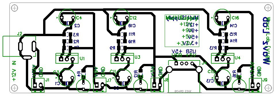
- Should be extremely low cost.
- Should be Single layer, for DIY PCB Etchers.
- Should use components, which are easily available.
- Should be,
- Easy-to-Assemble
- Easy-to-Test
- Easy-To-Troubleshoot.
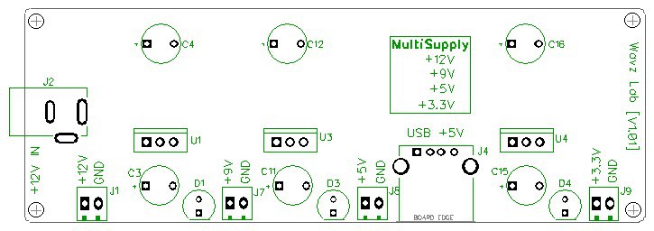
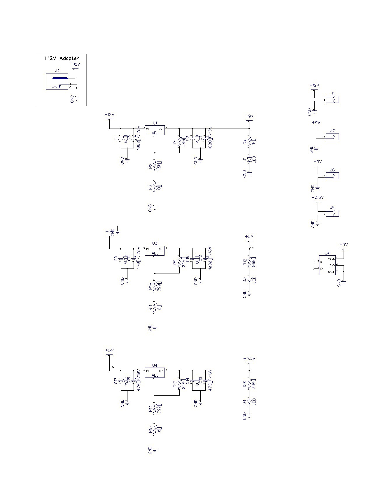
Circuit designed around:
- LM317 Adjustable regulator. With Heat-sinks.
- DC Socket at Input.
- Low cost SMD 1206 Rs & Cs.
- LED for POWER Indication.
- Terminal Blocks for each Output.
- Bonus USB-A-Female Connector [+5V],
Design Files are licensed under the CERN OHL v. 1.2.
You may redistribute and modify this documentation under the terms of the
CERN OHL v.1.2. (http://ohwr.org/cernohl). This documentation is distributed
WITHOUT ANY EXPRESS OR IMPLIED WARRANTY, INCLUDING OF
MERCHANTABILITY, SATISFACTORY QUALITY AND FITNESS FOR A
PARTICULA.
 Tony
Tony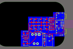
 AVR
AVR
 Arshmah Shahkar
 miguelmurca