 Quinn
QuinnIn the prior post I discussed the plumbing. At the bottom of the first picture were two boxes. The black one at the base of the accumulator contains connections and relays to remote control the system. I knew I needed remote control, and there are a lot of ways of implementing such. Wireless is an option, though it complicates things, makes it less reliable, and has some added risk for incorrect behavior. Given the safety issues, it is unmost important to not have accidental firings. For this reason, wired connections are used. Further, when using log wires, they can serve as antenna, and random spikes can occur. To prevent this from causing problems, activation of elements requires a steady non-trivial current. For robustness, I opted to just use relays in this box for switching the hot surface ignitors, as well as the solenoids. I was initially concerned about time delay's introduced by using relay's on the solenoids, but I quick tested the ones I was looking at using on a scope, and with a 4ms switching time, really shouldn't have any realistic effect. There is already going to be a delay in the solenoid anyway.(I couldn't find the spec for this model, but it looks like 50-200ms are reasonable values for this size) The relays require about 100mA to activate, coupled with the inductive nature and slow operating time should prevent any electrical noise from accidental triggering.
Normally I wire my circuits on through plated perf board, with point to point wiring. With this circuit, I decided it was a good opportunity to hand route a PCB as there are few traces, some are higher current, and the larger terminals are not on 0.1" spacing anyway. I did this with a blank double sided copper clad board, and a rotary tool(ie, dremel) to isolate traces, and peeled off larger sections of copper as needed, and component pin holes drilled on a drill press. The result, though very rough and crude turned out great, and was quicker to do than it would have been to draw the schematics and layout.

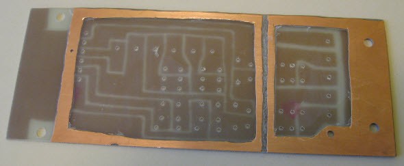
As I only had double sided clad, I simply created ground rings on the topside. This way if there is a short with the AC side, it will hopefully short to the ground and blow the breaker instead of shorting into the low voltage side. Note the isolation moat between AC and low voltage sides. AC side is grounded to earth through the AC cord. Low voltage is not grounded.
The circuit is easier to follow soldered up:
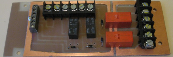
Relays are simple 12VDC. The black ones rated for 3A @ 30VDC, and the orange ones for 15A @ 120VAC. Flyback diodes were installed to keep noise down, protect the controller, and make for quicker opening of the relays. The footprint was made to support the larger relays in the place of the smaller ones in case I ever wanted to change them.
Terminals on the right are for AC ground, neutral, and relay contacts. These serve to switch the AC outlets that the hot surface ignitors are plugged into.
Terminals in the middle are for 12V power for the system, and relay contacts. These relays are for switching the 12V solenoids.
Terminals on the left are for wiring to the remote.
Bottom side, nothing exciting here.
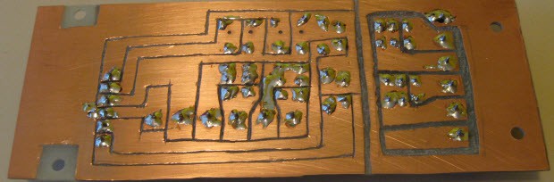
That board is pretty much all that is in the black box.
The grey box at lower left of the image is a project box I had sitting around which already had 5 switches mounted in it. I simply replaced two with buttons, and wired it to be a quick and dirty manual control system for testing while I finish the final controller. One switch serves as an enable for all the others, two control the AC relays, and the two buttons control the solenoids.
The last bit of electronics are in the wire leading from the black box up to the solenoids. I installed flyback diodes for these in the middle of the wire. I wanted to keep them closer to the solenoids, but didn't have a robust way to mount them closer. So I soldered them in the middle of the line, protected with heatshrink, put a couple steel wires in parallel(to avoid bending which can break solder joints), and another layer of heat shrink. These are very large solenoid coils, drawing just over 1A at 12V, and again, I wanted them to de-energize quickly.
Discussions
Become a Hackaday.io Member
Create an account to leave a comment. Already have an account? Log In.