 Quinn
QuinnThe added circuitry is reasonably simple, mostly just a bunch of IO with lots of protection. Features were put in place to protect against damage due to electrical spikes or static discharge. This is especially important given that in this application, I expect to have 50ft of wiring connected to some of the IOs, and wanted to be able to support larger lengths.
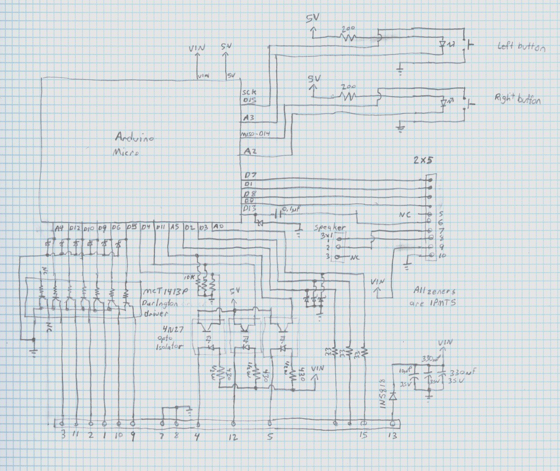
Six of the arduino lines run past 5V zener transient voltage surpressors. I am using 1PMT5 devices because I had a bunch scavenged from another board, and they are really good devices, if not the most convenient package. Past these, they run to the base inputs of a darlington open collector driver chip, an MC1413, again used because I had a couple on hand scavenged from something else. The collector pins run to the DB-15(bottom in schematic). These will serve as the primary outputs for driving relays, etc. The open collector choice was intentional as it means the different outputs can be pulled to different voltages depending on the need.(ie, could use 5V, 12V relays or other loads) 4 of these are on PWM pins in case that feature is ever desired.
Three of the arduino lines are connected to 4N27 opto isolators to serve as the primary inputs. Given the high isolation already afforded by these, I didn't bother with the TVS's. The other side of the opto's have the led anode connected via resistor to the power input, and the cathode to the DB15. This allows the external input to simply switch this pin to ground to activate the input. The resistor is a 430ohm, 1/2W, chosen to allow functioning within specs of the opto, for the entire 8-20V power input range.(at 8V, this is 13mA minimum, and at 20V is 32mA.
The UART pins of the 32u4 are wired to the philips uart to communicate with the keypad and lcd.
Two pins were wired to the RS232 level converter. Pins chosen to have the pin change interrupt capability on the RX. This will allow a software UART to run on the arduino out the connector on the bottom of the controller if ever desired.
The I2C lines(D2/3) were wired past 5V TVS's, through 33ohm resistors and to the DB15 as a possible expansion for the future. The resistors will have negligible affect on the slow edge rate I2C, and better allow for any possible surge dissipation. No pullup was added to allow 3.3 or 5V operation supplied by the slave device(s).
One PWM output is wired past a 5V TVS, and through a 0.1uF ceramic capacitor. This feeds into the hand paddle board. The paddle already had an output of the philips microcontroller feeding through a capacitor into a FET which drives the speaker. The output of my capacitor will also be tied into the FET gate, which will allow either microcontroller to drive it. The purpose of the zener is to take positive and negative spikes which will result from this arrangement. It is a bit redundant because the 32u4 already has protection diodes on it's ports, but better safe than sorry.
Two pins connect to the installed arm/firing buttons, and two more wire to the LEDs built into those buttons.
One of the analog inputs is wired past a 5V TVS, through a 33ohm resistor, and to the DB15, again as a possible future expansion.
I took care to not create conflicts with the SPI port, leaving MOSI and SS unconnected and MISO and SCK only connected to the pushbuttons. As the pushbuttons are NO, as long as the buttons are released, the SPI port can still be used for programming the 32u4.
DB15 pinout was chosen to provide 2 grounds, with the analog signal between. It and the I2C channels are also separated from the darlington outputs and opto inputs by the power line, also for a bit of shielding.
A 2x5 header(center right in schematics) was mounted to create a removable connection to the original circuit board in the controller. A 1x3 header was placed to relocate the speaker connector as the original location on the original board took up too much height and prevented my board from fitting.
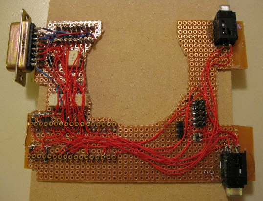
I used mostly surface mount parts because I find them so much easier to fit into projects, and they really are not much harder to use. Especially resistors, with the common 0402-0805 sizes easily bridging between two 0.1" spaced pads, taking up practically no additional space, unlike leaded resistors. This was also very useful here as the back of the circuit board needed to remain completely flat to fit into the case, which only had a thin space for me to work in. Everything is topside placed and wired.
A ribbon cable segment was wired into the appropriate points on the backside of the original controller, with a 2x5 conector to mate with the new board. Here are both boards, mounted in both halves of the case, ready to be closed up.
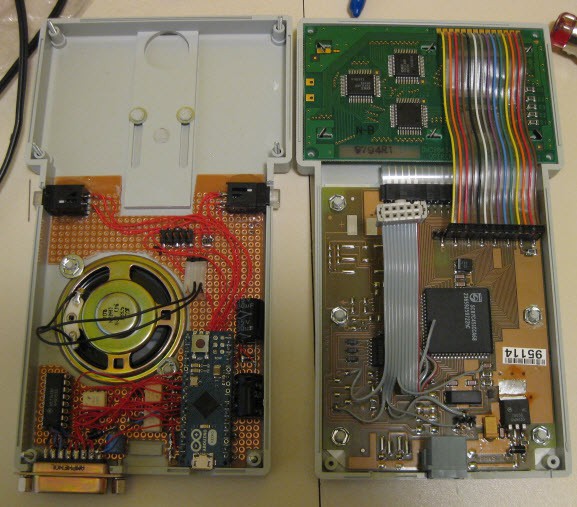
I also added a local decoupling cap on the original controller board at the input, at the input of the DB15 connector(after protection diode), as well as a pair of large capacitors on the right which serve as a quick hold up in case of momentary power loss.
Discussions
Become a Hackaday.io Member
Create an account to leave a comment. Already have an account? Log In.