Close
0%
0%

Luke - Open Framework Multimeter/Logger

DMM dedicated to PC/smartphone with cross platform SDK provides user-friendly measurement and automation system

maxMax
Similar projects worth following
Luke is a DMM, Digital Multi Meter, used with PC/smartphone for measuring DC voltage or current. However, this project is not just making an instrument but also focuses on establishing user-friendly measurement and automation system with open source SDK.

For example, logger software working on PC can directly get measurement values from Luke via USB and draw real-time waveform. You don’t need to read numbers shown on DMM and type a keyboard again and again to take statistics on PC. In addition, if you make some codes calling API provided by SDK to control Luke, your program can automatically measure data and use it.

As you know, there are a lot of similar products like Luke and expert engineers could do the same things by using specific IF such as GPIB. However, it is far from this project's goal because it is complicated and depends on proprietary software.

Measurement is fundamental to make or hack something. Let's work together to make it as open source!!

Introduction

The aim of this project is to offer user-friendly measurement and automation system. As you know, VISA, which stands for Virtual Instrument Software Architecture, is a industry standard library for this purpose. It provides the programming interface between application software and measurement instruments using GPIB, USB, LAN and/or UART. Although this solution is very practical and widely used in production line, it doesn't meet the basic requirements for DIY projects. This is because it is relatively large-scale system, and specifications are totally controlled by measuring instruments manufacturers. First of all, it usually depends on proprietary software released by vendors. This makes it difficult for you to build automation system with user program or a new gadget created by yourself.

https://cdn.hackaday.io/images/3873681460983902652.png

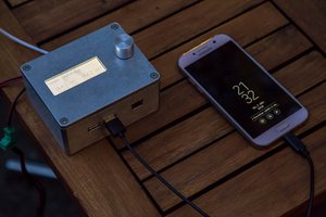
Therefore, I decided to make both of a simple multimeter/logger named as Luke and open source SDK which supports multi-platform. Luke doesn't even have display nor any control button. It should be connected to PC or smartphone via USB, and then application software or command line tool controls it and acquire data. I'm trying to make it simple as much as possible to improve usability and flexibility. For example, you don't have to install device driver because Luke is recognized as HID. Also, APIs for C++/Python will be prepared for users. It will be available to make your own measurement system based on this project. Please see below for the details.

Luke specifications

Hardware
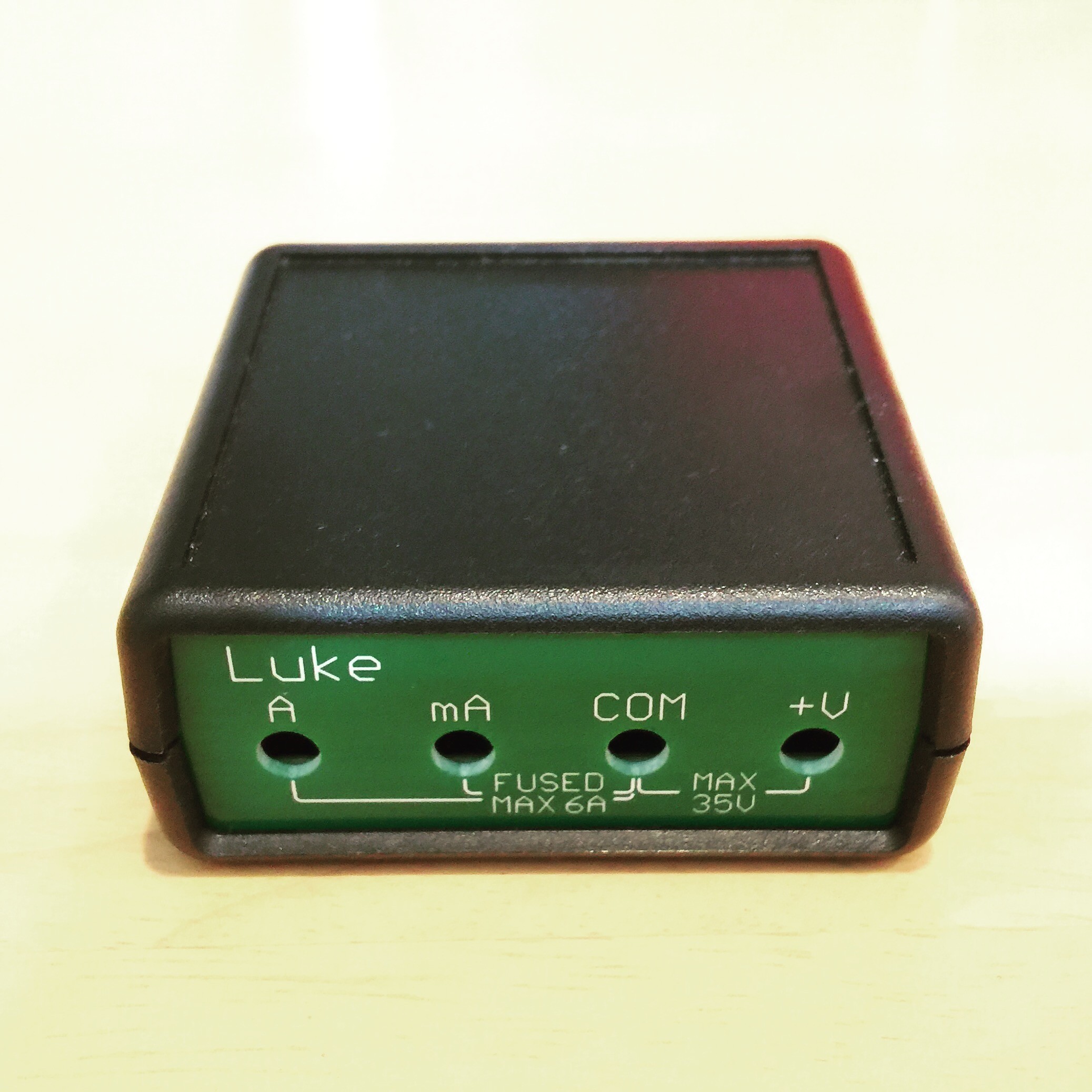
Measurement

  • 13bit ADC
  • DC voltage
    • High Range: -60V to 60, Resolution: 14.81mV
    • Low Range: -6V to 6V, Resolution: 1.498mV
  • DC current
    • High Range: -3A to 3A, Resolution: 0.80mA
    • Low Range -160mA to 160mA, Resolution: 40.0uA
  • Max sampling rate: 1kHz (T.B.D.)
  • Auto-range mode

Host Interface

  • USB Full Speed
  • Host interface is isolated from measurement circuits

License

Firmware

  • Dual-licensed under the LGPL version 3 and the Apache License version 2.0

Cross Platform SDK

Features

  • OS Linux/Mac/Windows/Android
  • Compiler: GCC, MinGW and MS Visual C++
  • Command line tool chain
  • API for C++/Python/Ruby
  • Sample program

License

  • GPL v2


Implementation


Communication protocol

How to talk PC software and device firmware is always big issue. It is not too much to say that design of this part determines whether a product connected to PC is valuable or not. For my products, I designed new protocol named TBI, ToolBit Interface, to exchange data by simple messages. This protocol has something in common with GATT for BLE (Bluetooth Low Energy). Firstly, a host computer and a device have different roles. A host works as client to send a command to server in order to read/write a value. On the other hand, a device works as server to response a command from client. In addition, a fundamental unit handling read/write data is called attribute. The data stored in attribute can have any type like int, char, float, etc, but the max length of data is limited to 32-byte. Each attribute is indexed by a unique 2-byte number, attribute ID. For example, a product name stored in firmware is defined as follows as:

Attribute
ID: 0x0000
value: "Luke"

This means you can get a product name by reading attribute ID:0x0000. The minimum set of commands to read/write attribute is defined for now as follows as:


OP_ATTR_VALUE_GET

Client Command Packet Format 
| Header | OP Code | Attribute ID |
| 1-byte | 1-byte  | 2-byte       |

Server Response Packet Format
| Header | OP Code |Return Code| Attribute Value     |
| 1-byte | 1-byte  | 1-byte    | n-byte(conditional) |


OP_ATTR_VALUE_SET

Client Command Packet Format 
| Header | OP Code | Attribute ID | Attribute Value     |
| 1-byte | 1-byte  | 2-byte       | n-byte(conditional) |

Server Response Packet Format
| Header | OP Code |Return Code|
| 1-byte | 1-byte | 1-byte...
Read more »

LukePlus_Rev0_3.pdf

INA3221 Solution Add FET to support auto-range mode

Adobe Portable Document Format - 48.14 kB - 05/23/2016 at 13:52

Preview

LukePlus_Rev0_2.pdf

INA3221 Solution

Adobe Portable Document Format - 47.38 kB - 05/14/2016 at 11:08

Preview

Luke_Rev0_2.pdf

Luke Rev 0.2 Schematics

Adobe Portable Document Format - 39.44 kB - 04/09/2016 at 04:17

Preview

  • 1 × PIC16F1454 Microprocessors, Microcontrollers, DSPs / ARM, RISC-Based Microcontrollers
  • 1 × INA3221 Power Management ICs / Power Supply Support
  • 1 × ADM3260

  • Auto-range function

    Max01/28/2017 at 15:29 0 comments

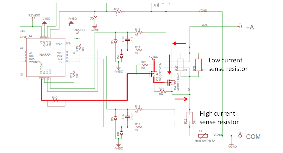
    Auto-range is feature to select suitable measurement range automatically. This function helps you when target signals have wide dynamic range. Especially, it works for software engineers who aren't good at measurement. For example, they sometimes fail to measure current because system reset happens due to voltage drop caused by impedance selected measurement range has.

    The important thing to avoid this issue is to change current measurement range to suitable one automatically and quickly. Luke has a tricky solution using a critical alert pin of the current monitor IC, INA3221. When ADC result is higher than threshold set by a register, it asserts a critical alert pin, and then turns on FET that bypasses shunt resistors. As result, impedance becomes lower because there is only high current sense resistor on the path.

    However, if you are measuring negative current, that is ADC result is a negative value, this auto-range function doesn't work at all. This is a limitation of this hardware solution using a critical alert function of INA3221.

  • Migration from INA226 to INA3221

    Max05/23/2016 at 15:18 0 comments

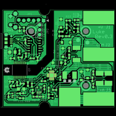
    I decided to change a power monitor IC from INA226 to INA3221, that is a 3ch current monitor, based on the discussions with a talented engineer on this page. Although ADC native resolution is downgraded from 16bit to 13bit, measurement range of voltage is expanded and auto-range select is supported for both voltage and current measurement. Auto-range function will be realized by alert pins of INA3221 which can notify system when the measured value exceeds the programmed threshold. These alert signals directly control FETs to select the optimum measuring range. Now I uploaded the latest schematics and modified the specifications of Luke. New artwork has been almost completed. I managed to put all components on the board which is the same size as 1st prototype.

    Artwork of LukePlus_Rev0_3


  • Submitted to The Hackaday Prize 2016

    Max04/24/2016 at 09:03 0 comments

    Thank you for being interested in my work and following this page. Now I'm pretty sure that the project is going in the right direction. I wrote introduction to clarify the project's purpose and then submitted it to The Hackaday Prize 2016!!

  • Create project

    Max04/06/2016 at 12:07 0 comments

    I started this project by myself couple of months ago.

    First prototype was built in February 2016 and then I studied how USB communication between PIC and host PC works by using HIDAPI, this is awesome library released by Signal 11 software.

    After the examination of hardware, I decided to change schematics to isolate signals and power between processor and measurement circuits. Now I'm making second prototype PCB.

    My short-term goal is to release hardware and software until this summer. Please keep in touch on hackaday!!

View all 4 project logs

Enjoy this project?

Share

Discussions

iansmusical wrote 03/24/2017 at 16:45 point

Hello,

I'm interested in the use in your project of the INA226 and INA3221. With adaptations could you tell me if it's suitable for use to measure the voltage and current on both the positive and negative rails of an audio amplifier? The rails will be +-42v and the expected current +-5A.

Thanks for your time,

Ian

  Are you sure? yes | no

Max wrote 10/07/2017 at 00:51 point

Hello @iansmusical,

Apologies for taking so long to reply but I have been away from this project and hackaday site since my first daughter was born half a year ago.

Sounds fun to measure voltage and current of audio amplifier. INA226 and INA3221 can measure low/high side current but common mode voltage should be from 0V to max 36V(INA226) or 26V(INA3221). Also, I think time resolution is not enough for sound data. It doesn't matter If you are interested in measuring power consumption of amplifier, though.

  Are you sure? yes | no

Max wrote 10/02/2016 at 12:54 point

Hello Consultant,

I'm sorry for the late update. I've been making software and firmware before verifying hardware. Now PC and micro-processor can talk to each other by using simple protocol which is inspired by GATT for BLE. I haven't written documents yet but source codes were uploaded to GitHub. 

  Are you sure? yes | no

Max wrote 09/03/2016 at 04:00 point

It might be required FPGA to archive 100Mhz sampling. I have seen some open source oscilloscope projects.

  Are you sure? yes | no

James Newton wrote 08/30/2016 at 18:09 point

I understand and respect your goals with this project. I wonder if there is any crossover with my DroidScript BusPirate project... it would be nice to have an analog front end for that. Also, the SDRAM thing needs a (high speed) analog to digital front end. I mention these only because you seem like the guy who might have the analog skills we need.

  Are you sure? yes | no

Max wrote 09/01/2016 at 06:28 point

Thank you for your comment. I know BusPirate. It is interesting tool although I don't have it. Actually, I want to make an oscilloscope in future but I should focus the current project for now.

What is your interesting frequency? If you want analog front end with high speed ADC like oscilloscope, SDRAM is required as you mention.

  Are you sure? yes | no

James Newton wrote 09/01/2016 at 15:28 point

over 100MHz.

  Are you sure? yes | no

Consultant wrote 07/12/2016 at 01:43 point

any progress in the last few months?

  Are you sure? yes | no

Max wrote 07/15/2016 at 08:32 point

Sorry for being late. I has been working on another prototype, that is my second project named Chopper HUB: https://hackaday.io/project/12349-chopper-hub

Now I’m soldering new prototype of Luke. I made two PCBs at same time to save shipping cost from China.

Thank you very much for giving me many useful advice. I understand your point. As you mentioned, there is room for improvement on this prototype regarding input impedance, a variety of ranges and dynamic range changing method. However, I’d like to move forward with current solution and focus software development for now. Of course, I have plan to implement some method to calibrate offset and gain.

  Are you sure? yes | no

Consultant wrote 07/15/2016 at 17:23 point

Good to see progress!

  Are you sure? yes | no

Consultant wrote 09/28/2016 at 00:08 point

You making any progress?  If you are I am not seeing it :-)

  Are you sure? yes | no

Max wrote 05/14/2016 at 13:20 point

Hi Consultant,

Thank you for your advice. I modified the schematic and uploaded it. The differences are adding voltage divider for voltage measurement, and changing shunt resistors to adjust resolution for my target. Also, I'm trying to use warning alert of INA3221 to change input range. This is very tricky but I'm pretty sure that warning output could be controlled like GPIO if registers were manipulated by micro-processor via I2C on purpose.

13bit ADC is not a big deal if some circuit for measuring range switching is implemented. I thought INA226 is good enough to measure voltage without switching circuit.

By the way, I do measuring power consumption of smartphones at a company. Therefore, 160mA range with 40uA resolution is used for standby current measurement, and 3A range with 0.8mA resolution is for other use cases. As for voltage range, 1mV resolution is required to measure battery voltage. That's my concern about measurement range/accuracy.

  Are you sure? yes | no

Consultant wrote 05/29/2016 at 21:52 point

progress!

You are getting the swing of this I see.  A few problems I do see.

You have to change your front panel. Bummer. But it will be worth it.😏

Warning and critical are common across all three channels.  Tricky is an understatement for using them for ranging control.  It will probably oscillate.  I would have just stuck a cheap I2C expander with 8 bit output and control the ranging that way.   Cheap and it will work 100%.

Typically when someone claims 1 meg or 10 meg input impedance on a multimeter the input impedance does not change depending on the range you select which could change the readings.  Yours will.  Consider this.  Reduce the 1 meg resistor so the total series resistance is always 1 meg or 10 meg.  (-27k?).  Then use 2 fets to connect the + input to either the high range or low range controlled by the expander.  You could easily add a bunch of ranges this way.  Thats how I would do it :-)

The current measurement can be done the same way for a variety of ranges as you require.  You might consider using one of the expander outputs to control shorting out that large 1 ohm resistor.  Using "Critical" sounds like trouble to me. That FET impedance is critical to your readings being stable.

I see you changed from .5 ohm to 1 ohm for shunt resistance.  That resistor is going to be tricky calibrating so be careful with implementation and power ratings.

Now that you have current on just one input consider removing that 1 ohm altogether using that circuit I referenced you to before (ucurrent).  Basically your multiplying the voltage by 100 on that 50 milliohm or another 10mohm to the resolution you want.  Gets rid of most of your burden voltage and no shorting out the resistor.  Both resistors could be there I guess or use same for both.  I have seen high end multimeters use similar circuits that tap various x10, x100, x1000 to get all the ranges and no shorting of high current resistors.

How are you planning on calibrating it?  Does it need calibrating more than once?

Are those resolution numbers in your schematic really step size?  

Can't you adjust the step size to something more standard by using different resistor selections?

As always, consider these inputs food for thought🙃 Its your design.

  Are you sure? yes | no

Consultant wrote 05/11/2016 at 20:34 point

Any progress?

  Are you sure? yes | no

Max wrote 05/12/2016 at 15:13 point

I uploaded the latest schematic that uses INA3221 and Op-amp for input bias. However, it is required to improve voltage measurement circuit because INA3221 has 13bit ADC and 1-LSB step size of bus voltage is 8mV. For example, adding another I2C ADC controller for voltage measurement or just using two or three INA226s instead of INA3221. Let's me think about it for a while.

  Are you sure? yes | no

Consultant wrote 05/12/2016 at 18:34 point

Looks better.  

Your voltage input +V if used as you propose is relative to GND, not VGND.  So useless.  You need to reference VGND since that is your COM probe.  

Maybe if you put a voltage divider with 1Meg Ohm input from +V to VGND then use the differential shunt input from -163mV to 163mV to get your required voltage input.

The Voltage input mode would not be used in this design since you have a VGND.

Now your software can read Volts, Amps and mAmps all at the same time.

13bit ADC is something like 4.5digit multimeter.  Do you need better than that?

  Are you sure? yes | no

Max wrote 05/01/2016 at 00:50 point

I have used INA226 to measure current on high side. There is no verification result you expected yet. The firmware is also not ready for this project.

Before migrating to INA3221, I'd like to confirm one thing. Ground is isolated between the multimeter and DUT. How should the multimeter connect ground to DUT without tying COM to GND? Please see the picture of testers in the gallery. I don't want to ask users to connect 3 cables in order to measure current.

  Are you sure? yes | no

Consultant wrote 05/01/2016 at 21:29 point

In my experience the INA226 and the other sister parts work well in high side current measurements.  The noise is not sitting in the middle of your measurements.  That's how I usually use it.

By tying COM to GND you do have a design trade off you make.

You might take a peek at this circuit for some ideas

http://www.eevblog.com/files/uCurrentRev5schematic.pdf

You would be able to measure Amps, mA, uA and nAmps with extreme accuracy with one less input.

Not trying to highjack your design but if you want to win this contest you need a powerful solution.

These are just food for thought!

With this method by David Jones attached to your circuit you can do from Amps to Nano Amps and Volts to nVolts through your software stack That is a rare thing on a multimeter and I could use it daily in my work.

  Are you sure? yes | no

Max wrote 05/02/2016 at 17:39 point

Thanks to your advice. The schematic of uCurrent GOLD is literally an eye-opener to me. I understand how virtual ground works. This is what I really wanted to know. I think biased COM input also improves accuracy of measuring voltage.

I'm trying to upgrade hardware this weekend. However, I keep on verifying low-cost solution of 2nd prototype in parallel because PCB has already been in production.

  Are you sure? yes | no

Consultant wrote 04/30/2016 at 04:21 point

As you show in your diagram, for mA the direction of current is reversed from Amps.  Seems a strange solution to me.  Secondly your tying your measurement resistors to ground.  The part performs best when not close to ground.  Looks like you are going to move the measurements down into the noise.  have you any experience with this solution and a 16bit ADC?

  Are you sure? yes | no

Max wrote 04/30/2016 at 06:26 point

Yes, this is a tricky design. I made the trade-off between accuracy and cost. COM banana jack is also used as GND when INA226 measures voltage. I think a tester/multimeter usually just has one connector for GND/COM. I love INA226 and have used it for a couple of projects in the company. I will verify this solution with 2nd prototype.

  Are you sure? yes | no

Consultant wrote 04/30/2016 at 18:00 point

how accurate have your other designs been with INA226?  What frequency?

I would expect you will have deviation error close to ground.

Since the INA3221 is only a few cents difference in cost, it would Clean up the design even if you don't use the third channel.

I use the INA3221 in a few volume products and have good results.

You have any software running yet?

  Are you sure? yes | no

Max wrote 04/29/2016 at 15:04 point

Thank you for your comment. You must be professional because you have asked the right questions. Actually, I was thinking I had to explain it here. Unfortunately, I'm traveling without PC for a week so I'm trying to answer quickly and then I will write back more later. 


> Why did you pick the HID USB interface?
There are two reasons for this. Firstly, I want to make Luke as true plug&play device. While serial COM has a lot of merits as you mentioned, it has some disadvantages compared to HID class. For example, Windows requires users to select an inf file to install virtual COM driver when you plugged a device first time. In addition, users have to choose a COM port number from list to open it. It takes time to find a correct number when you have a lot of COM devices connected. Secondary, although this is not technical reason, I couldn't find a good cross-platform library to handle COM port. On the other hand, there is an excellent library for HID device, that is HIDAPI released by Signal 11. 


> Why did you select 160milliAmps/4Amps?
I need to check my excel sheet in my PC regarding the estimation of accuracy. Please wait for a while. 


> reading mA vs Amps at same time does not work with this arrangement
You're right. I didn't plan to read mA and Amps at same time. Users have to plug cable to one of two banana jacks, and then select low or high range by software. Please see the attached figure in gallery. I hope it helps you understand what is my intention. The key is that INA226 has bi-directional current sensor. I tried to reduce BOM cost as much as possible. Also, I want to avoid voltage drop due to extra switching circuit adding FET or relay. By the way. INA3221 sounds good for this purpose. Thank you for the information. I will check it later.

  Are you sure? yes | no

Consultant wrote 04/30/2016 at 01:19 point

As a consultant I have used many TI current sensors for many things.  I know what they can and can not do.

You should check your schematic again on the current.  Since you GND the 10mOHM on one side and the 2 one ohms on the other how do you develop a differential voltage across the IN+ and IN- to give answer. 

  Are you sure? yes | no

Max wrote 04/30/2016 at 02:00 point

I attached one more picture in the gallery to answer your question. This irregular assignment affects the low pass filter but I hope it works fine as differential sensing.

  Are you sure? yes | no

Consultant wrote 04/28/2016 at 19:26 point

The INA226 is a very good choice for this project when used right.

Why did you pick the HID USB interface?

The USB serial driver is also included in virtually all platforms out today.

Latching onto a serial COM port is much simpler, bigger buffers and higher speed than HID I think.

Why did you select 160milliAmps/4Amps?

From the schematics it does not look like you are reading the differential voltage across the 10miiliohm shunt resistor as you should be.  I think the VIN+/- should be connected to both sides of the shunt resistors.  Trying to read voltage of those nodes will probably have offset and noise issues.

IN+ 10 Analog input Connect to supply side of shunt resistor.
IN– 9 Analog input Connect to load side of shunt resistor.

Unfortunately reading mA vs Amps at same time does not work with this arrangement.  You might have to add relay or FET.  Maybe you should upgrade to the INA3221 and read upto 3 ports at same time.

It will be interesting to see how the software progresses.

Good Luck.

  Are you sure? yes | no

Similar Projects

Does this project spark your interest?

Become a member to follow this project and never miss any updates