 georg ottinger
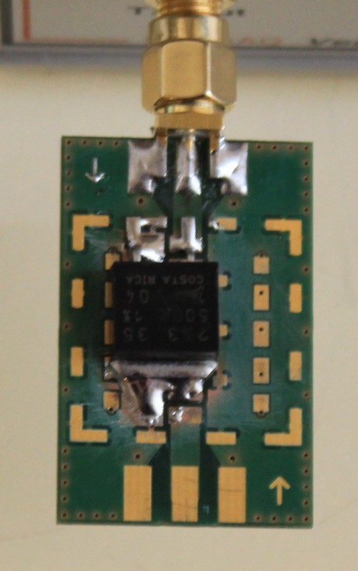
In this first example I would like to design a 50Ohm-Dummyload capable to dissipate 10 Watts – the resistor I have chosen for this task is a Bourns PWR263S-35-50R0F – which is specified for 35 Watts (with proper cooling). This resistor is a thick-film resistor, because we want to keep parasitics inductances low and has a tolerance of 1%.
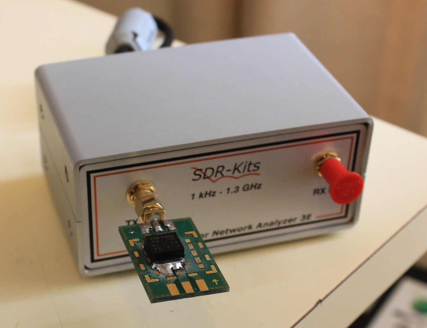
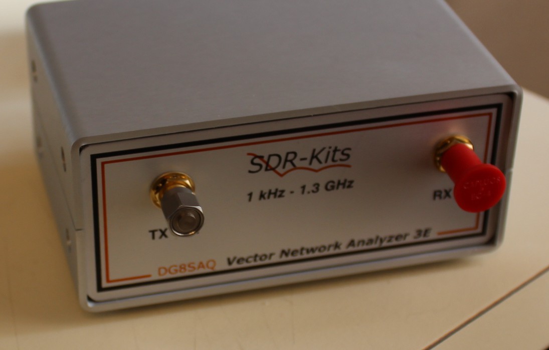
To measure the performance I attached the DIY-Dummyload to a VNWA3E Networkanalyzer
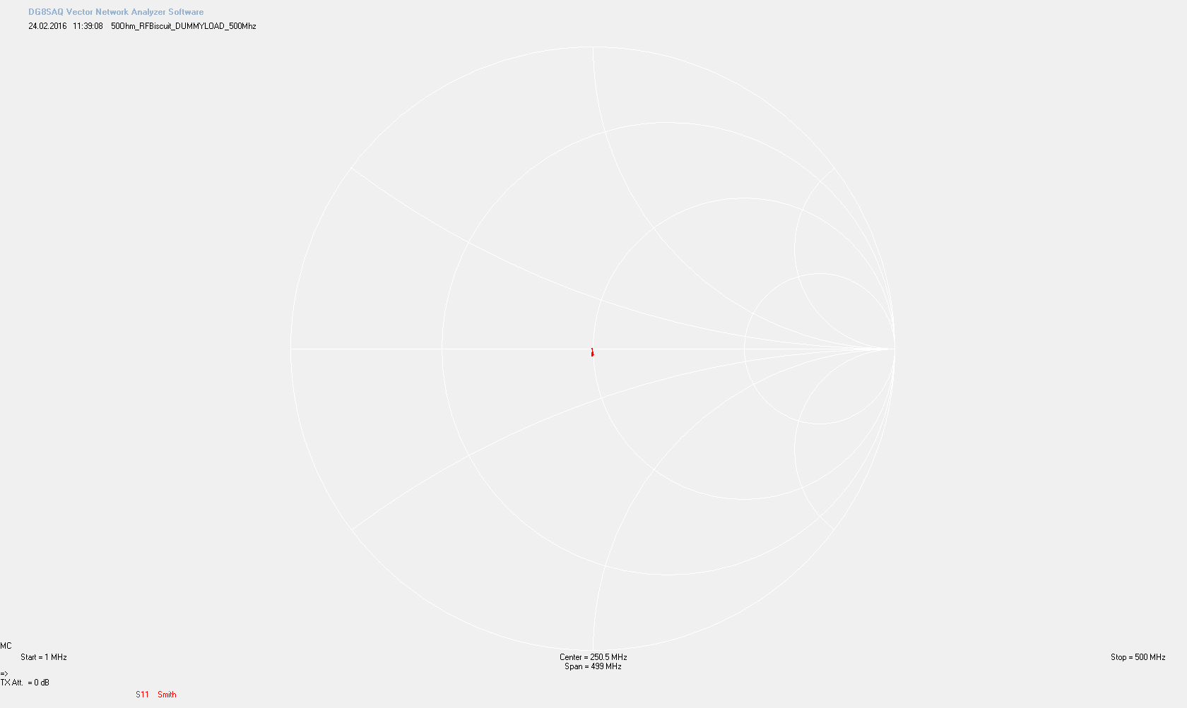
above 500Mhz the parasitic capacitance of the RF Biscuit starts to show – but depending on your application such a result might be considered still as good-enough.
 Let’s compare this result to a commercial 50Ohm-Termination
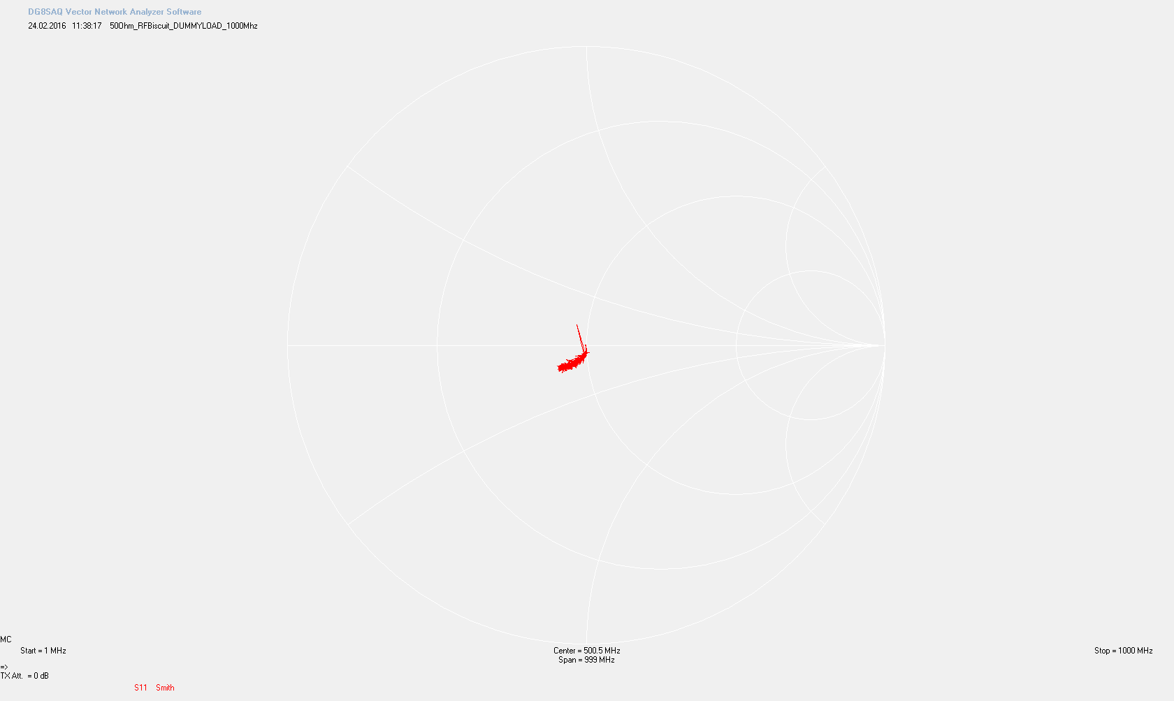
 The following Smith Diagramm shows the 50Ohm-Termination in the Frequencyrange of 1-1000Mhz:
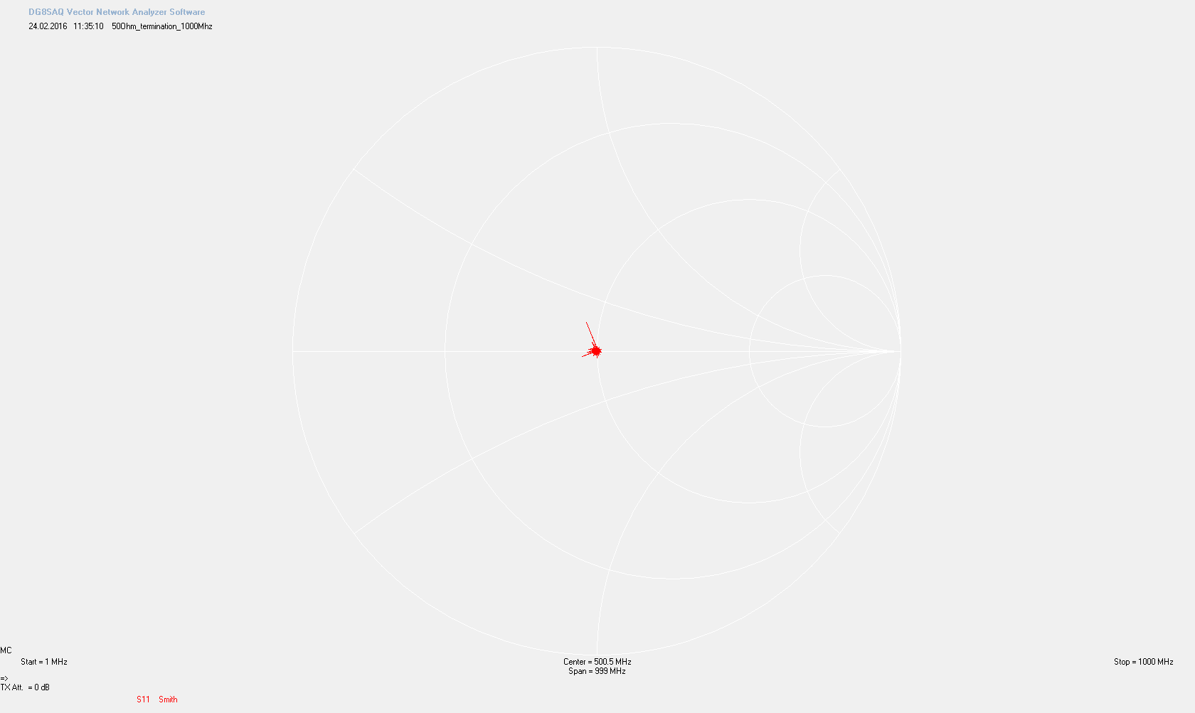
In this Diagramm you can see that the dot is a bit broader – which can be explained as the VNWA3E is less accurate above 500Mhz . You can also see spurs which are releated to the measurement device and which are not part of the characteristics of the 50Ohm Termination.
I will update this part with an evaluation of the thermalperformance of the DIY-Dummyload.
Discussions
Become a Hackaday.io Member
Create an account to leave a comment. Already have an account? Log In.