georg ottinger
-
#rfbiscuit – Use Case 2: Attenuator
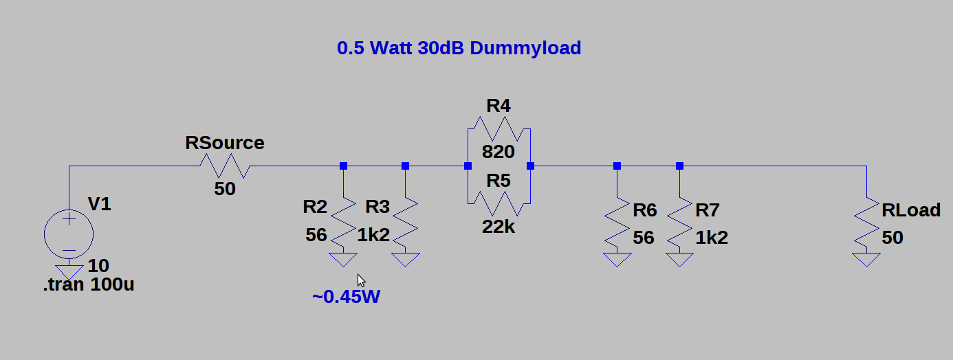
03/20/2016 at 09:37 • 0 commentsFor the second use case I wanted to try design a 30dB DIY-Attenuator. I used this attenuator calculator (german) to calculator the resistors for a PI-configuration at 50 Ohm input and output impedance. I needed to place 53.3 Ohm and 789.8 Ohm resistors – in order to generate the right resistor values – I choose to put for each resistors, two resistors in parallel. The needed values I calculated with the tool pointless-resistance, which automatically searches the values of the E-Series for suitable candidates within a defined tolerance.
for 789.8 Ohms – I used 820 parallel with 22k – which results in 790.5 Ohms
for 53.3 Ohms – I used 56 parallel with 1k2 – which results in 53.5 Ohms
![]()
In the Simulation you can see that major share of the power has to be dissipated by the lower resistor close to the input. The 0603 Resistors I am using have a power rating of 100mW which is the limiting factor. 100mW translates to 20dBm which is enough for my experiments. (see Watt-dBm converter) – But a more clever solution would be to use different resistors in physical size, because in our schematic only R2 has to dissipate the majority of excess power. For example a 1218 Resistor would be sufficient enough for 1Watt / 30dBm. (See resistor sizes and power dissipation)
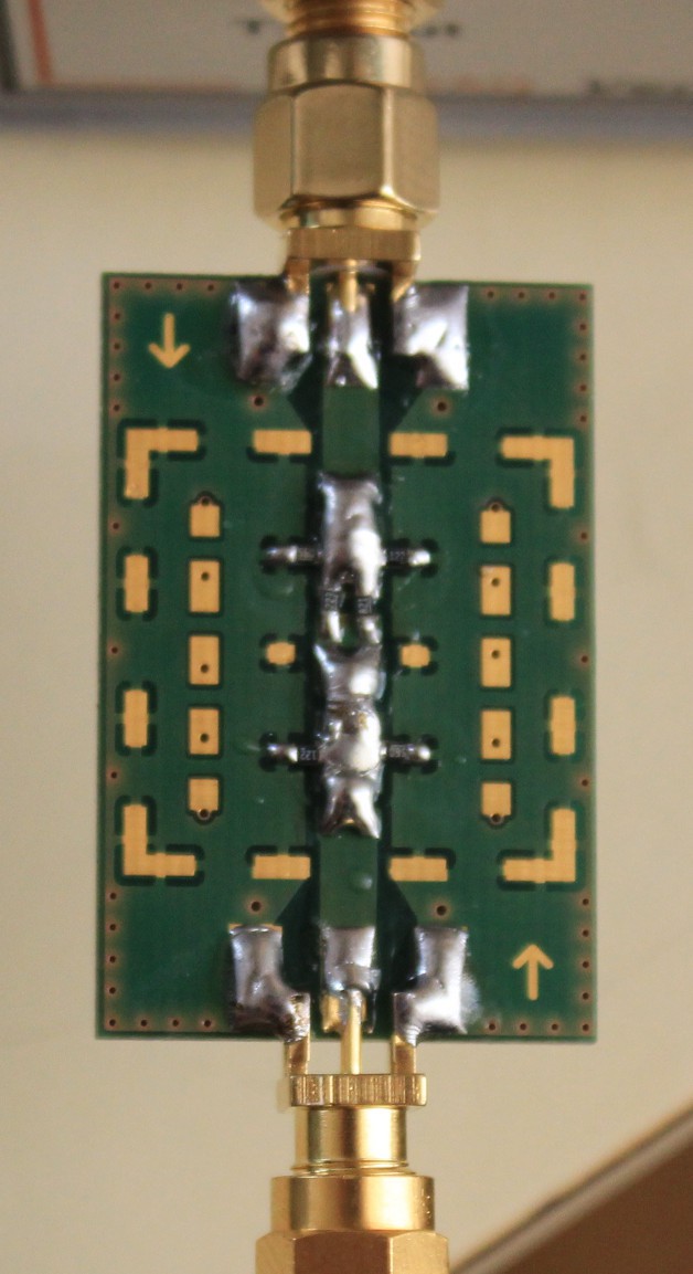
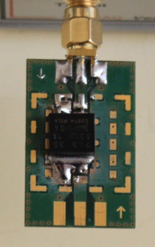
After the math it is time for solder – and the result looks like this:
![]()
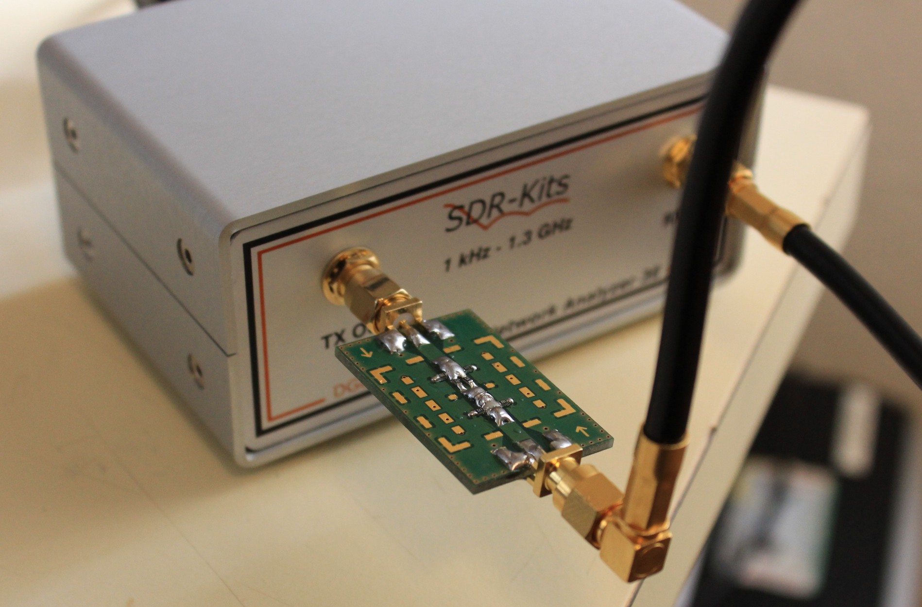
And to measure its performance lets connect it again to the VNA:
![]()
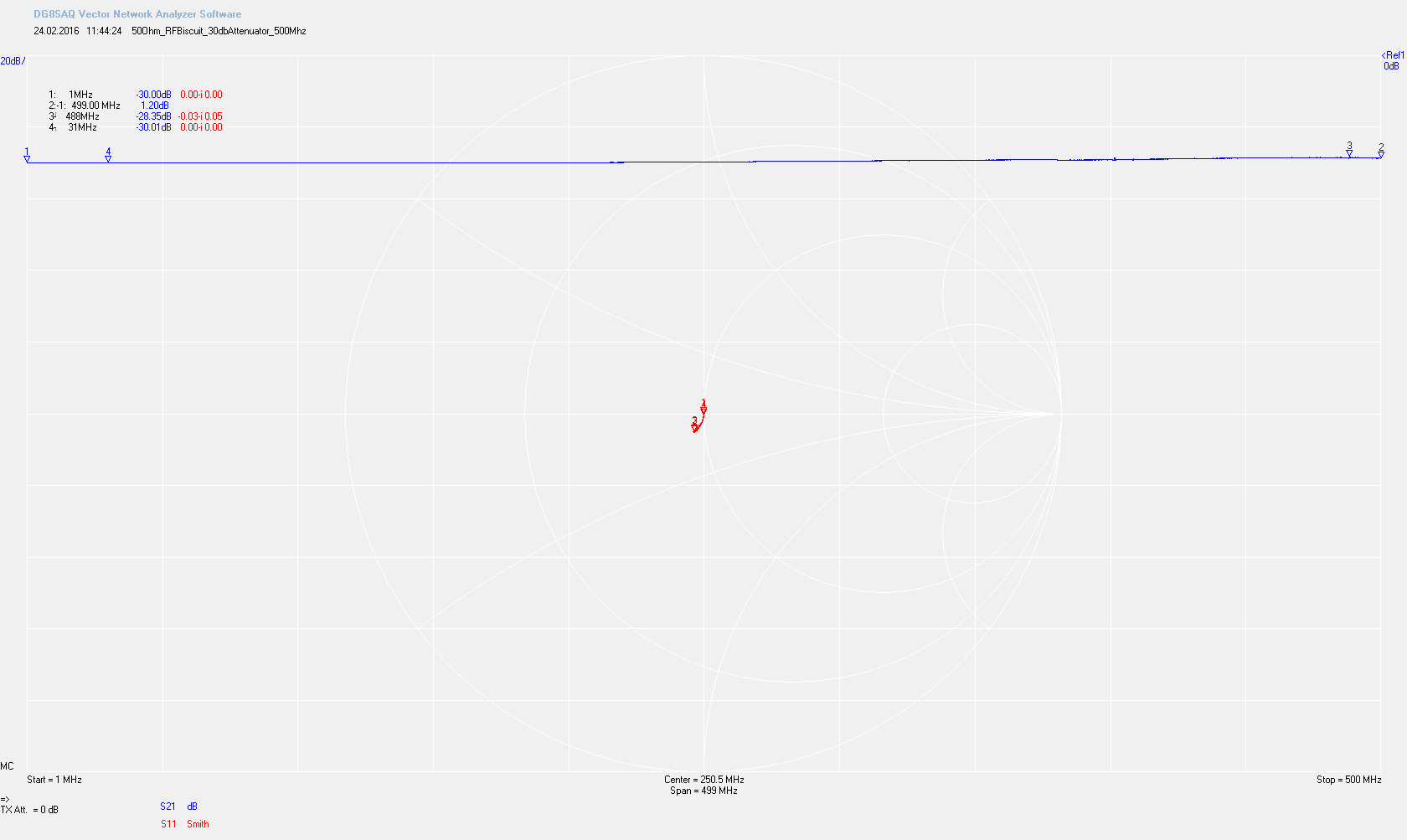
Measurement results in the Range 1-500 Mhz:
![]()
We are pretty close to our 50 Ohm impedance. The flatness of the attenuation ranges from -30.01 dB to -28.35 dB. The parasitic capacitance already start to show up a little.
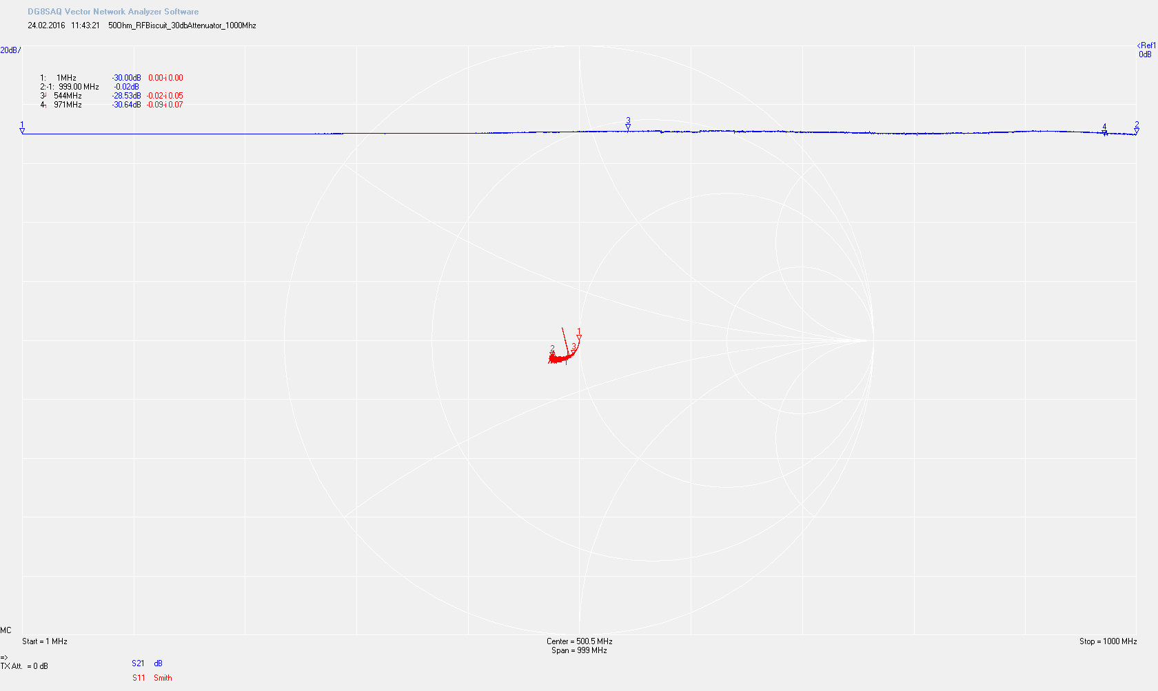
Measurement results in the Range 1-1000 Mhz:
![]()
The parasitic capacitance are getting stronger and flatness is -30.64 to -28.53dB
I conclude that the attenuator is good enough for my “lowfi” experiments. But lets compare it to a commercial available attenuator (specified up to 3Ghz).
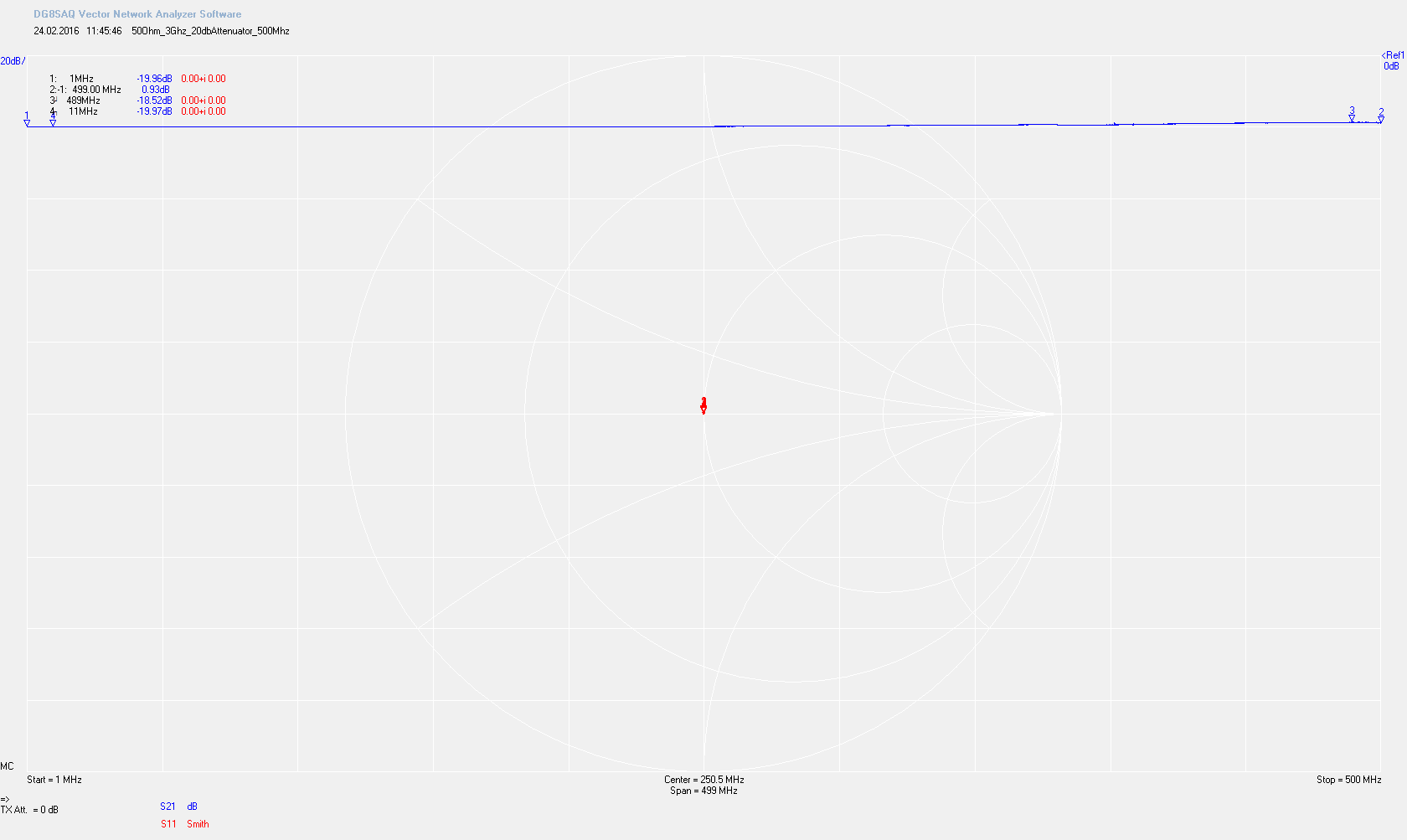
commercial -20dB 3Ghz Attenuator (1-500Mhz):
![]()
The impedance is just a spot (the vertical lines that are visible are only the markers). Flatness is: -19.97 dB to -18.52dB
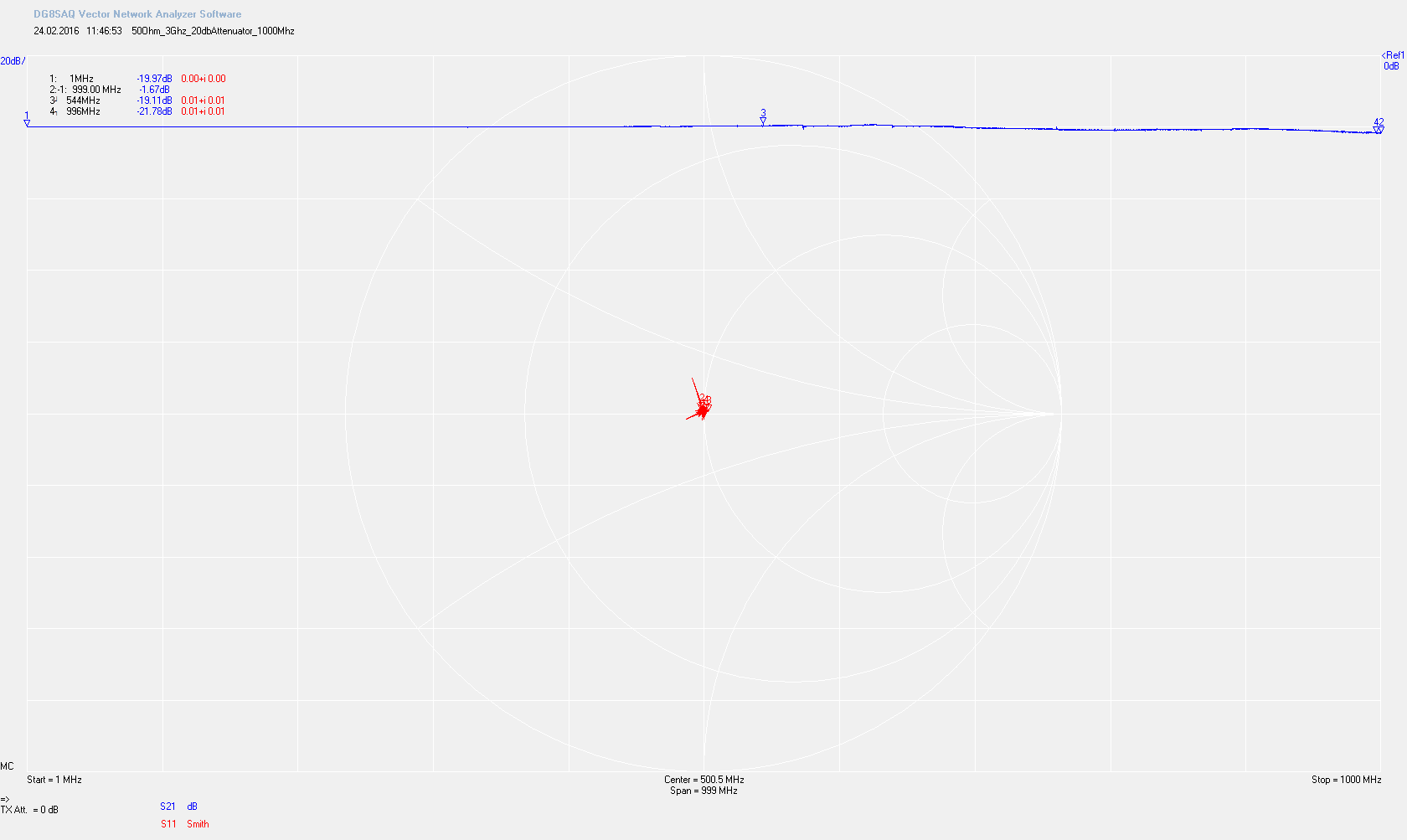
commercial -20dB 3Ghz Attenuator (1-1000Mhz):
![]()
The impedance is still spot on – although you can see spurs which are related to the measurement. The spot is a bit broader because the accuracy of the VNA degrades a little above 500Mhz The flatness is: -19.11 dB to 21.78 dB
-
#rfbiscuit – Use Case 1: Dummyload
03/20/2016 at 09:24 • 0 commentsIn this first example I would like to design a 50Ohm-Dummyload capable to dissipate 10 Watts – the resistor I have chosen for this task is a Bourns PWR263S-35-50R0F – which is specified for 35 Watts (with proper cooling). This resistor is a thick-film resistor, because we want to keep parasitics inductances low and has a tolerance of 1%.
![]()
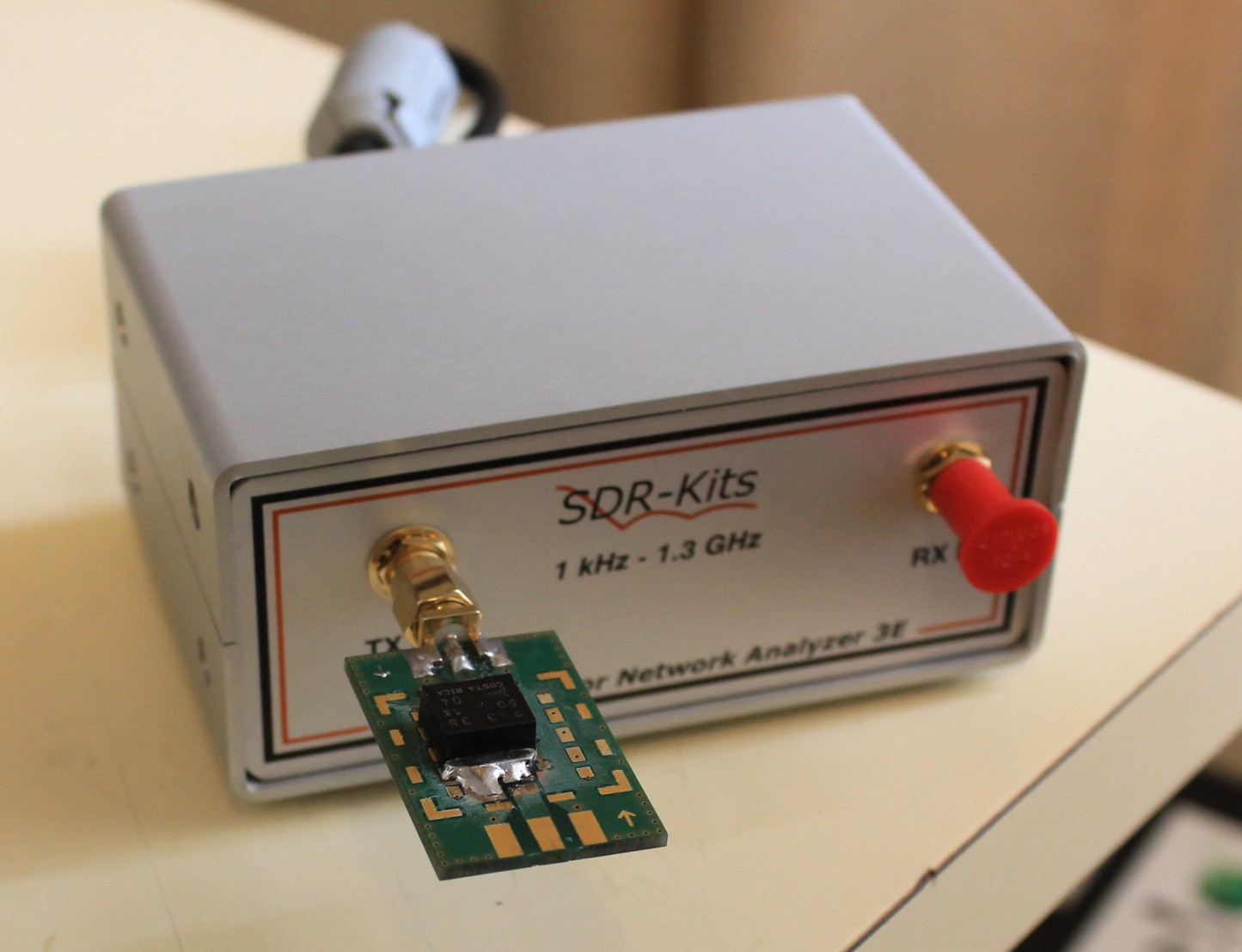
To measure the performance I attached the DIY-Dummyload to a VNWA3E Networkanalyzer
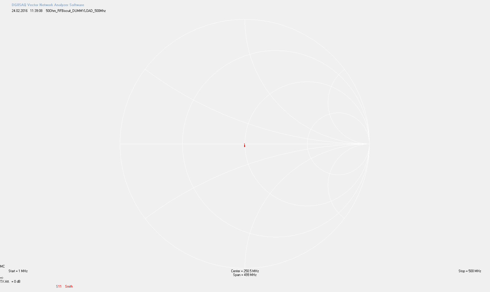
In the frequency range from 1-500Mhz the DIY-Dummyload shows up as a dot in the Smith Diagramm. Exactly what we want.![]()
![]()
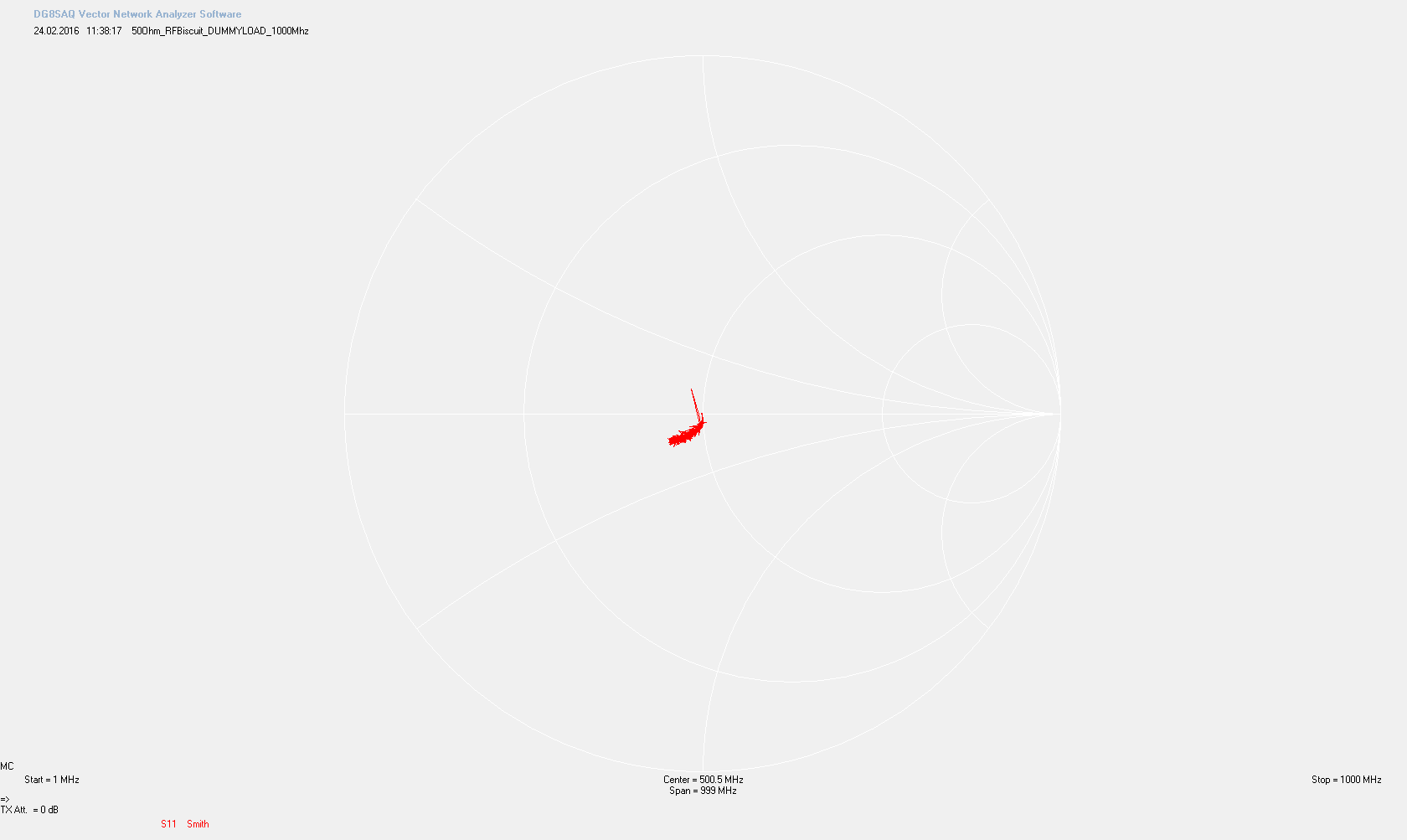
above 500Mhz the parasitic capacitance of the RF Biscuit starts to show – but depending on your application such a result might be considered still as good-enough.
![]() Let’s compare this result to a commercial 50Ohm-Termination
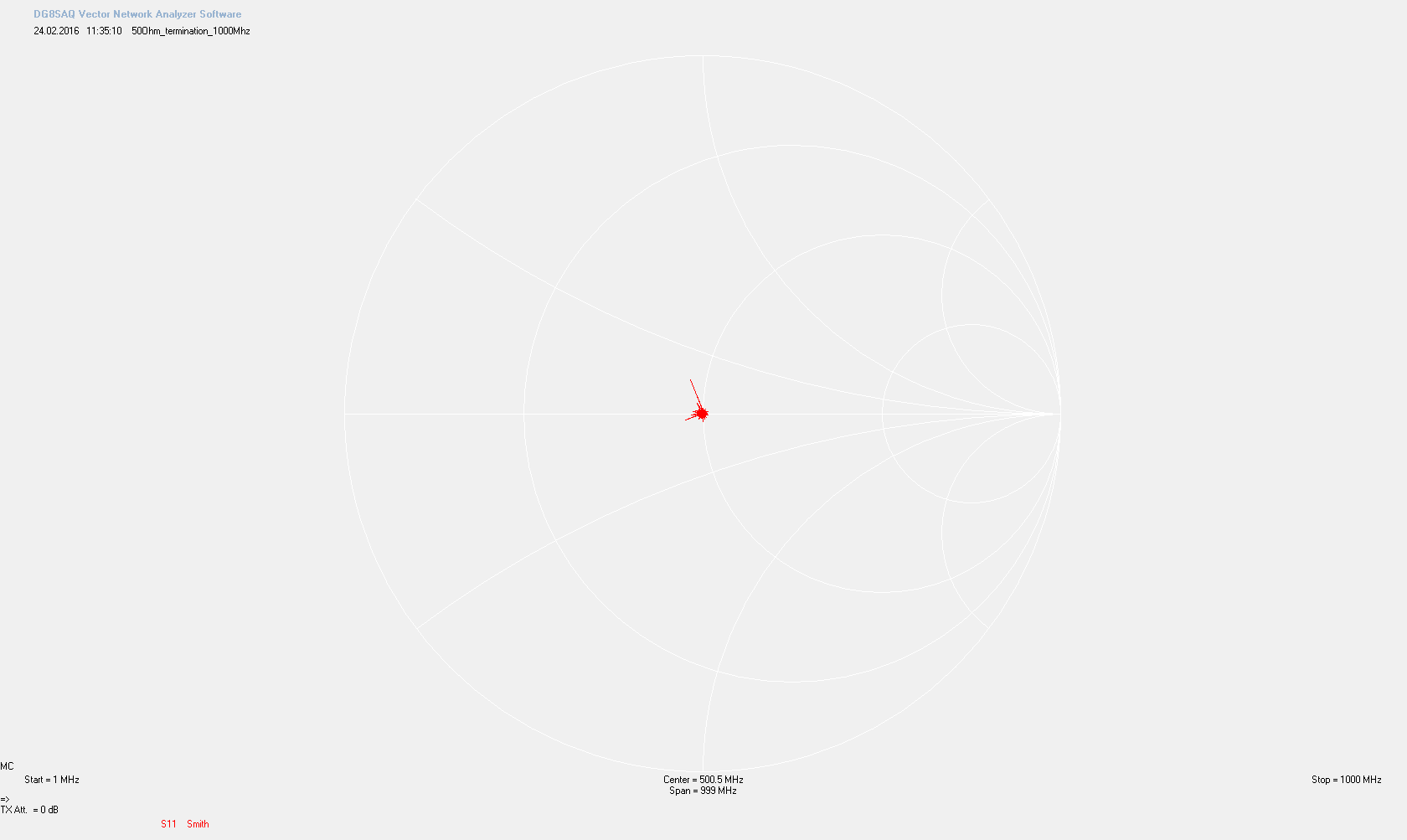
Let’s compare this result to a commercial 50Ohm-Termination![]() The following Smith Diagramm shows the 50Ohm-Termination in the Frequencyrange of 1-1000Mhz:
The following Smith Diagramm shows the 50Ohm-Termination in the Frequencyrange of 1-1000Mhz:![]()
In this Diagramm you can see that the dot is a bit broader – which can be explained as the VNWA3E is less accurate above 500Mhz . You can also see spurs which are releated to the measurement device and which are not part of the characteristics of the 50Ohm Termination.
I will update this part with an evaluation of the thermalperformance of the DIY-Dummyload.
RF Biscuit
A small, simple, low-cost, versatile PCB that can be used to make filters, attenuators, amps, dummy-loads the DIY-way