-
Kos v2.0
11/21/2022 at 10:48 • 0 commentsIn Kos 1.0 I used a pro mini board for the microcontroller, because that was the traditional way at the time, and it had the most widespread support. But it's an old microcontroller and the board is hard to get and expensive during the chip shortage, when the chip fabs are busy churning out chips for the missiles, so I decided to revisit this design and this time use something modern – the Raspberry Pi Pico, which is both cheap and available, at least until the military designs catch up with the new chip technology.
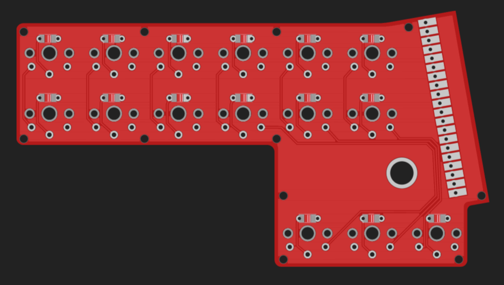
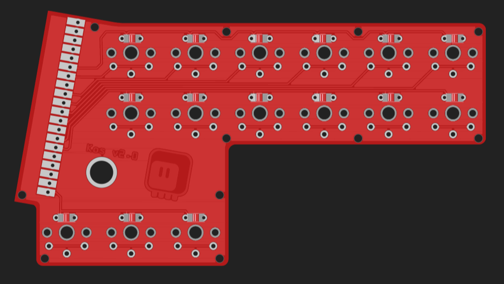
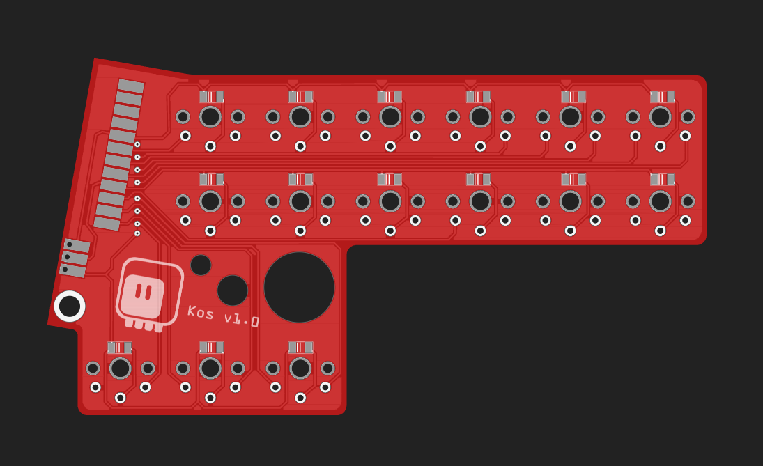
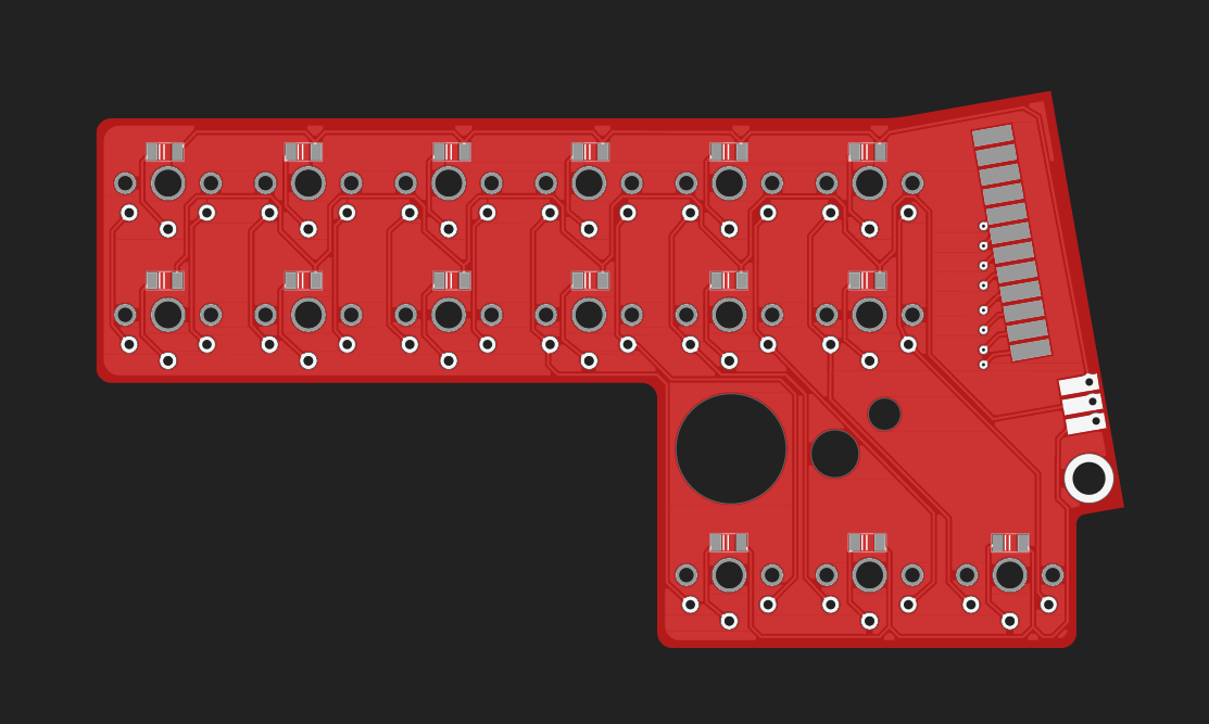
With more pins available on each side, and with the board being mostly symmetrical, I could simplify the design greatly. I no longer need to connect the rows across the two halves, and I can simply have all horizontal traces on one side, and all vertical traces on the other.
![]()
![]()
As with the previous versions, you need two of the PCBs to make one keyboard, and you connect them by soldering a pro micro in the middle. Since QMK now supports RP2040, there shouldn't be any problem with the firmware, but I will probably use the CircuitPython code I already wrote for the other stenotype, or maybe try and get the USB HID steno protocol working. The Pi Pico opens a lot of possibilities, even putting a simplified version of Plover together with the dictionary on the board itself, and emulating a HID keyboard should be doable.
As usual, the PCBs and parts should arrive within two weeks.
-
Kos v1.0
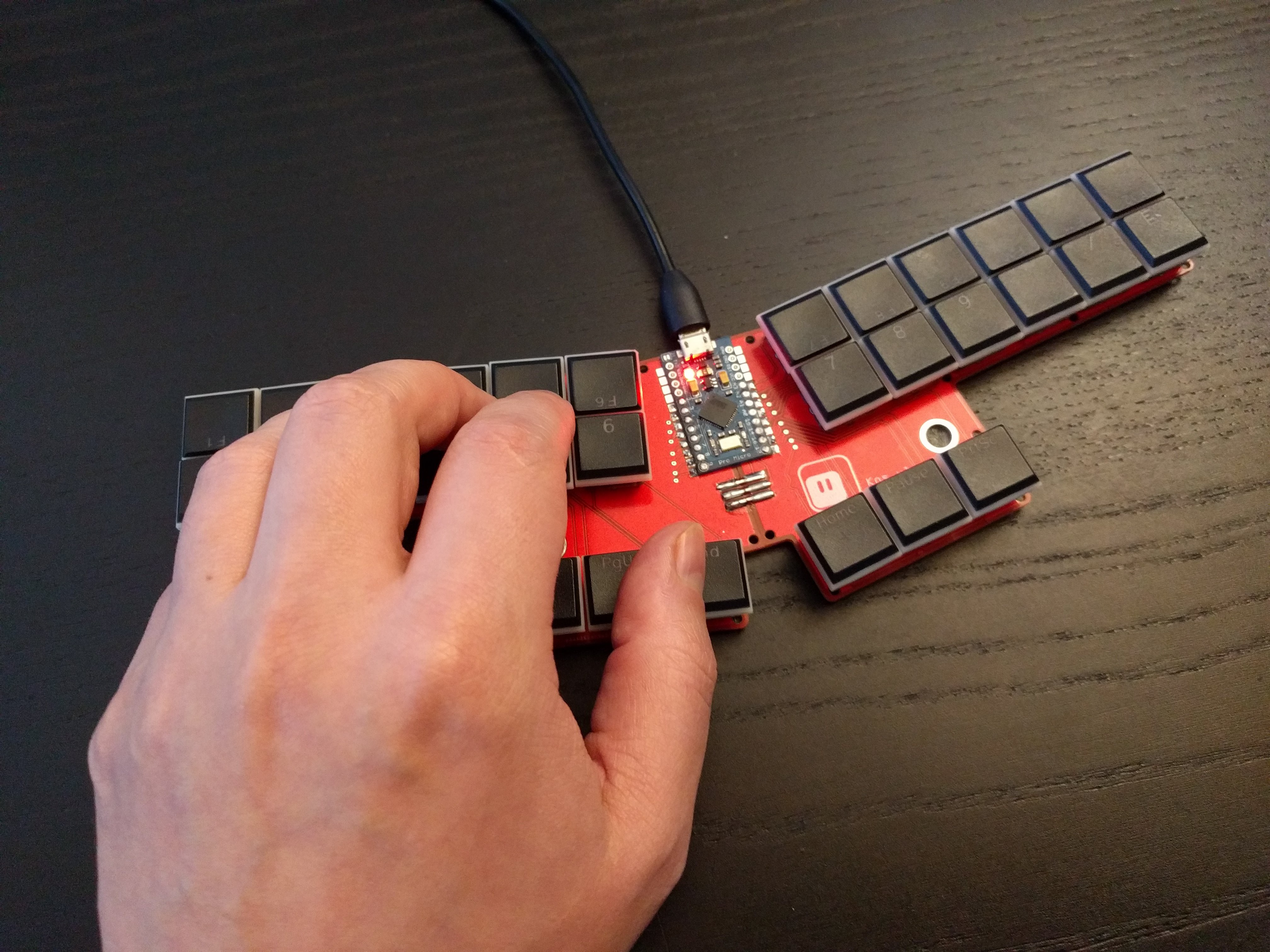
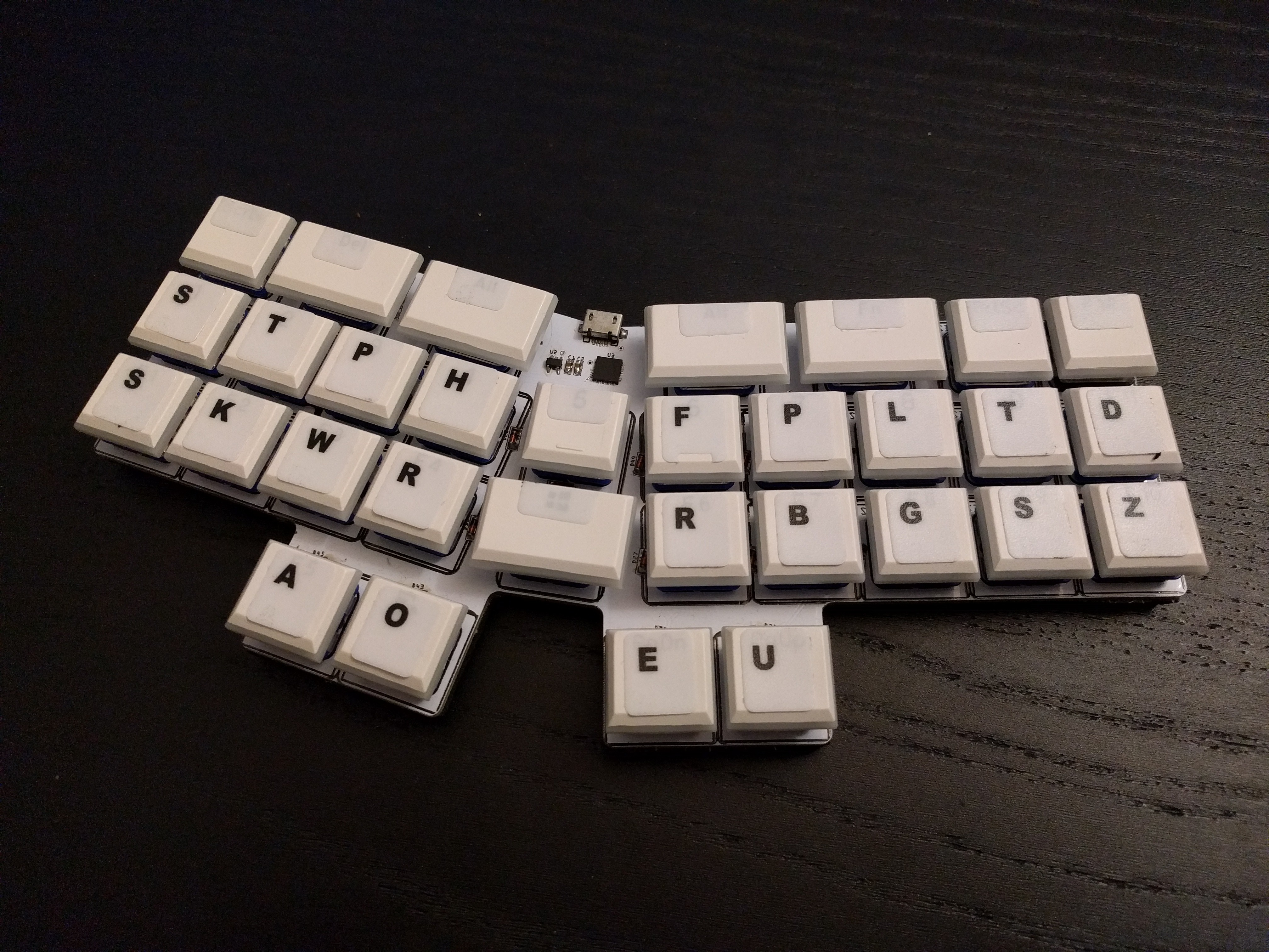
12/06/2021 at 17:16 • 0 commentsWe have the first version of Kos working!
![]()
This time, instead of my favorite SAMD21 I userd a standard Pro Micro with Atmega32u4, and programmed it with QMK. This is to make this as easy to reproduce as possible, because the goal is to have an affordable steno machine with enough keys to do stenotyping in Polish.
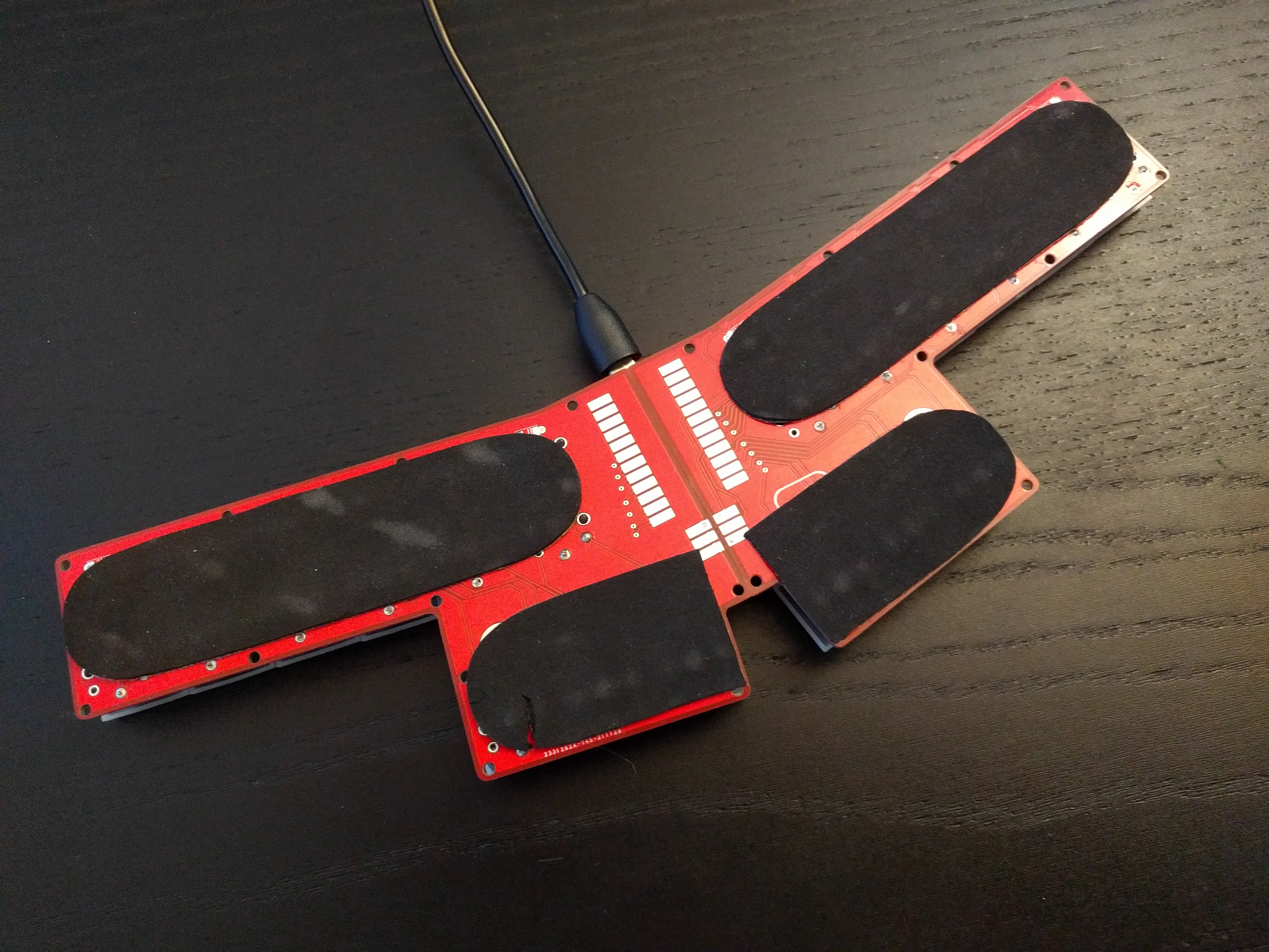
The back has some nice foam stickers, so that it won't scratch the desk:
![]()
The design files and QMK configuration are at https://github.com/deshipu/kos-steno
-
Stenotyping in Polish
11/24/2021 at 22:10 • 0 commentsStenotyping somehow never caught up in Poland, and while there are several systems of stenography, there is none for stenotypy. But that just means there is an opportunity!
Krzysztof Smirnow describes his quest to bring Polish to Plover, the open source stenography engine. However, because Slavic languages tend to have a lot of sounds, a regular stenotype, like the one I made, is not up to the task. More keys are required.
So after a short exchange of e-mails, I sat down and tried to design a PCB for a stenotype that would be suitable for Polish, and at the same time not too expensive and easy to assemble at home. I came up with this:
![]()
![]()
The idea is that, since you have to order multiple PCBs anyways, I can save on the PCB size by only designing half of it, and then designing the other half on the back side. Then you take two of the, join together, solder a Pro Micro on top, add the diodes and switches, and you are ready to go!
Unfortunately, a back-of-the-envelope calculation shows that even if you make two of them at once (which saves you some money, because the keycaps come in packs of 60, enough for two), they still cost about $45. Sure, that's not the $3000 you would pay for a commercial stenotype, but still more han you'd spend on something you try and discard.
I'm still going to make one, just to see if I made any mistakes.
-
Real Steno
11/22/2021 at 20:15 • 0 commentsI finally got back to this project and rewrote the code for it, so that it now acts the same as commercial stenotypes, one called "Gemini PR" to be specific. It turned out to be much easier than I anticipated, mostly because CircuitPython has grown a lot of the features needed for it in the mean time. The code looks basically like this:
import keypad
import usb_cdc


class Steno:
    def __init__(self, matrix, cols, rows):
        self.matrix = matrix
        self.keypad = keypad.KeyMatrix(rows, cols)
        self.width = len(cols)

    def run(self):
        report = bytearray(6)
        report[:] = b"\x80\x00\x00\x00\x00\x00"
        pressed_count = 0
        event = keypad.Event()
        while True:
            while self.keypad.events.get_into(event):
                y, x = divmod(event.key_number, self.width)
                key = self.matrix[y][x]
                if event.pressed:
                    byte, bit = divmod(key, 7)
                    report[byte] |= 1 << (6 - bit)
                    pressed_count += 1
                else:
                    pressed_count -= 1
                    if pressed_count == 0:
                        usb_cdc.data.write(report))
                        report[:] = b"\x80\x00\x00\x00\x00\x00"
That's it. There is also a boot.py to enable the second serial for data (and disable the REPL and disk unless a key is pressed when connecting it):
import usb_cdc
import usb_hid
import storage
import board
import digitalio


row = digitalio.DigitalInOut(board.SCL)
col = digitalio.DigitalInOut(board.MOSI)
col.switch_to_output(value=1)
row.switch_to_input(pull=digitalio.Pull.DOWN)

if not row.value:
    storage.disable_usb_drive()
    usb_cdc.enable(console=False, data=True)
else:
    usb_cdc.enable(console=True, data=True)
usb_hid.disable()

row.deinit()
col.deinit()
And of course the key matrix definition:
import board
import usteno
from micropython import const


ROWS = (board.SCL, board.AREF, board.D6, board.A4)
COLS = (board.MOSI, board.SCK, board.A0, board.MISO, board.A3, board.A5,
        board.TX, board.A2, board.A6, board.A1)


_FN = const(0)
_N1 = const(1)
_N2 = const(2)
_N3 = const(3)
_N4 = const(4)
_N5 = const(5)
_N6 = const(6)

_S1 = const(7)
_S2 = const(8)
_TX = const(9)
_KX = const(10)
_PX = const(11)
_WX = const(12)
_HX = const(13)

_RX = const(14)
_AX = const(15)
_OX = const(16)
_X1 = const(17)
_X2 = const(18)
_R1 = const(19)
_R2 = const(20)

_PW = const(21)
_X3 = const(22)
_X4 = const(23)
_XE = const(24)
_XU = const(25)
_XF = const(26)
_XR = const(27)

_XP = const(28)
_XB = const(29)
_XL = const(30)
_XG = const(31)
_XT = const(32)
_XS = const(33)
_XD = const(34)

_N7 = const(35)
_N8 = const(36)
_N9 = const(37)
_NA = const(38)
_NB = const(39)
_NC = const(40)
_XZ = const(41)


MATRIX = (
    (_N1, _N2,   0, _N3,     0,   _N4,   0, _N8, _N9, _NA),
    (_S1, _TX, _PX, _HX,   _X1,   _XF, _XP, _XL, _XT, _XD),
    (_S2, _KX, _WX, _RX,   _X2,   _XR, _XB, _XG, _XS, _XZ),
    (  0,   0, _AX, _OX,     0,   _XE, _XU,   0,   0,   0),
)


usteno.Steno(MATRIX, COLS, ROWS).run()
Then you just need to start Plover, configure the right serial port in settings/machine (it was /dev/ttyACM0 for me), select Gemini GP as the machine type, and you are ready to steno!
-
Version Two
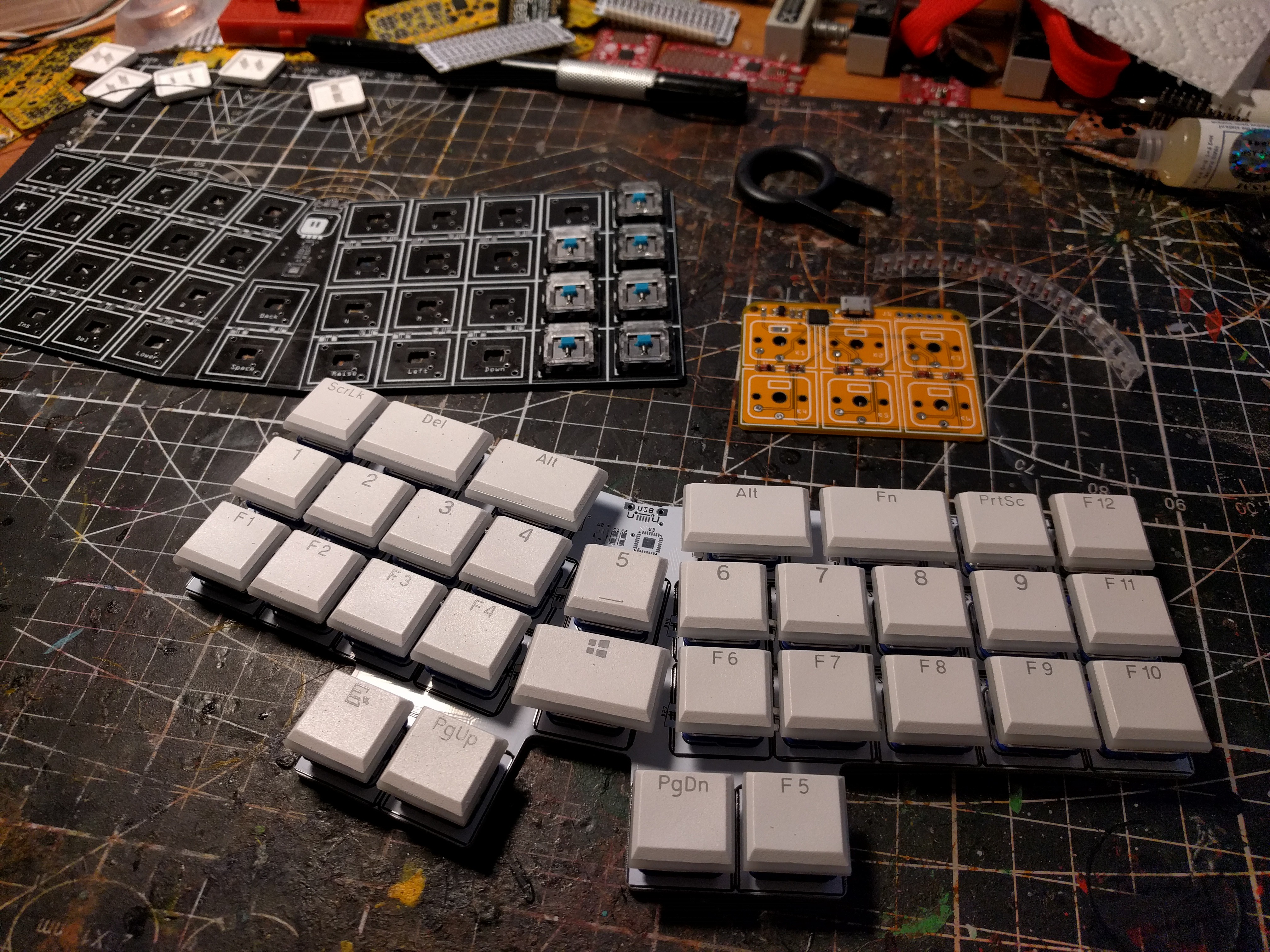
02/22/2021 at 23:10 • 0 commentsAs you might have guessed from the previous log, I decided to try and make another stenotype. This time with a little bit more experience from my low-profile keyboard projects. Of course it's low-profile, and of course it runs CircuitPython.
![]()
I used blue Kailh Choc switches, because they are very light, with 25g springs. That is important, because you are usually pressing a lot of keys at once, and the forces add up quickly. The switches are linear, not clicky, but I think it's fine.
I used some keycaps I had left over from building other keyboards — mostly function keys and some random stuff like Print Screen or alternate Alt. I couldn't use keys with proper legends, because the letters repeat here, so I would need several sets. Instead I bought several sheets of stickers for "converting" your keyboard to a different layout. They look bad, but it works well enough for training.
Right now I programmed it as a keyboard to be used with Plover, but ultimately I want to make it work like real stenotypes, as a serial device. CircuitPython just recently had a se]cond USB CDC device added, so I can use that.
-
Soon...
11/25/2020 at 16:36 • 0 comments![]()
-
It's Alive, ALIVE!
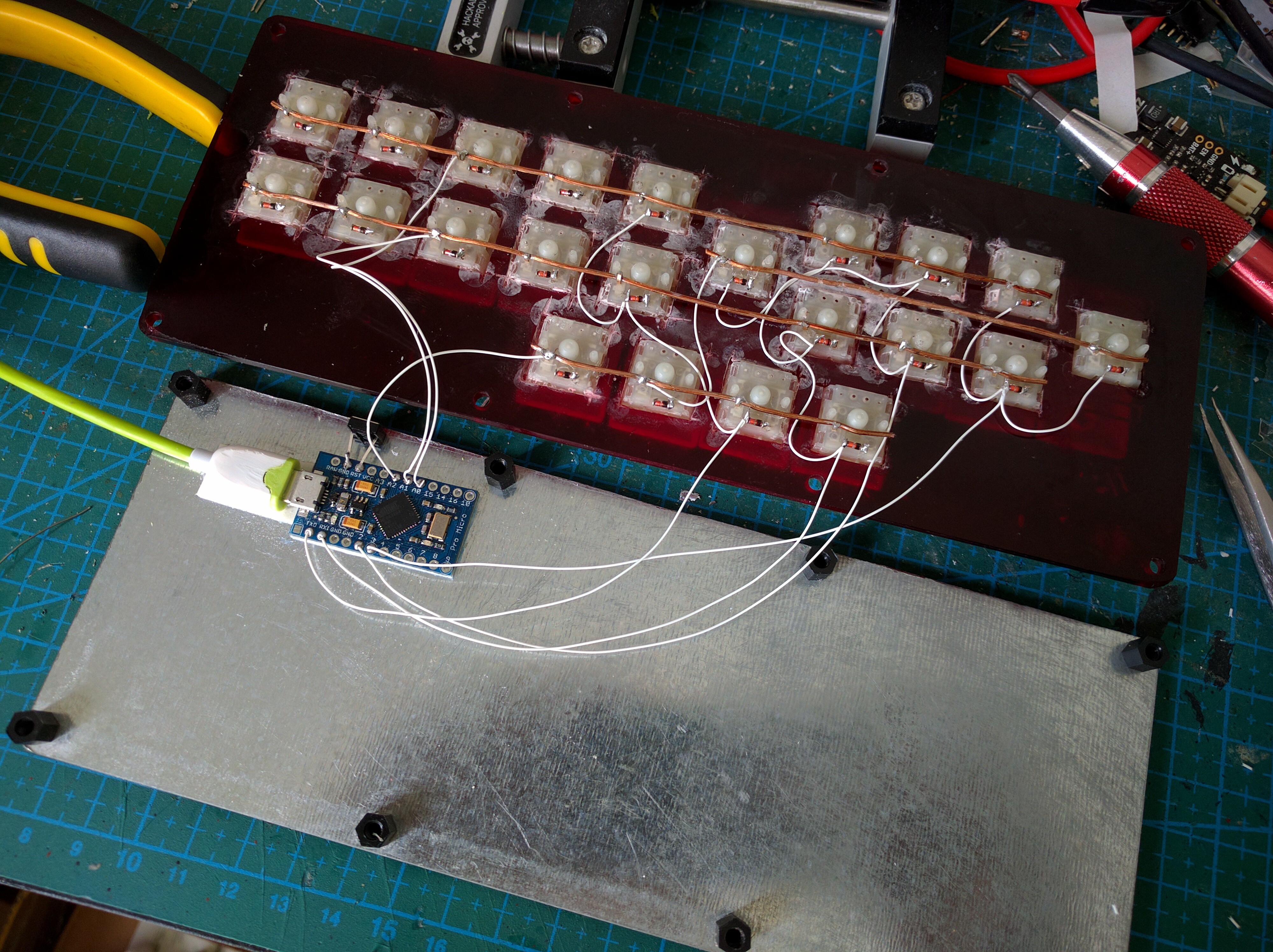
08/01/2017 at 15:44 • 0 commentsHaving cleaned the switches overnight, in the morning I started to work on the wiring. I used a two-sided tape to glue a Pro Micro to the base, added a USB cable (I had to file the plug a little to make it fit inside the keyboard), and started to add the wires and diodes.
![]()
I decided to use 3 rows and 8 columns, with the two large keys in the same row as the vowels on the bottom. This lets me return the row status as a single byte and makes the scanning quite fast.
For software, I used the same TMK keyboard firmware as in #Alpen Clack, with just two changes, one to the key map:
static const uint8_t PROGMEM keymaps[][MATRIX_ROWS][MATRIX_COLS] = {
  {
    {KC_W,    KC_E,    KC_R,    KC_U,    KC_I,   KC_O,   KC_P,    KC_LBRC},
    {KC_S,    KC_D,    KC_F,    KC_J,    KC_K,   KC_L,   KC_SCLN, KC_QUOT},
    {KC_Q,    KC_T,    KC_C,    KC_V,    KC_N,   KC_M,   KC_NO,   KC_NO},
  },
};
and one to the matrix functions:
/* Column pin configuration
 * col: 8
 * pin: PD0 PD1 PD2 PD3 PD4 PD7 PC6 PE6
 */
static void  init_cols(void) {
    // Input with pull-up(DDR:0, PORT:1)
    DDRD  &= ~0b10011111;
    PORTD |=  0b10011111;
    DDRC  &= ~0b01000000;
    PORTC |=  0b01000000;
    DDRE  &= ~0b01000000;
    PORTE |=  0b01000000;
}
static matrix_row_t read_cols(void) {
    return (PIND&(1<<0) ? 0:(1<<0)) |
           (PIND&(1<<1) ? 0:(1<<1)) |
           (PIND&(1<<2) ? 0:(1<<2)) |
           (PIND&(1<<3) ? 0:(1<<3)) |
           (PIND&(1<<4) ? 0:(1<<4)) |
           (PIND&(1<<7) ? 0:(1<<5)) |
           (PINC&(1<<6) ? 0:(1<<6)) |
           (PINE&(1<<6) ? 0:(1<<7));
}
/* Row pin configuration
 * row: 3
 * pin: PF7 PF6 PF5
 */
static void unselect_rows(void) {
    // Hi-Z(DDR:0, PORT:0) to unselect
    DDRF  &= ~0b11100000;
    PORTF &= ~0b11100000;
}
static void select_row(uint8_t row) {
    // Output low(DDR:1, PORT:0) to select
    switch (row) {
        case 0:
            DDRF  |= (1<<7);
            PORTF &= ~(1<<7);
            break;
        case 1:
            DDRF  |= (1<<6);
            PORTF &= ~(1<<6);
            break;
        case 2:
            DDRF  |= (1<<5);
            PORTF &= ~(1<<5);
            break;
    }
}
Unfortunately the Pro Micro doesn't break out any of its pin ports in whole, so I had to use multiple ports for the columns. I still have whole port B free, I might decide to add LEDs to the keys as a teaching help. For now let's keep things simple.
I don't have any CapsLock or NumLock keys, so the LEDs on the board are unused. I still placed it in such a place, that it is visible, just in case I might need them for something later.
Once I made all the connections and uploaded the firmware, I realized that 5 of the switches actually didn't survive the glue removal operation — they give no electrical connection. Fortunately I still had a bunch of switches left to replace them.
Now I'm going through the lessons at https://sites.google.com/site/ploverdoc/lesson-1-fingers-and-keys
-
Back on the Ring
08/01/2017 at 02:01 • 0 commentsI found this keyboard today in my drawer, and decided to try and revive it. The project got, um, paused indefinitely over a year ago, when I stupidly got superglue inside the key switches, and pretty much ruined them.
Today I decided to take a little bit of risk -- since the switches are broken anyways the way they are -- and applied a little bit of acetone to one of the keys. Lo and behold, it budged! A little bit of wiggling and scraping and removing the gunk from it, and it works almost as well as it used to. Great! Only 21 more to go!
Three hours later I pretty much have all the switches working (I had to replace one of them, but fortunately I still had some spares), and I am back to where the project was last time -- I have the rows of the keys soldered, and now I need to solder a diode to each key and then connect the columns, and connect everything to a Pro Micro.
-
Abort Mission
04/15/2016 at 12:58 • 5 commentsLast Monday I worked a little bit more on this keyboard. I decided to start on the wiring. I did the rows, and then I decided the keys are not sitting in their holes well enough. So I decided to do what I did with my previous two keyboards -- glue the switches in place.
Unfortunately, this time I used instant glue, and applied it when the keyboard was up-side-down, so that the glue got into the switches. Sure enough, they are all glued hard, and there is no force that could budge them now. I suppose I could try removing them, opening each and cleaning, but they would never again work as well as before, and I honestly don't have any stamina left to do it.
So I'm aborting this project, with a small possibility of reviving it if I get my hands on some spare switches again.
-
Backplate
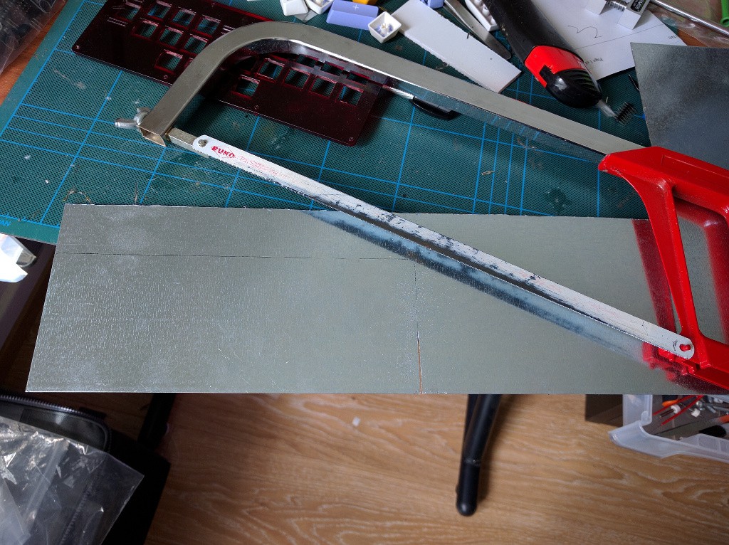
04/06/2016 at 10:55 • 0 commentsOK, the power of procrastination is immense. I already made the backplate. Started by cutting a rectangle from a piece of sheet metal. Who needs laser cutters when you have a hacksaw?
![]()
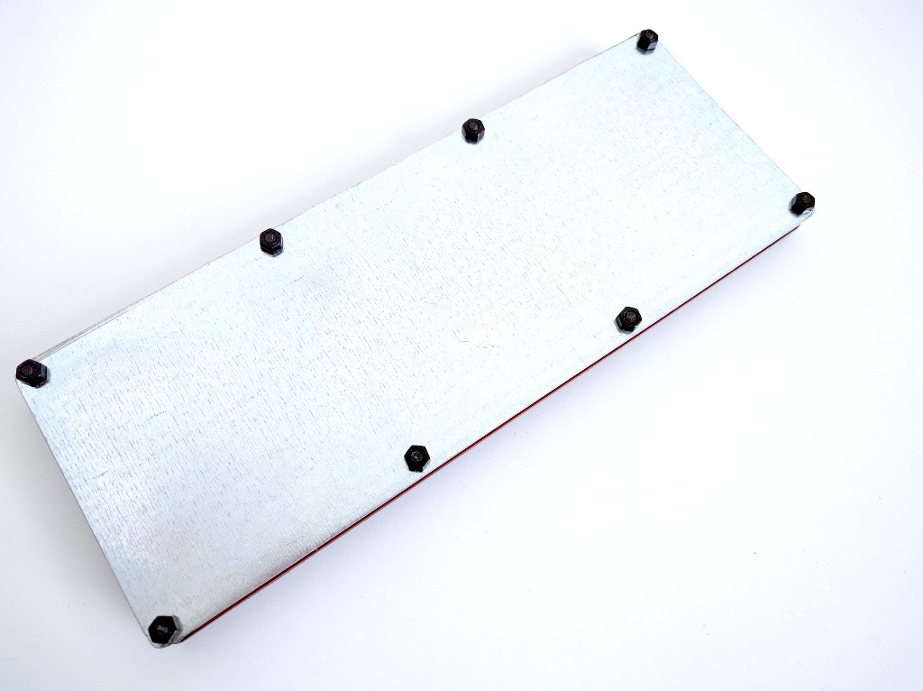
Next, I taped the two plates together and drilled the holes, then did some filing and dremeling to make the metal plate smooth and to round its corners. The result:
![]()
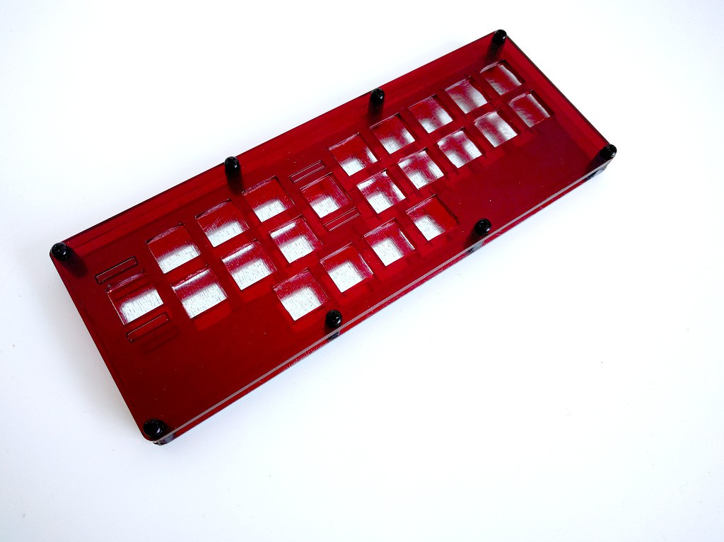
I used nylon spacers to connect the two plates together, cutting off the excess pieces of the bolts.
![]()
Next up: wiring.
 deʃhipu