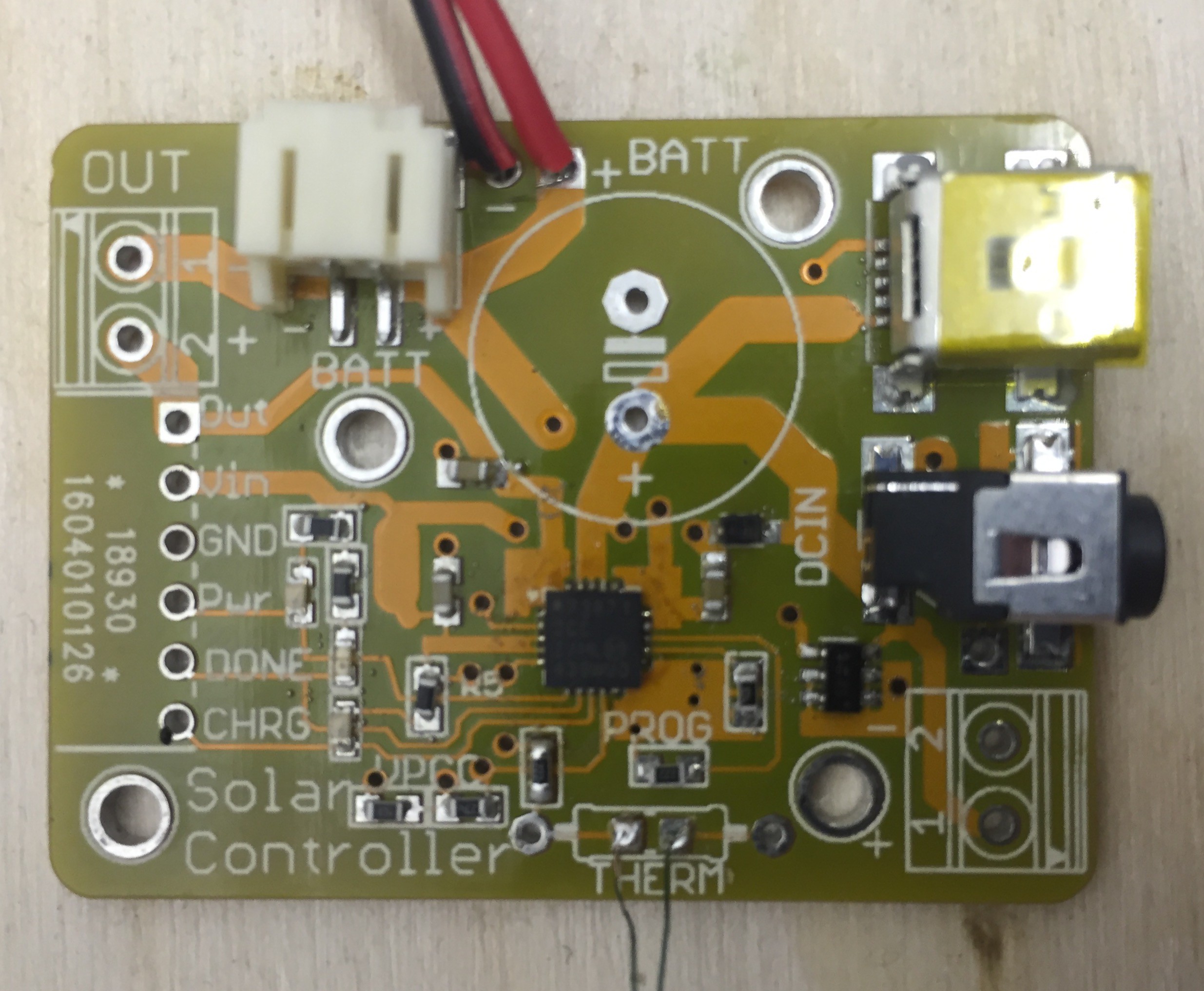
I got the nice yellow PCBs for the solar charger board from OSHPark, and soldered a board (on a hot plate).
The MCP73871 chip was really hard to solder. It is a 20 lead QFN, 4 x 4 mm with 0.25 mm wide pads on the bottom of the chip and a big ground pad in the center.
For my first attempt, I mixed some lead free solder paste with flux, and applied it to the pads on the board using a simple USB microscope to see. I then placed the chip on the board, and reflow-soldered it on a hotplate. Then I mounted the rest of the components, reflow-soldered it again, and tested it. It did not work properly. I suspect the soldering of the QFN chip. I tried touching it up with a soldering iron, but without success.
Today I made a second board. I cleaned the footprint with Isopropyl Alcohol (IPA), the applied solder paste to the pads on the board. Then I heated the board so that the solder paste melted on the pads. While the solder was liquid I poked at it so that there were no bridges. Then I took the board off the hotplate and let it cool. I had previously tried putting solder on the pads with a soldering iron, but I could not put solder on the exposed ground pad without creating a 'tip' where I removed the iron. I feared that this difference in height might ruin things.
Then I put a dab of solder flux paste on the ground pad on the board, and carefully placed and aligned the QFN chip on the solidified solder on the pads. I used the USB microscope again to see that the alignment was good.
Then I reflowed the board with the IC on it. When the solder melted, I again adjusted the position of the IC so that the pads were aligned (you can see a bit of the pads on the sides of the chip). Then I led the chip cool. Then I placed paste and the rest of components and reflowed the board.
Now this second attempt works (the LEDs light up properly, and it seems like it is raising the battery voltage properly, and only works when the thermistor is connected, like it should).
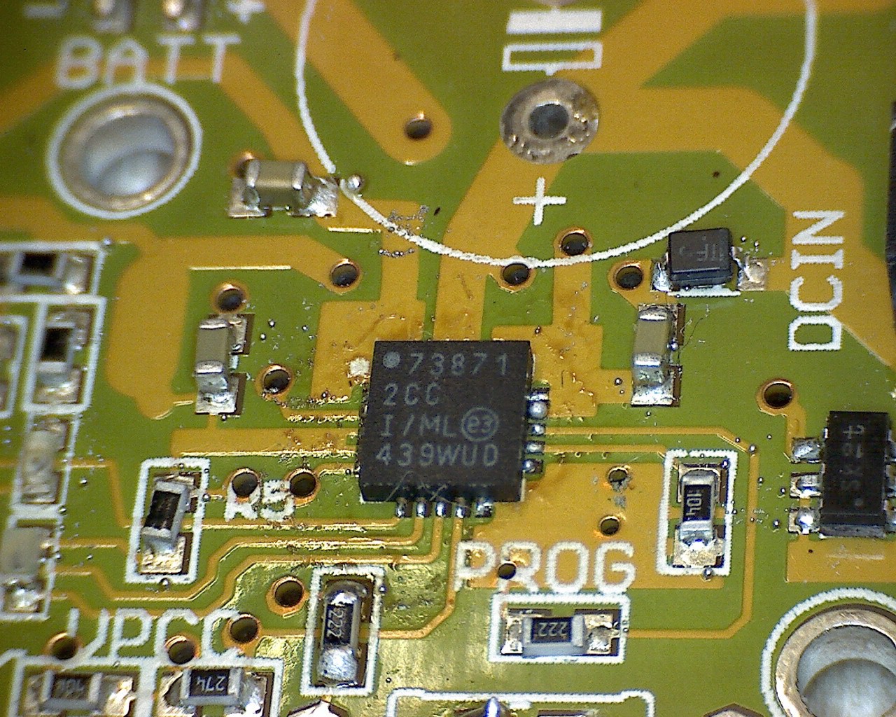
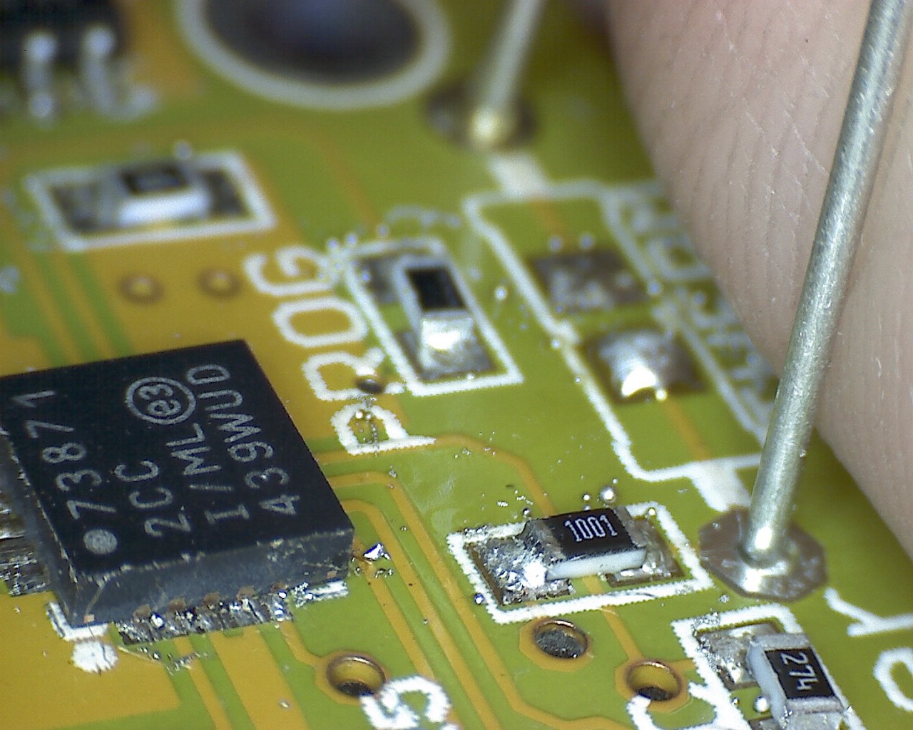
Here are two photos of the QFN chip through the USB microscope (an indispensable tool! I just bought it a week or so ago.). The resistors and capacitors are 0603-size (0.8 x 1.6 mm). The huge scary pinkish thing on the right side of the second photo is a part of my finger. The second photo is from my first, failed board. You can see that the pads are not perfectly aligned with the traces.
Discussions
Become a Hackaday.io Member
Create an account to leave a comment. Already have an account? Log In.