Base 3 -Ternary Computer from scratch.
Yes - No - Maybe? The goal is to completely step away from the normal binary system and investigate alternative computing systems.
Yes - No - Maybe? The goal is to completely step away from the normal binary system and investigate alternative computing systems.
To make the experience fit your profile, pick a username and tell us what interests you.
We found and based on your interests.
Ternary Presentation - final.odpSlides from the 2016 super conference with some gates to let people experiment with ternary using logisimpresentation - 3.77 MB - 11/11/2016 at 23:32 |
|
I am still actively working on this project, and I found another alternative to the Vishay part, the pin compatible MAXIM DG403. MAXIM were also kind enough to release libraries for use in my CAD software of choice. As soon as finals are over I will take some time and get the ALU pcb designed, etched, and populated :)
Thanks everyone for your suggestions and support! :)
Cheers!
~ThunderSqueak
A pile of parts I ordered finally came in! I now have some design choices to make, such as do I want to just hand wire this or should I make a proper PCB ... then if I do that, should I order it or etch it myself? Decisions Decision....
Here is a shot of some of the ICs that I am going to be using in the build.

I know I am a bit old fashioned, but there is just something fun and nostalgic for me when working with through hole components ^^;;
~Cheers!
Jessie
ThunderSqueak
While waiting for components to arrive, I have been doing some late night musing as to what functions I wish to implement into the CPU.
This is the list so far of opcodes, 0 through 13 (000 to +++), that I have been considering.
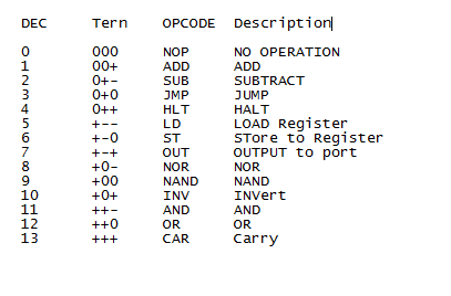
I want to attempt to keep the list down to 14 instructions, and am open to suggestions as to what should be removed from this list and have something more useful added in its place. LD and ST may be simplified to a MOV command freeing up one of the "slots".
This gives me a bit of a goal while doing the design, making the idea that much more concrete.
Another decision that has to be made is how many trits wide I want to make the system bus. The current thought is to make it 6, this is mostly due to cost of components on a hobby project :) The first 3 will be used for the opcode, the second set of 3 will be for the address that will be used.
Now to get back to calculus homework ^^;;
~ThunderSqueak
After doing the presentation at the HaD 10th anniversary convention I have been inspired to finish this project.
Parts sufficient to construct the ALU have been placed on order, I am going to be working with the vishay DG403 chip, and plan on building it in such a way that I will probably end up with a hybrid ternary/binary cpu.
I have removed the kleene logic table as it seems to confuse people in that it is more of a philosophical thing as apposed to a pure logic meant for use in a CPU ^^;;
The logic tables for doing math are as follows,
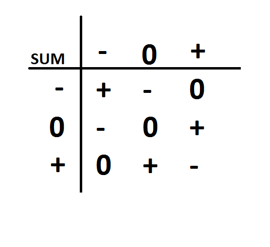
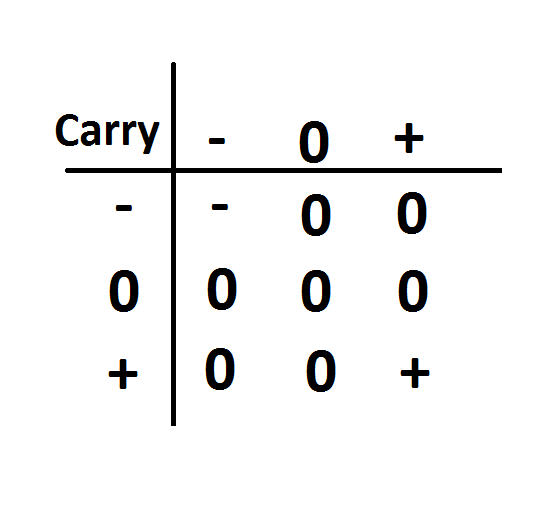
The chip in question appears to almost be ideal for the situation,

In other news, I have been toying with the idea of playing around with magnetic core memory, the final plan will most likely to use a transistor based memory system, however sometimes it is fun to look at older tech.
More to come after I receive the components and begin a proper build! :D
Thanks everyone for your support!
Now back to studying for midterms.... the joys of going back to school :)
~ThunderSqueak
Sad when life gets in the way of things, this summer has just been too busy to keep up with everything. Two jobs and a family among other things that take priority ^^. I will continue working on these projects as time and money permits and updating them here, but I guess I wont be in the next round for the hackaday prize. Thank you everyone for the skull :)
~Jessie
The project progress has been slow going. I am working a job and an internship right now. I have done a bit of experimentation with getting an adder implemented and have met with several issues. The totals if I added the numbers are different depending on which input I use for each number. With the hackaday prize deadline fast approaching and lack of components I may have to call this one for now and complete it at a later date when I can afford to get the proper parts shipped to Alaska.

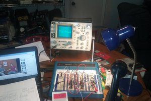
Quick snapshot of the breadboard right now.... I am playing with different ways of manipulating the voltage, in this case it is a basic "voltage divider" setup just to see if I can solve part of my input issue with addition.
The little circuit board at the top is an opamp "virtual ground" to split the 5 volt source that I am working with. The 6 switches let me input the voltage I want into each input, in this case -2.5v, 0v, +2.5v.
In other news:
I have been toying with another project idea and posted it at http://hackaday.io/project/1905-Toner%2FLaser-3D-Printer
Sorry I haven't posted much lately, just been busy ^^
I have already ordered some components to do a first build, still waiting on 1 more shipment to arrive. Until then, I have been working on different setups for building a functioning ALU. However, I am keeping logs and plan on releasing everything right here, including my thought processes. Even when things are wrong I have been including it. Its a great way to learn from mistakes and documents the entire project.
Also, I love the meaningful feedback people have! It leads me down even more rabbit holes. I plan to get some photos up and maybe even some video of the ALU when the time comes.
Thanks everyone for supporting me in this project :D
While waiting for parts to arrive I decided to do some random testing on my ipad in a little program called iCircuit. It is easy to use and lets you basically lay out subcircuits and create your own ICs. I do wish it had a larger parts library, but for what I was doing it was fine :)
I made various gates and added input, voltage, and output pins to each as needed then started doing little test scenarios. Below is a test of one of the circuits. I just hope it all works as easily when I use the real components that I ordered.
I just set the voltage to 6 volts to account for internal loss, I know it says 6.1 but using a slider on an ipad isn't an exact thing. ;)
Still, the basic building blocks all check out.
In other news, I have been deciding on a form factor for the new computer design. Most likely I will be going with stacked boards and spacers between them with a bus connecting each board.
~
ThunderSqueak
Since the parts are on order I decided to sit down and further hash out the logic. I had a rough idea on what I wanted to do (and ordered components to reflect the rough idea) but no definite plan. I took a few pictures of my notebook to show my thought process. :)
The best place to start is often at the beginning. I know binary logic and decided to start there. Below are a couple rough sketches and logic tables for a basic binary system. By using NAND and/or NOR gates in a binary setup you can construct any logic element that you want.
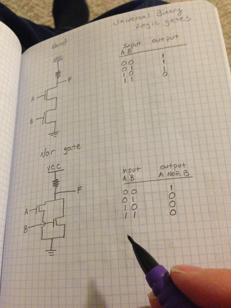
After some brainstorming I came up with a few rough ideas. I have considered both a 0/1/2 system and a balanced -/0/+ system. The later seemed easier to implement. I began with an idea of first using fets to get the job done. Using them I could easily control the voltage. It was late and I know I made mistakes on these, but I find it best to always write down ideas no matter how silly or wrong they are. Later when I look at them they may spark a correct solution. It has payed off more than once :)
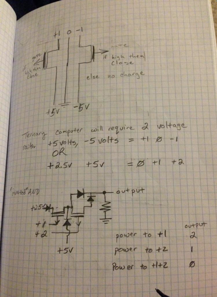
As you can probably see, I had no idea what I was really going for. So I went to sleep and had some nice dreams about riding my bike through the wonderful mountains of Alaska ^^;;

The above picture was taken by me while I went for a bike ride through Anchorage. It was a beautiful day.
I woke up the next morning with an idea, which I sketched down. I title all my ideas "random thought" when I am just scribbling. I am sure as this project goes you will notice my other strange habits while designing something. :)
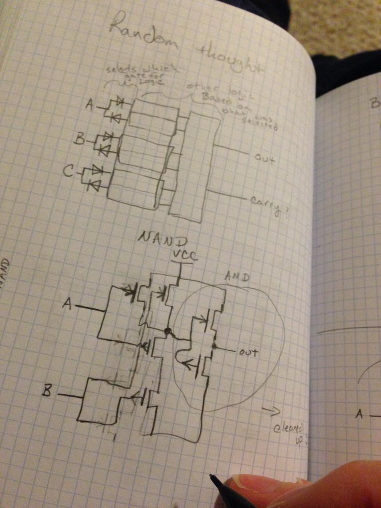
You can probably see the errors in this, if not YAY!
My goal was still in place. Design a NAND and a NOR gate to get the job done and figure out the basic logic. After dinner, I sat down again with my pencil and notebook. This was the result.
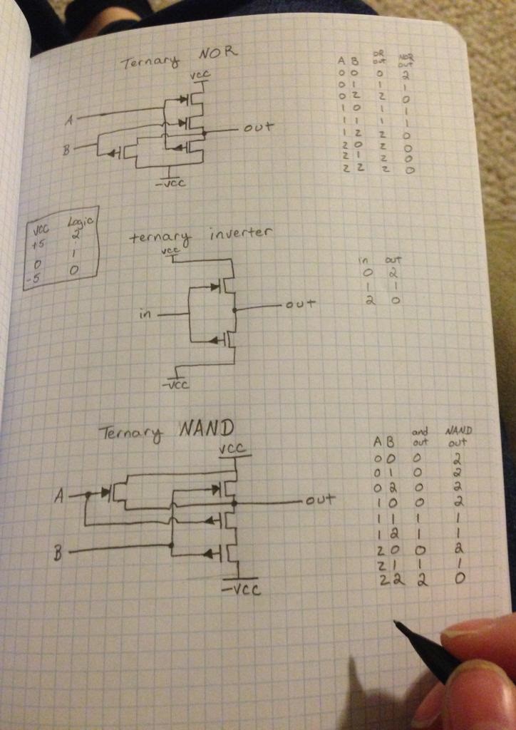
I hope this log of last nights dream and today's journey did not bore ya too much. I know I could use a circuit design program to do all this, but I still prefer to attempt to figure out the logic in my head. It's a great exercise for the brain, even if I do make mistakes and sometimes use incorrect notation. :) I am also toying with the idea of using an S-100 style bus for the build itself. That would allow me to change out modules and possibly extend the system when it is done. Now if the parts I ordered would just arrive I could test this to make sure it will work in the real world ^^;;
~Cheers!
ThunderSqueak
After a long day of reading and looking over parts catalogs I ordered some of the parts to begin this build. There goes a third of my budget! I have been looking at the best way to implement a basic logic system and the best way to design a ternary element. For me, most of my ideas are pretty outlandish when they are born. This one is no exception and I have never build nor designed a CPU before. I think it will be an amazing learning experience.
My goal is to design a non-binary based ternary element and then implement it into a simple CPU. The end result will be to do basic math as a proof of concept.
There are a few options available to me, one was just to see if I could design it all into an FPGA. I own a cyclone II that would lend itself to some experimentation.
https://pbs.twimg.com/media/BmmdOitCAAEYwue.jpg
I have been pouring over every bit of information I can find on machines that actually functioned, such as the Setun and would LOVE to find a copy of its schematic. It is a pity that so much technology is either lost or buried due to politics.
There seems to be a lot on ternary systems when you look at quantum computing, and if I succeed in my original goal I may look into adapting some of those ideas. Until then, its time to start from the ground up and see what can be done :D
Create an account to leave a comment. Already have an account? Log In.
That is actually a very interesting question. It is a little more complicated than it might at first seem. I have some notes over in my ternary computer emulator project:
https://github.com/tedkotz/ternary/tree/master/math
The first thing to consider is how much faster the number of possible operations expands in ternary than binary.
There are only 4 binary single input operations, and only 1 interesting one NOT. There are 27 single input ternary operations and you need at least 3 of them to be able to build the others.
For 2-input operations there are 16 binary ops and 19,683 ternary ops. it is a lot larger of a set to find useful operations in. And multiple operations that are all reasonable contenders for AND, OR. I generally prefer to replace AND with MINimum, OR with MAXimum and XOR with ADDition (single digit; i.e. mod 3), which is I think easier to conceptualize at scales down to binary or even up at base 10 and beyond.
For 3-input ops it goes to 256 binary and 7e12 ternary; 4-input 65k vs 4e38. Which when you consider a balanced ternary full adder could have 4 inputs and 2 outputs you start to envision the scale of ternary.
If you are talking actually doing binary operation on a ternary computer you could do Ternary Coded Binary storing one bit in each trit, wasting a state. MIN, MAX still mapping to AND, OR, but XOR is a little more complicated.
I've recently been back at this I did a bunch more work on my ternary CPU emulator over in my github.
https://github.com/tedkotz/ternary
I recently decided to drop down to a 27 trit word size and addressing memory in 9 trit trytes. I allocated 6-trits for opcode, but that is leaving a lot of space for expansion. It is currently at 33 instructions, but 11 of the immediate instructions could easily be removed, getting under the 3 trit 27 instruction limit and still maintain functionality, though with a penalty for more accesses to memory. the multiply instructions could also be written in software using the shift, add rotate and bitwise negate ops.
I've been toying around for a while with the idea of ternary computing. In order to get something off the ground I've recently started writing an emulator. Then I can start creating software and go back and fill in the hardware once I know what is really needed.
My plan is to eventually port a forth interpreter to it, in honor of DSSP on the Setun, maybe something like jonesforth. While I was stumbling around looking through others' thoughts I came upon this page.
I saw your instruction set and a couple comments came to mind.
1. Why only positive opcodes? I like limiting the opcode to 3 trits, but why not more fully use them.
2. There are a lot of bitwise logic instructions that might not be that useful. Ternary really needs a different set of base gates than binary. While binary only has 16 possible 2 input gates ternary has ~20k and the group you need is a little broader. For example, XOR is both conditional inversion and addition where as these are separate gates in ternary.
3. With no conditional instructions this won't be Turing Complete. Consider adding a way to branch conditionally (JMPGE). a sign flag trit in trinary is a lot more powerful than in a normal binary computer. I'm actually looking at making all my instructions conditional.
Being that memory is cheap in an emulator, I'm going 30 trits in a word (stored in 64 bits) and 27 registers.
You might want to consider creating a way to use binary memory at least temporarily to make it easier to get started. Building a simple translation buffer to go on the data and address lines shouldn't be too difficult.
Nice project, cool to see new interest in ternary computing and looking forward to your presentation at the 2016 Hackaday Super Conference!
For what it's worth, you may find my 2008 college research project on ternary computing useful: https://github.com/shellreef/trinary - especially the final report, which details the design of a simple 1484-transistor ternary computer. I also used a 3-trit architecture, but in TCA2 implemented only 3 opcodes (compare, load, branch), leaving the other two trits of the instruction tryte for the operand. LTspice circuit simulations included for unary/1-input logic gates (inverters, diodes, cycling, shift) and dyadic/2-input gates (TNAND, TNOR, TOR, TAND), a variety of flip-flap-flops (PZN, T, D, rising-edge triggered), 1:3 decoder, 3:1 multiplexer, and PCB layouts for a full-adder, tri-flops, memory, logic, etc.
Clever idea using the MAXIM DG403 high-speed analog switch, it looks like a good choice for ternary computing. In my project I used the old-school 4000 series CMOS chips, primarily CD4007 (complementary N- and P-channel MOSFET pairs) with pull-middle resistors (ala Mouftah 1974) and CD4016 as transmission gates. Explored other options briefly but agreed there's something about building computers out of discrete logic =). Would be interesting to see the performance of the DG switches with trinary logic. Good luck with your project can't wait to see what you come up with!
It looks like DG403 is the only way to go right now (in terms of ternary) - I designed dual ternary selector with 2xDG403 6 years ago and I'm selling it on Tindie for $16.66 each ;)
https://www.tindie.com/products/TRC/trimux-dual-balanced-ternary-multiplexerdemultiplexer/
It's working well on frequencies up to 1.5 MHz (Maxim is a little faster than Intersil) - problem is you need a lot of them in order to build a ternary computer :)
Rather than a three-state logic based upon "yes/no/maybe" or "true/false/null", would a three way comparison model be a bit more deterministic/tangible, eg " greater-than/less-than/equal" where logically a signal must be one and only one of these states (versus "maybe" state that could belong to either of the other states)?
I'm trying to imagine low-fi equivalent to such a 3 state system that would be analogous to the punch card for binary logic. The best I can think up is having an agreed upon "constant size" of a "hole punch" so that a given punch hole can be compared to this constant and return one of the three states. But this might introduce too much noise potential, with errors similar to the whole "hanging chad" issues.
Awesome project!
This has really got me thinking. I'm intrigued to know how you are making use of the 3rd state. In your intro you suggested 'maybe', but in fact there are a number of possible definitions - some more useful that others. For example you could have 'don't care' - not useful, 'not true or false', etc. Consider these statements.
John is happy
John is unhappy
John is not happy
'John is not happy' is not the same as 'John is unhappy'. It could mean for example, 'John is not happy, but he is contented' - which is neither happy nor unhappy. You can draw a Venn diagram to clarify it.
Great idea, someday I want to build a stochastic computer which uses noise instead of define logic levels.
BTW, your opcodes seem to oriented towards binary ALU functions (how does AND work in ternary?). It seems to me that you could make more powerful opcodes that would enable you to need fewer steps to process your data.
The well known "binary" operators AND, OR, NOT, XOR, etc, can be seen in a more abstract way.
In fuzzy logic, they work with multiple logical values, and therefore, they needed to find what these operators would be. And is actually really simple. The operator MIN(x,y) is the equivalent for AND, MAX(x,y) is the equivalent for OR and (BASE-1) - x is equivalent for NOT.
Using this ternary base, it would be like
--> AND(0,+) => MIN(0,+) = 0;
--> OR(-,+) => MAX(-,+) = +, and;
--> NOT(+) => 2 (BASE - 1, where BASE is 3 (ternary)) - 2 (decimal value of "+") = - (decimal value is 0);
He indeed can optimize the hardware, but I think that the architecture would stay almost the same.
@theo.j.sandstrom There's two ways of doing it.
The first is using the primitives. x XOR y = (x AND NOT(y)) OR (NOT(x) AND y)
The second one is using arithmetic. x XOR y = MAX(x,y) - MIN(x,y)
In binary there is no difference between rotation and inversion. since there is XOR, which can be thought of a "invertor/rotator of X, controlled by Y".
"If Y is zero then return X; otherwise return NOT(X), or inverted X"
or, as i prefer to think more
"Return TRUE if X and Y are NOT same; (otherwise return FALSE)"
But in ternary things are getting a bit more complicated; shift and negation is opposite operations, so there is exactly two ternary XOR's, with following truth tables:
ternary [binary] rotator(xor) is straightforward, MAX(x,y) - MIN(x,y). And it is controlled shift. first row is X-1, second is X, third is X+1, digits "-", "0", "1" come cyclic like after "9" you write "0" in decimal number "10":
1 - 0
- 0 1
0 1 -
ternary [binary] invertor(xor); same here, but first row now is X inverted around -: - is central, 1 becomes 0, and 0 becomes 1; second row is inverted around 0: 0 is central, 1 becomes -, - becomes 1; third row is inverted around 1: 1 unchanged, 0 becomes -, - becomes 0;
- 1 0
1 0 -
0 - 1
that's all easy things ;-)
Your machine is different than "normal" computers. Why make it do "normal" stuff? (Like arithmetic). "Yes / No / Maybe" is good for AI and fuzzy logic. Why not target those applications, where a "normal" computer struggles?
Forget doing math ... unless you want to learn base10 math like a human would. Leave that stuff to a conventional "co-processor".
You could try voice recognition / transcoder (speech to text) ... or a video classifier/target identifier/target tracker ... such as:
From a web-cam feed, you could classify, and (if moving) track, things from the video: grass, street, tree, bush, human, dog, cat, bird, car, truck, airplane, etc. Boundary pixels would be coded as "maybe". Identified pixels would be "Yes" to that ID, and "No" to everything else. Use a "normal" computer to transform RGB web-cam data into intensity/saturation/hue - since intensity will form a "gray scale" image that will be easier to define borders. The saturation and hue help with identification.
Yes, no, neither. Human brain, it feels good = do it, it hurts = do not and it neither feels good or bad is left.. It seems all our actions in life are based on this. Take away all our senses and what are we? Even the base element in the universe is positive, negative and neutral; the best program of all..
I like this effort, nice work.
Speaking of quantum computing, D-wave puts out some interesting info for those interested:
http://www.dwavesys.com/tutorials/background-reading-series/quantum-computing-primer
Although their claim to being a true quantum computer (where the time-cost of computation is so low, large combinatorial problems are solved in a fraction of conventional computing time) is contested - here's one:
Become a member to follow this project and never miss any updates
 cprossu
 Dave's Dev Lab
 Anderson Antunes
How to ternary Computers to boolean logic like And,XOR,OR and that sort of stuff.