 Bruce Land
Introduction
The intention is to introduce PIC32 into ece4760 in the
Fall 2015 semester. This is a start at understanding how the chip works.
The general way to learn this processor is to look at examples which
come with the MPLAB distrubution, Use the MPLAB help to understand the
plib syntax, Use the MCU datasheet to figure out the size and meaning of
the data field in each control register, then use plib.h, or the header
files it includes, to get the actual values of the constants used in
the examples for each data field. Then iterate. See links at the end of
this page.
Also refer to Tahmid's Blog for other experiments on the PIC32. Discussions with Syed Tahmid Mahbub have been essential for my learning to use the PIC32.
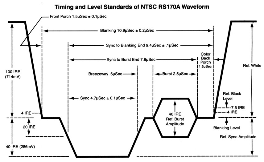
- NTSC video synthesis and output
--NTSC video is an old standard, but is still used in North America for closed circuit TV. It is fairly simple to generate a black/white NTSC signal. Also, the frame buffer for a 1-bit, 256x200 pixel image is only 1600 words (6400 bytes) of RAM. Chapter 13 of Programming 32-bit Microcontrollers in C: Exploring the PIC32 by Lucio Di Jasio was very useful. I used Di Jasio's method of generating sync pulses using one output-compare unit. Video is sent to the SPI controller using DMA bursts from memory (also similar to Di Jasio), but DMA timing-start control was implemented using another output-compare unit rather than chaining two DMA channels. This allowed easy control of video content timing. Timer2 is ticking away with an match time equal to one video line time. Ouput-compare 2 is slaved to timer2 to generate a series of pulses at the line-rate. The duration of the OC2 pulses (for vertical sync) is controlled by the Timer2 match ISR in which a simple state machine is running, but the pulse durations are not dependent on ISR execution time. Output-compare 3 is also slaved to timer2 and set up to generate an interrupt at a time appropriate for the end of the NTSC back porch, at which time the DMA burst to the SPI port starts. I got best video stability when the core is running at 60 MHz and the peripheral bus running at 30 MHz. The first example is just a bounding ball with some text. The example requires that the ascii character header file be in the project folder.
--The second example is a particle system explosion. Without doing any space optimization 1500 particles (along with screen buffer) use up memory. All the positions can be updated in every frame. Giving each particle a high initial velocity, and high drag makes a nice cloud.
-- The third example is a particle system fountain, which is a slight modification of the explosion. I optimized the point-draw and one ISR for more efficient execution. Frame update now takes 7.2 mSec. Video. The overhead for NTSC TV signal generation is about 5 microSec per 63.5 microSec line, or about 8%. - SPI control of a AD7303 DAC
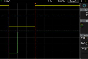
-- It is useful to get a serial channel running for fairly high speed peripherials. The first device I tried is an Analog Devices AD7303. It is a two channel, 8-bit DAC with buffered voltage output. The channels may be updated simultaneously or separately. Each channel write requires a two-byte transfer to the DAC. The first is a control byte, and the second is the channel data byte. The control byte specifies which channel will be updated as well as the update mode. Each two-byte transfer must be signaled by dropping the voltage on a SYNC pin before the beginning of the transfer, then raising it at the end. Like most microcontrollers the PIC32 SPI interface is simple enough to handle that direct register manipulation is probably the easiest, although the higher levelSpiChnOpenfunction also worked well. The SPI standard supports four clock phases. The microconctoller master has to match the requirements of the slave. This is often the most annoying part of getting SPI running. Careful analysis of the slave datasheet is required. The AD7303 requires the slave...


 Frank Buss
 Jithin
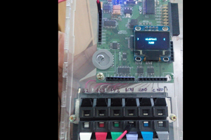
Right now the chip is in a MicroStickII. Soon on custom boards.