 shane kirkbride
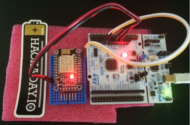
This log is about the basic UART communication between the ESP and the STM32. For the ESP I found an awesome open-source library from Jee Labs: https://github.com/jeelabs/esp-link. I've modified the source and I'll need to do make a branch to program the STM32 Chip eventually. But this post just covers the basics: Talking between boards or basic UART functionality to make sure both tool chains are working and both boards are working the way they should. The boards are shown below. You'll notice the UART is missing from the ESP board and it is now directly connected to the STM32 dev board. According to the datasheet: https://developer.mbed.org/platforms/ST-Nucleo-F446RE/ We can use Serial 4 to communicate easily to the ESP chip. Any of the other serial ports would work but I liked the fact that the pins were next to each other. This would reduce the risk of connecting the board wrong. The white Rx on the STM32 board connects to Tx output on the ESP and the yellow TX on the STM32 board connects to the RX input. The red and black wires are power and ground, respectively.
ESP-Link
When you install the esp-link it is important to keep in mind the paths. I installed it in the /examples directory:
shane@shane-VirtualBox:/opt/esp-open-sdk/examples/esp-link$but you'll still need to edit the make files to make sure they reflect the correct build path. This is around line 70. Here is the path that worked from me.XTENSA_TOOLS_ROOT ?= /opt/esp-open-sdk/xtensa-lx106-elf/bin/I also had to edit the ESP Tool build path around line 82 to the following:ESPTOOL ?= /opt/esp-open-sdk/esptool/esptool.pyNow that the make file is ready just go ahead and type 'make'. The output is as follows if it compiles correctly.
shane@shane-VirtualBox:/opt/esp-open-sdk/examples/esp-link$ make
Makefile:73: Using SDK from /opt/esp-open-sdk/esp_iot_sdk_v1.5.2
VERSION: esp-link master - 2016-05-31 19:57:37 - development
CC mqtt/mqtt.c
CC mqtt/mqtt_cmd.c
CC mqtt/mqtt_msg.c
CC mqtt/pktbuf.c
CC rest/rest.c
CC syslog/syslog.c
CC espfs/espfs.c
CC httpd/auth.c
CC httpd/base64.c
CC httpd/httpd.c
CC httpd/httpdespfs.c
CC user/user_main.c
CC serial/console.c
CC serial/crc16.c
CC serial/serbridge.c
CC serial/serled.c
CC serial/slip.c
CC serial/uart.c
CC cmd/cmd.c
CC cmd/handlers.c
CC esp-link/cgi.c
CC esp-link/cgiflash.c
CC esp-link/cgimqtt.c
CC esp-link/cgioptiboot.c
CC esp-link/cgipins.c
CC esp-link/cgiservices.c
CC esp-link/cgitcp.c
CC esp-link/cgiwifi.c
CC esp-link/config.c
CC esp-link/log.c
CC esp-link/main.c
CC esp-link/mqtt_client.c
CC esp-link/status.c
CC esp-link/task.c
make[1]: Entering directory `/opt/esp-open-sdk/examples/esp-link/espfs/mkespfsimage'
cc -I.. -std=gnu99 -DESPFS_GZIP   -c -o main.o main.c
cc -o mkespfsimage main.o -lz
make[1]: Leaving directory `/opt/esp-open-sdk/examples/esp-link/espfs/mkespfsimage'
Compression assets with htmlcompressor. This may take a while...
Compression assets with yui-compressor. This may take a while...
ui.js            ( 37%, gzip, 2804 bytes)
pure.css         ( 22%, gzip, 3820 bytes)
console.html     ( 35%, gzip, 1188 bytes)
style.css        ( 31%, gzip, 2276 bytes)
console.js       ( 46%, gzip,  956 bytes)
services.js      ( 42%, gzip,  768 bytes)
favicon.ico      ( 29%, gzip, 71360 bytes)
log.html         ( 39%, gzip,  908 bytes)
mqtt.js          ( 41%, gzip,  736 bytes)
wifi/wifiSta.html ( 35%, gzip, 1148 bytes)
wifi/wifiAp.js   ( 41%, gzip,  948 bytes)
wifi/wifiSta.js  ( 36%, gzip, 1664 bytes)
wifi/wifiAp.html ( 31%, gzip, 1152 bytes)
wifi/icons.png   (100%, none,  428 bytes)
services.html    ( 34%, gzip, 1164 bytes)
home.html        ( 37%, gzip, 1972 bytes)
mqtt.html        ( 36%, gzip, 1200 bytes)
96 -rw-rw-r-- 1 shane shane 95012 May 31 19:57 build/espfs.img
AR build/httpd_app.a
LD build/httpd.user1.out
Dump : /opt/esp-open-sdk/xtensa-lx106-elf/bin/xtensa-lx106-elf-objdump -x build/httpd.user1.out
Disass: /opt/esp-open-sdk/xtensa-lx106-elf/bin/xtensa-lx106-elf-objdump -d -l -x build/httpd.user1.out
FW firmware
ls -ls eagle*bin
  4 -rwxrwxr-x 1 shane shane   3013 May 31 19:57 eagle.app.v6.data.bin
320 -rwxrwxr-x 1 shane shane 326584 May 31 19:57 eagle.app.v6.irom0text.bin
 16 -rwxrwxr-x 1 shane shane  13496 May 31 19:57 eagle.app.v6.rodata.bin
 32 -rwxrwxr-x 1 shane shane  31728 May 31 19:57 eagle.app.v6.text.bin
-1333811629
1333811628
** user1.bin uses 374900 bytes of 503808 available
LD build/httpd.user2.out
-1071342667
1071342666
shane@shane-VirtualBox:/opt/esp-open-sdk/examples/esp-link$
Next put your serial connected ESP into programming mode and flash it using esptool:esptool.py --port /dev/ttyUSB0 --baud 460800 write_flash -fs 32m -ff 80m \
0x00000 boot_v1.4\(b1\).bin 0x1000 user1.bin 0x3FE000 blank.binA few notes on this command. If you are having trouble getting esptool to connect to the ESP8266 then try slowing down the baud speed. 460800 baud seems to work ok on little examples like 'blinky' but for bigger examples issues occur connecting and syncing. Also, it is important to make sure you are flashing the correct part of your memory. See this link for details:
http://www.espressif.com/en/support/explore/get-started/esp8266/getting-started-guide#
That was the hard part.
Next go here: https://github.com/jeelabs/esp-link#wifi-configuration-overview and configure the ESP. By now I hope you've realized that this is a really nice package to start with.
After you go through and configure the wifi correctly you can do OTA updates and iterate changes quickly. Below shows the ESP splash page for SunLeaf. I changedsome of the colors that Jee Labs uses because even though their code is awesome I didn't really like their color scheme.
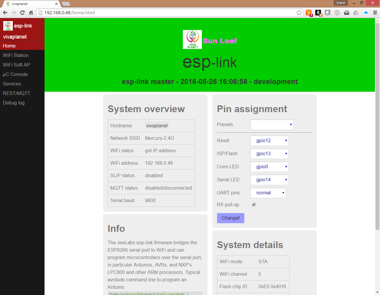
Aslo notice the menu bar on the side has a 'uC Console' page. This is the page we will use to talk to the STM32. So now tht you've set up the ESP it's time to dive into to the STM32 Nucleo board.
STM32 mBed.org
I am using the Nucelo-F446RE Development board. You can just get the drivers and plug the thing into your pc. It should recognize the file. When you open the file in good browser it will take you to the mbed.org site. This site has an online IDE that will allow you to flash the STM32. It is really nice as well.

There is a built in UART example that I started with on mBed.org. I wanted to send a character to the ESP and have the character display on my PC. I found a version of the code here: http://www.emcu.it/NUCLEOevaBoards/U2andU1onL152/U2andU1onL152.html and I modified it to use on my board.
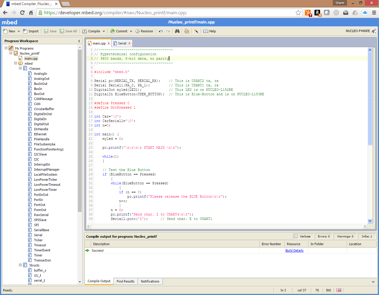
For completeness here is the actual code:
//------------------------------------
// Hyperterminal configuration
// 9600 bauds, 8-bit data, no parity
// for the F446RE only
//------------------------------------

#include "mbed.h"

Serial pc(SERIAL_TX, SERIAL_RX);    // This is USART2 tx, rx
Serial Serial1(PA_0, PA_1);         // This is USART1 tx, rx
DigitalOut myled(LED1);             // This LED is on NUCLEO-L152RE
DigitalIn BlueButton(USER_BUTTON);  // This is Blue-Button and is on NUCLEO-L153RE

#define Pressed 0
#define NotPressed 1

int Car='\0';
int CarSerial1='\0';
int n=0;

int main() {
    myled = 0;

    pc.printf("\n\r\n\r START MAIN \n\r");

    while(1)
    {

    // Test the Blue Button
    if (BlueButton == Pressed)
        {
        while(BlueButton == Pressed)
            {
            if (n == 0)
                pc.printf("Please release the BLUE Button\n\r");
            n++;
            }
        n = 0;
        pc.printf("Send char. Z to USART4\n\r");
        Serial1.putc('Z');      // Send char. E to USART1
        }

    // Test the char. received from USART2 tha is USB Virtual COM
    if(pc.readable())
        {
        Car = pc.getc();
        if (Car == 'Z')
            {
            pc.printf("Send char. Z (received from USB_VirtualCOM) to USART4\n\r");
            Serial1.putc('Z');  // Send char. E to USART1
            }
        Car = '\0';
        }

    // Test the char. received from USART1
    if (Serial1.readable())
        {
        CarSerial1 = Serial1.getc();    // Get char. from USART1
        if (CarSerial1 == 'Z')
            {
            pc.printf("RX char. Z from USART4\n\r");
            myled = 1;
            wait(1);
            }
        myled = 0;
        CarSerial1 = '\0';
        }

    }
}
Now you can just press compile. The code will upload to the STM32 and you'll be able to see it in the ESP Micro-controller console.
Putting it all together
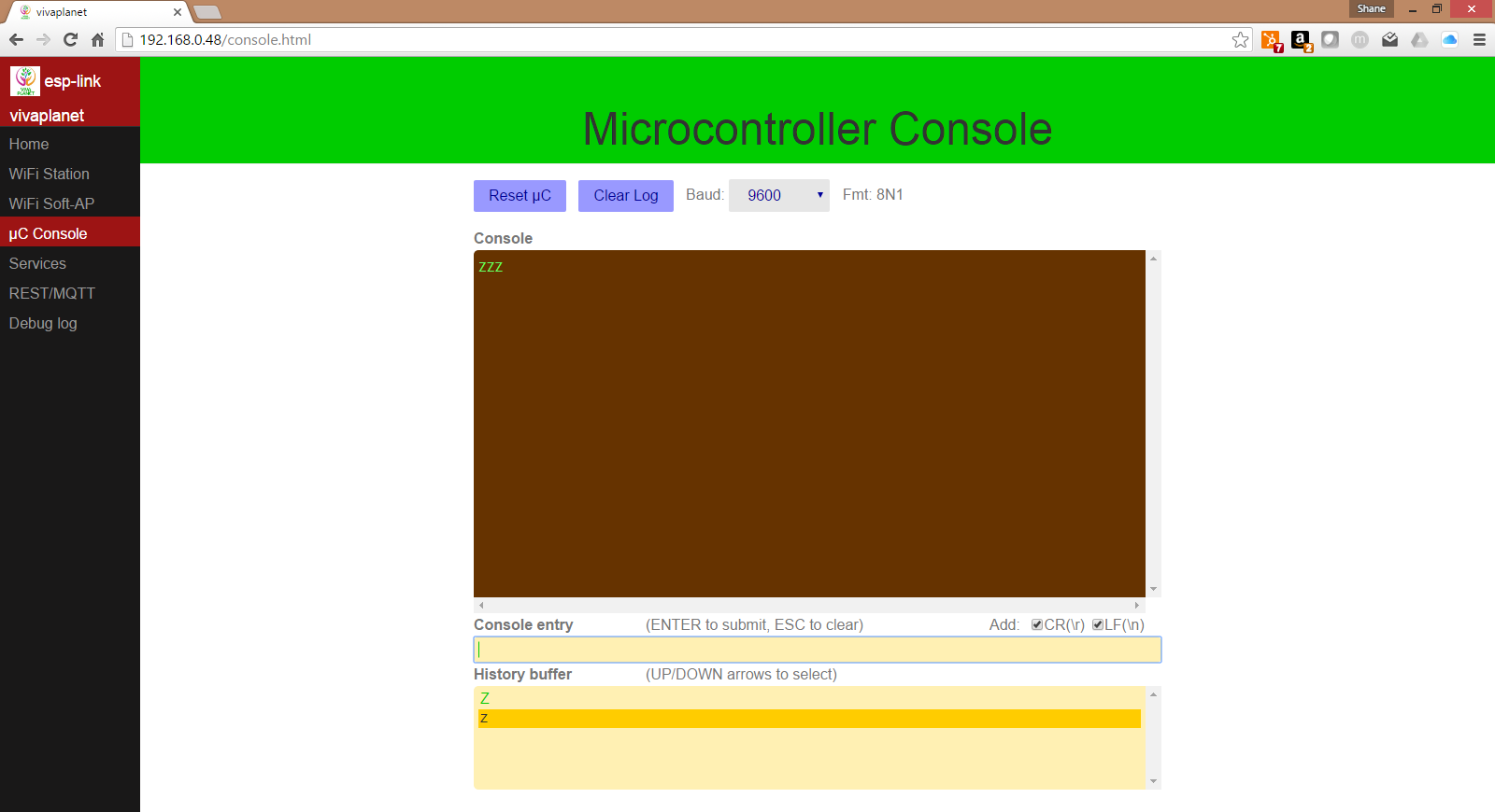
You should have your ESP and STM32 wired as shown at the top of this page. If it is and you've used the code shown above you can send the Z character back and forth! I know you've always dreamed of sending Z's over wifi and now you can...
Here is what it looks like on the ESP Micro-controller console.
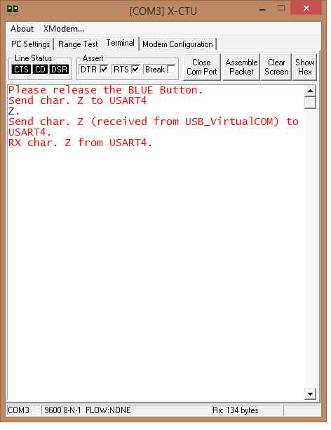
 Here is what it looks like on the PC from a terminal (I used X-CTU but really anything like putty, teraterm or hyperterminal would work).
The next embedded systems post is going to be a little more complicated. We are going to (attempt) to address programming the STM32 with the ESP-Link. They don't currently have this functionality but why not add it? :-)
Discussions
Become a Hackaday.io Member
Create an account to leave a comment. Already have an account? Log In.
Hi, this feature might pave the way to remote-flashing for STM32, because the bootloader of a STM32 is waiting for 0x7F sent using the setup of "one start bit, 0x7F data bits, even parity bit and one stop bit" to enter into UART mode
https://github.com/jeelabs/esp-link/pull/163
Are you sure? yes | no
Hello, have you made any progress on programming the STM32 via ESP?
Are you sure? yes | no
Not quite yet, we will be sure to have an update when we figure out/implement that feature. Thanks for following the project!
Are you sure? yes | no