 AVR
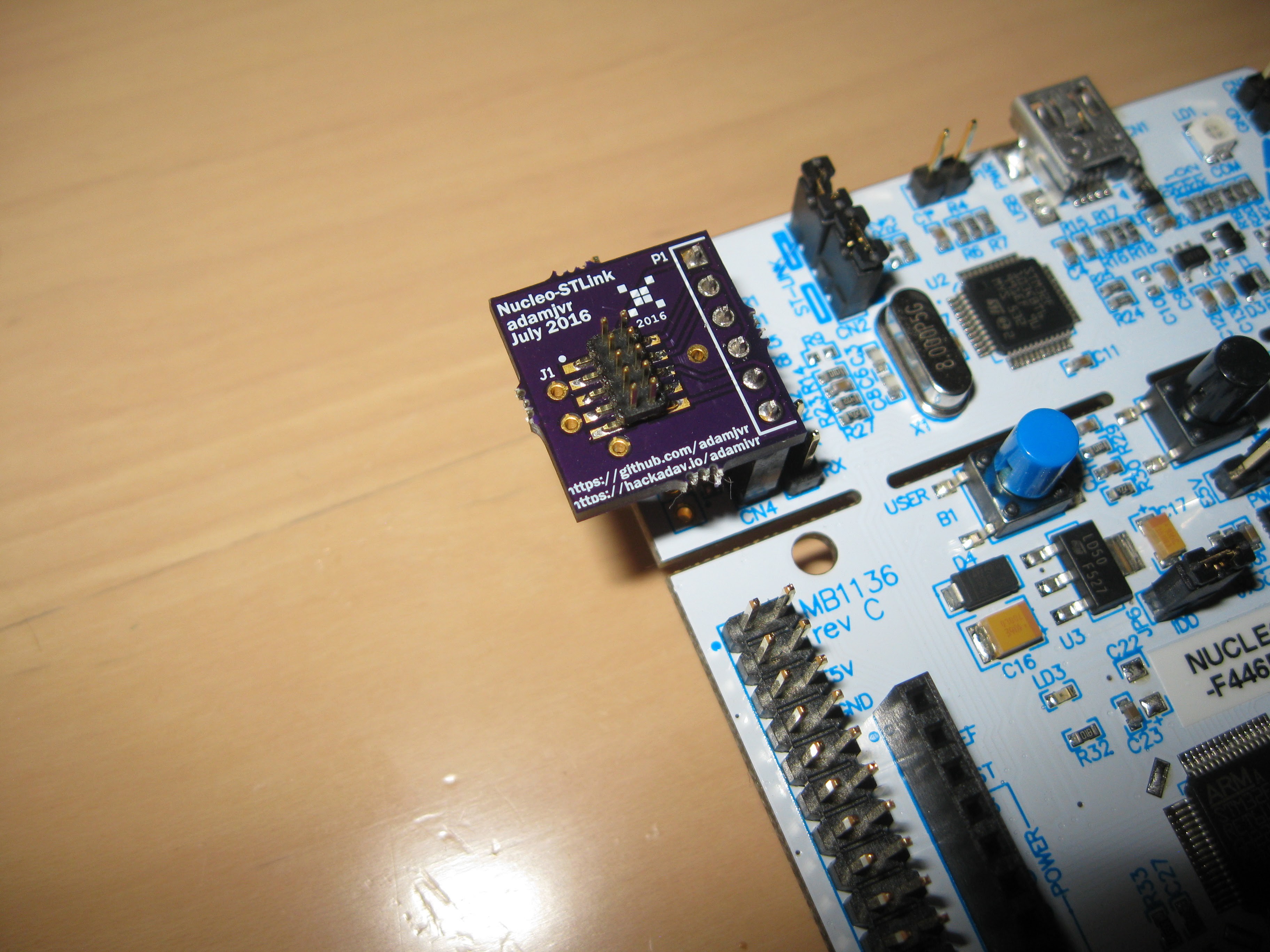
AVRSo its been a while since we talked about the SunLeaf hardware. There has been quite a bit done since the last post. In the last update I showed what I had populated so far on the SunLeaf 0.1a PCB. The populated sections included, USB connector and suppression, STM32 circuitry, sensor muxing circuitry, ESP-02 module, programming headers, and transient suppression circuitry. With all that populated the SunLeaf was ready for testing but I realized that I didn't have a way to connect the ST Nucleo board to the SunLeaf to program it.
My solution was to make a small adapter PCB that lets you hook up the STLinkV2 integrated into the ST Nucleo board to any target board over the ARM Cortex M debug port (10 pin 1.27mm pitch header ). The adapter took 10 days to make at OSHPark which delayed testing. After assembly I was able to put it on my ST Nucleo, pull the jumpers and presto STLinkV2 for cheap:
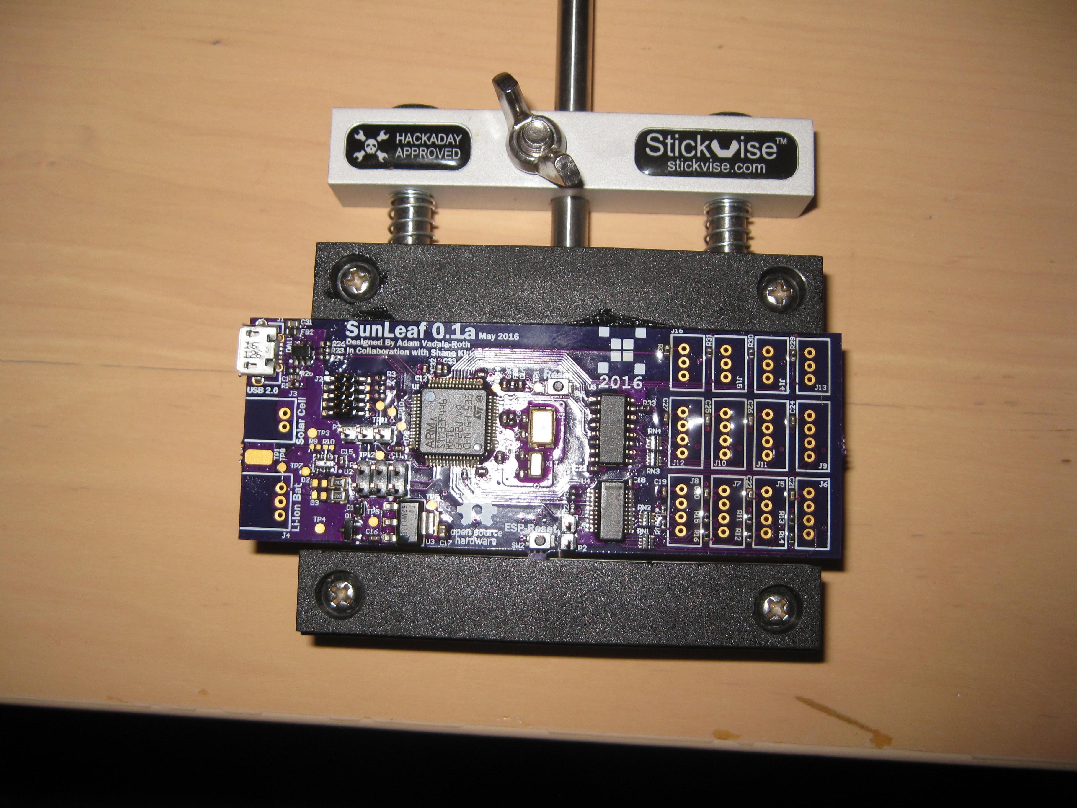
Moving on, last update I mentioned that the footprint to the solar battery charge controller IC was flipped making it not possible to populate and function. Well I made a mistake in my analysis turns out that the footprint was just fine, I only labeled pin 10 as pin 1 with the dot marker on the PCB which made me think I got it wrong during assembly. So I decided to populate the remainder of the PCB and start testing it. The fully assembled SunLeaf 0.1a :
So with the fully populated SunLeaf I started testing things down at the basics. First I tested power, I plugged it in via USB, and checked it with a volt meter. The MOSFET for switching from battery to USB power for feeding the 3V3 regulator worked successfully. The LDO was also pumping out the correct 3.3V as expected.
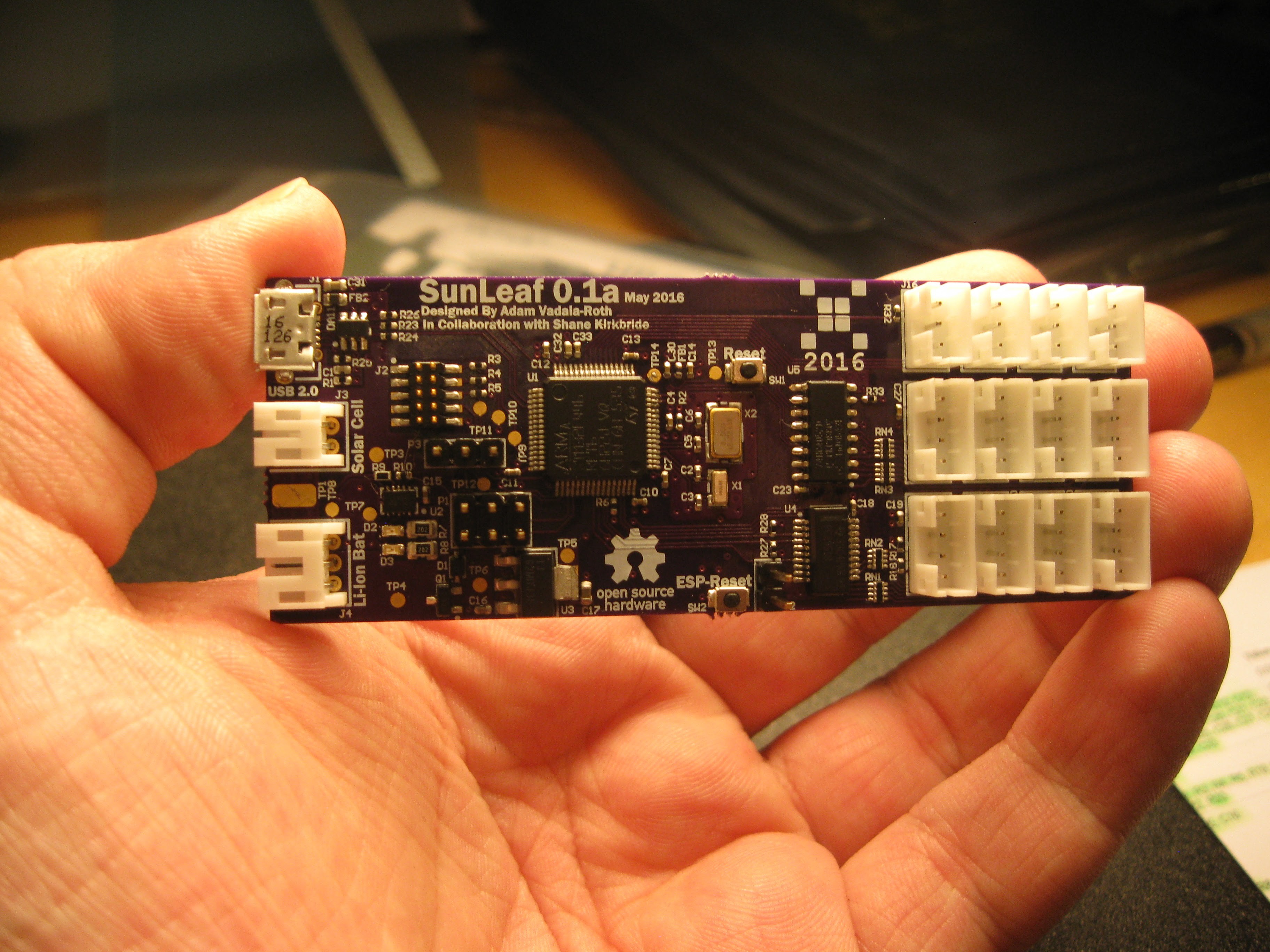
Next I decided to test programmability of the two systems on board the SunLeaf. The SunLeaf is effectively a dual processor board with the STM32F446RET6 and the ESP8266 (ESP-02 Module) linked over UART serial. Their link is jumperable on this revision, so the ESP8266 can be programmed over its UART port. So to begin I wired up the ES8266 to my Adafruit FT232H breakout, wired up the SunLeaf to the Nucleo :

Next off was to test the STM32F446RET6, the main processor. ST Microelectronics makes this sort of stuff incredibly easy. They have a awesome STLink utility program that lets you flash code, verify, and do lots of testing stuff with your STM32 target projects. You can find it here if you want: http://www.st.com/content/st_com/en/products/embedded-software/development-tool-software/stsw-link004.html . So with the Nucleo hooked to the SunLeaf I used the utility's connect to target function and it successfully connected. So the STM32 started up fine, indicating that the reference design with my adjustments worked out ok. Next I wanted to test the serial, so I wrote a simple program in mBed to just print back whatever is typed into the PuTTY terminal, I also wrote a shrot program that just looped and printed back. Next test was to test the UART muxing , this was tested with a simple mbed program to just toggle IO to select channels and output PWM signals, I used my oscillscope to test the UART sensor ports. I also had some crosstalk issues on the UART muxing lines to the ports, I suspect solder bridging with the network resistors or crosstalk, I'm thinking about omitting thos resistor networks in rev 2 but I need to do more digging on the problem.I2C and the solar section still need to be tested, I am waiting on parts and a trip to Microcenter to complete testing.
Another smaller update is that the ST-Client software that runs on the STM32F446RET6 is now available on our github as a ARM GNU Toolchain project. Currently built successfully under Debian stretch, any POSIX style system should suffice. Here is the repo: https://github.com/HydroPWNics/SunLeaf-STM32 you can get the ARM GNU Toolchain here: https://launchpad.net/gcc-arm-embedded . Eventually we will have a combined repository that compiles and builds code for both the ST and ESP together. This is just a start of moving towards an entirely make syntax buildable project.
So In Summary:
1. The STM32F446RET6 programs and talks to the programmer (ST Nucleo + my adapter)
2. UART peripherals on the ST are functional, tested by printing back to a com port via FTDI board
3. Control UART multiplexer with GPIO
4. ESP8266 as setup is not responding to a programming routine
5. I got the mbed project for STM-Client building with the ARM GNU Toolchain under debian
6. USB power switching works, I can run the board off bus power just fine, the VBUS signal successfully drives the MOSFET switching from solar panel to VBUS to the regulator and charging circuit
Moving forward a new version of the SunLealf PCB is being worked on right now, development has been switched to KiCAD, the next post on hardware will be covering that. While developing the new PCB, solar battery charging and I2C function and muxing will be tested and any other issues will be mitigated in the 2nd revision of the PCB. Stay tuned for more hardware fun !!!!
Discussions
Become a Hackaday.io Member
Create an account to leave a comment. Already have an account? Log In.