 AVR
AVROver the last week or so, the SunLeaf has grown from general specifications to a full fleshed out hardware design. Most of the work went into choosing components and designing the schematic for the printed circuit board that will be the SunLeaf
module. Concrete Specifications:
- ST Microelectronics STM32 STM32F446RET6 ARM Cortex M4F 168MHZ Microcontroller
- ESP8266 WiFi System on a Chip, ESP-02 Module (no antenna w/Connector)
- 8x UART/USART Seeedstudio Grove Sensor Ports
- 8x I2C Seeedstudio Grove Sensor Ports
- Texas Instruments BQ24210DQCT Solar/USB Lithium Ion battery charge controller
- USB 2.0 Configuration and Updating
- ESD Protection on all connectors
- Over the air updates over WiFi
Below is a functional diagram of SunLeaf that shows how al those specs come together:
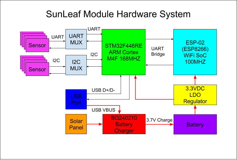
Overall SunLeaf is pretty simple, the system is controlled by the STM32F446RET6 running a simple baremetal firmware. Network communications and server interfacing are handled by the ESP8266 on the ESP-02 module. All the sensors connect via SeeedStudio Grove connectors, they are interfaced/sampled by the STM32, the sensors talk over either I2C or UART. In order to interface with many of these sensors without wasting UART/I2C peripherals (STM32 chip has a few of each) muxing circuitry will be implemented to handle 4 sensors per peripheral.
The more interesting part of SunLeaf is its power system. The onboard power supply charges a lithium polymer battery from either a solar cell or USB via the Ti BQ24210DQCTchip . USB charging automatically disables the solar panel when connected to protect the charge controller (BQ24210DQCT). For board level power a simple low dropout 3.3V voltage regulator drops the battery voltage down from 3.7V, this regulator feeds all logic devices on the board. The battery is a single cell lithium ion battery with integrated thermistor. The type with thermistor is used because the BQ24210DQCT monitors battery heat for safe charging without fire.
Moving on we have the schematic for SunLeaf just about complete, only say “just about” because schematics can change over the course of the board design process. Just to note, a lot more goes into a schematic than placing the relevant symbols and connecting them into a circuit. When designing a printed circuit board it is important to keep manufacturing mind at all times, its jsut as important as the electrical theory. Traditionally a schematic is only a method of representing a circuit, for printed circuit boards that schematic has to represent much more than just the circuit. In PCB design the schematic is not only a model of the circuit but contains all the component information, a list of nets (electrical connections), and component footprint data.
When creating a schematic for a piece of hardware components need to chosen for availability, cost and function this is called design for manufacture. A lot of folks just design something and make it, this works for one off designs but not in the case of mass production, right out of the gate SunLeaf is a design for manufacture type project. Over the course of making this schematic all the components were researched and carefully selected. Things to consider when finding components are the quantity/price (get the best price on parts), quality, availability, and electrical qualities. The trick is to find parts that satisfy all these marks and to choose them all during the schematic phase before the board is even started. Having complete schematic and a set bill of materials makes designing the actual board a lot easier.
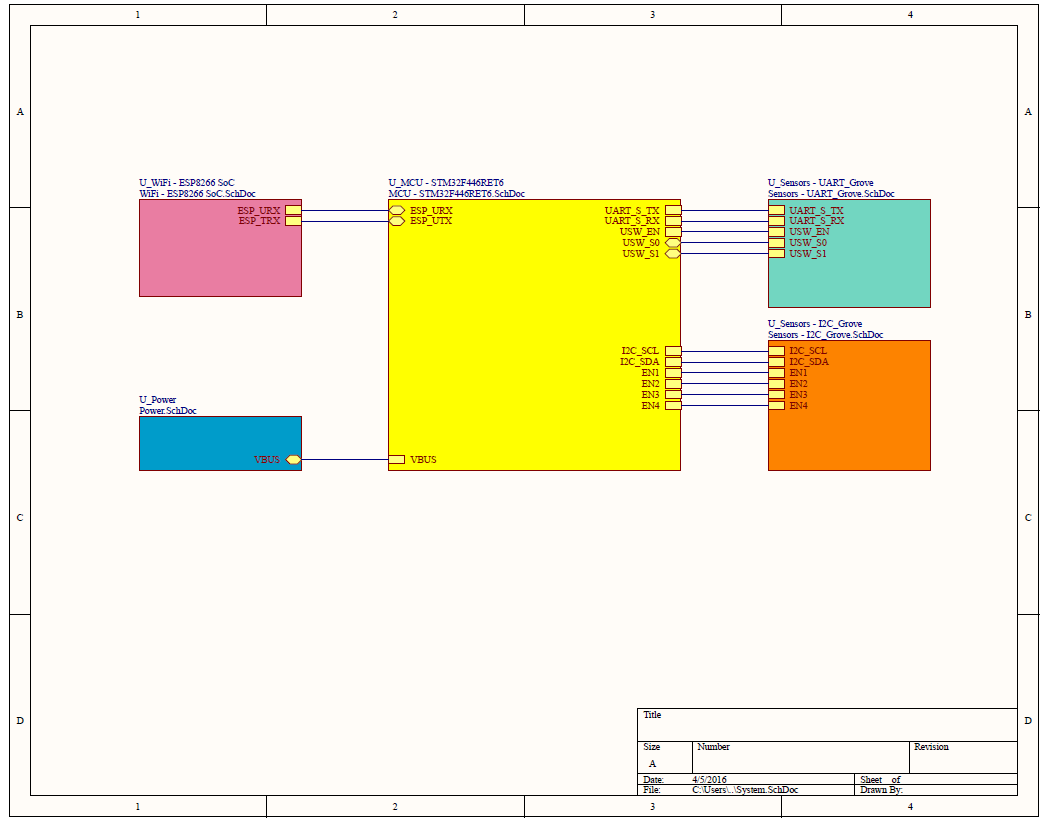
All that being said here is the schematic after a lot of work vetting components and sculpting of the schematic itself:
Schematic System Overview:
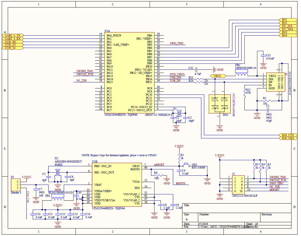
STM32F446RET6 Microcontroller Schematic
WiFi System On a Chip
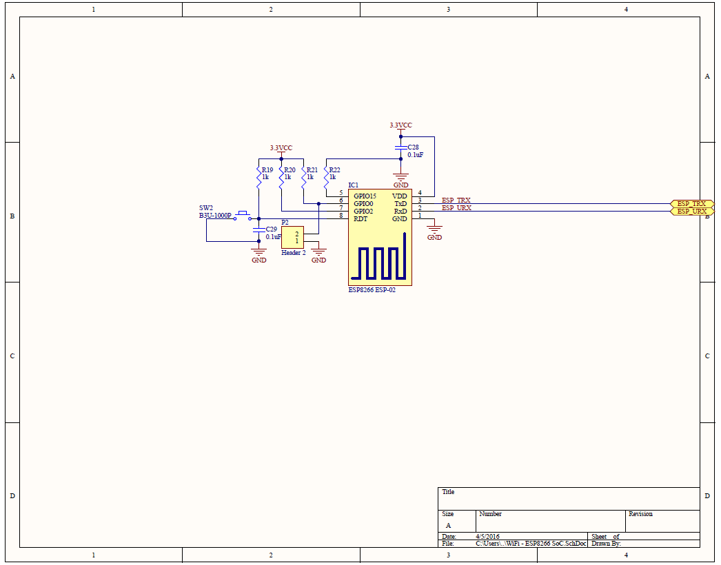 On this page there is the wifi system on a chip. The module is an ESP-02 module, it contains an ESP8266, flash boot, supporting components, and an antenna connector. All included are supporting components for stable operations, a dedicated reset button and a jumper for flashing firmware.
UART Grove Sensor Ports
 This sheet contains the UART Grove ports on the SunLeaf. Each connector is ESD protected with a TVS diode array, the muxing is handled by a 74HC4052 analog multiplexer demultiplexer. Each connectors has a resistor array inline for noise reduction and impedance matching.
I2C Grove Sensor Ports

System Power Supply and Battery Charging
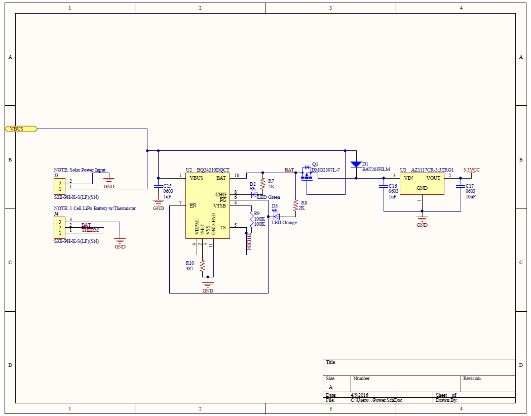 On the last sheet lives the power system for the SunLeaf. The BQ24210DQCT charge controller IC, this is wired to the solar panel input and USB input, the LDO is fed from the battery charged by the BQ24210DQCT. When a USB cable is connected a MOSFET and diode switch the LDO’s power input from the battery to the VBUS signal for USB charging during configuration or firmware flashing.
So that’s that well that’s the schematic! Now with a solid schematic SunLeaf is on its way to becoming a piece of physical hardware. The next update we have will be on software architecture and development, and not so long after we should have a PCB to show.
Stay tuned for more, happy hacking !!!!!!!!!!!!!!!!!!!!!!!!!!!!!
Discussions
Become a Hackaday.io Member
Create an account to leave a comment. Already have an account? Log In.