 R. Scott Coppersmith
Hardware – Instrument Transmitter
The ultrasonic anemometer is powered by an external DC power supply from 12 to 30 volts.The Bluetooth interface requires a 5VDC power supply.A circuit board was built with a 5VDC regulator to utilize the same power supply as the anemometer.Two other circuits are required on the instrument side, a RS232 voltage level shifter, and the Bluetooth RF module.Bluetooth modules have different output levels for specific applications, a Class-1 module was chosen for this project for maximum distance (20m-30m).The circuit board for the instrument transmitter is shown in figure 1.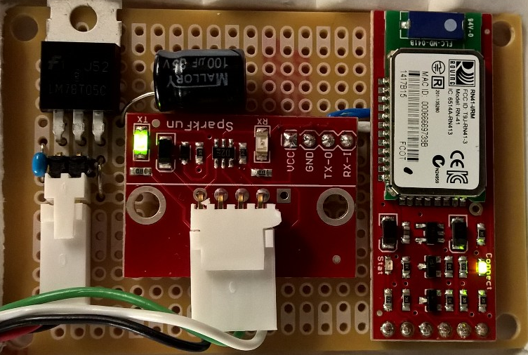
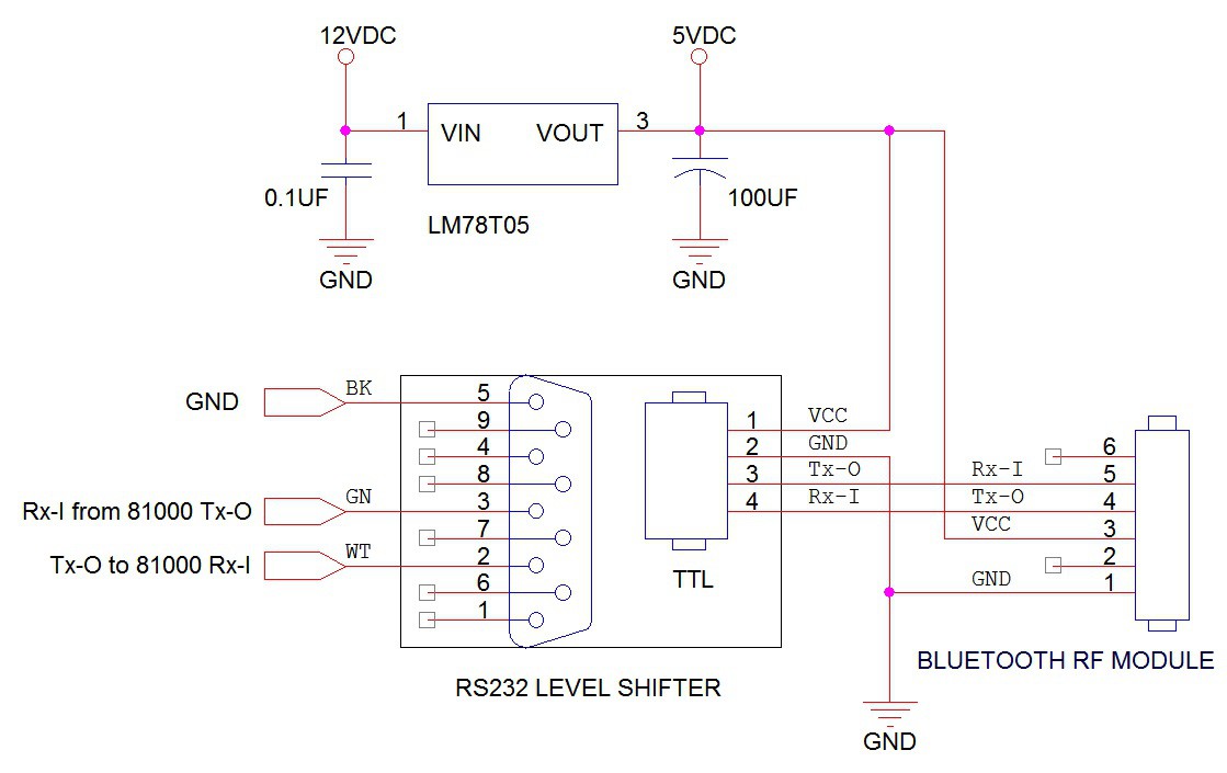
The Bluetooth module was designed by SparkFun electronics (WRL-12580) as a simple streaming modem, and is capable of baud rates up to 115200bps. The inputs to the module are TTL Rx, Tx, and 3.3 to 6 VDC.The module can be programmed for master or slave operation, and can be bound to a specific module, or can pair to the first device it finds.The RS232 level shifter for this project is also from SparkFun electronics (PRT-08780) and interfaces the Bluetooth module TTL Rx and Tx pins to the RS232 level pins of the instrument.The schematic for the instrument side wiring is shown in figure 2.
Hardware – Bluetooth DataLogger
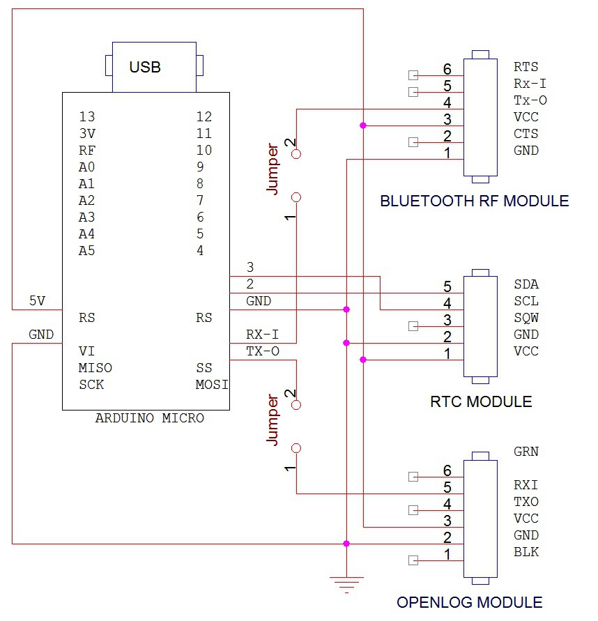
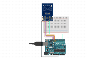
The datalogger circuit was built by combining four off-the-shelf modules.The first is an Arduino ® Micro prototyping board designed around the Atmel ATmega32u416MHz processor.A real-time clock (RTC) module from SparkFun (BOB-12708) is connected to the Arduino via a two wire I²C interface. This module is required to add a timestamp to the data stream.The data is received by another Bluetooth module (WRL-12580) and the combined time information and anemometer data is written to a micro-SD memory card using another SparkFun product called OpenLog (DEV-09530).OpenLog is a small PCB that combines a SD card reader with an AtmelATmega328 processor,and uses an open source software library available through the GitHub repository.The datalogger is programmable using the Arduino ® PC software, and the PCB can be powered by battery or a small (500ma) 5 VDC power supply.The datalogger is shown in figure 4.

The four modules are connected using a standard prototyping pcb and a few jumpers to allow in-circuit programming of the Bluetooth module and the OpenLog module with a serial port TTL adapter and a standard PC terminal program such as Hyperterminal or TeraTerm.Figure 5 shows a block schematic of the module wiring.The 5 VDC power to all the modules comes from the micro-USB connector on the Arduino board.An externalpower supply can power the datalogger from this port also.
Software – Bluetooth Module Programming
To save time and keep the Arduino program simple, the programming for the modules are done off-line before powering the system.The parameters for the Bluetooth module are as follows:
***Settings***
BTA=00066669aaaa
BTName=RNBT-aaaa
Baudrt=38.4
Mode=Pair
Authen=0
PinCod=1234
Bonded=1
Rem=00066669bbbb
In this mode, the Bluetooth module will automatically look for device 00066669bbbb and pair with it after powering up.
Software – RTC Module Programming
The real time clock module only needs to be set once when the lithium coin cell battery is first inserted.A line in the Arduino code is added to set the clock, then it is commented out and reloaded.The following is the line of code required to adjust the time to 17 April 2015 at 11:20am:
Rtc.adjust(DateTime(2015, 4, 17, 11, 20, 0));
The RTC module keeps time in seconds only, so the Arduino software must add the milliseconds to the timestamp before sending the data to the SD card.
Software – OpenLog Module Programming
The software for the OpenLog module did not need to be changed for this project.The configuration settings are written to a file on the SD card when a new formatted card is inserted in its socket.The...
Read more »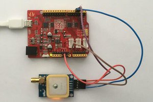
 hIOTron
 Sagar 001
With Gizmogo, sellers can navigate the online marketplace with confidence, knowing they are in capable hands and poised to receive exemplary service and value for their devices. https://www.gizmogo.com/sell-laptops