0%
0%
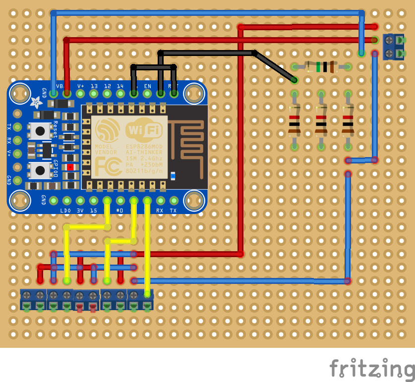
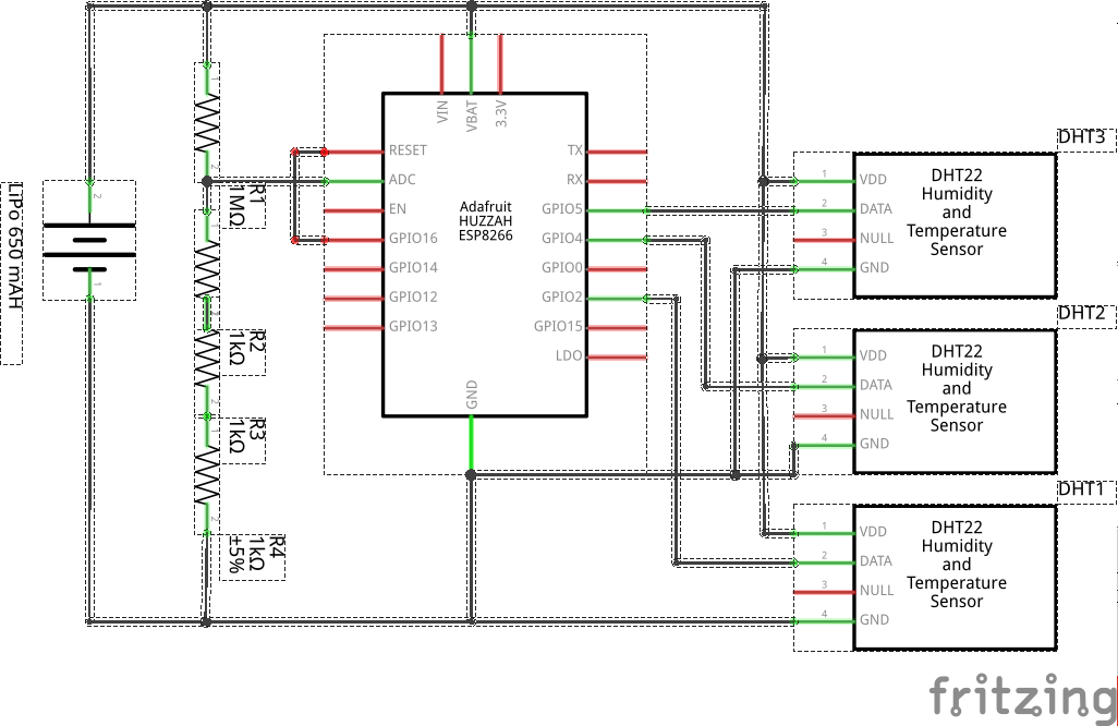
Beehive Monitoring, Now With WiFi
Using a WeMos ESP8266 D1 Mini and DHT22 Shield to monitor beehive temperature and humidity
 Don R-Crenshaw
Become a Hackaday.io member
Already have an account? Log in.
Just one more thing
To make the experience fit your profile, pick a username and tell us what interests you.
Pick an awesome username
hackaday.io/
Your profile's URL: hackaday.io/username. Max 25 alphanumeric characters.
Pick a few interests
Projects that share your interests
People that share your interests
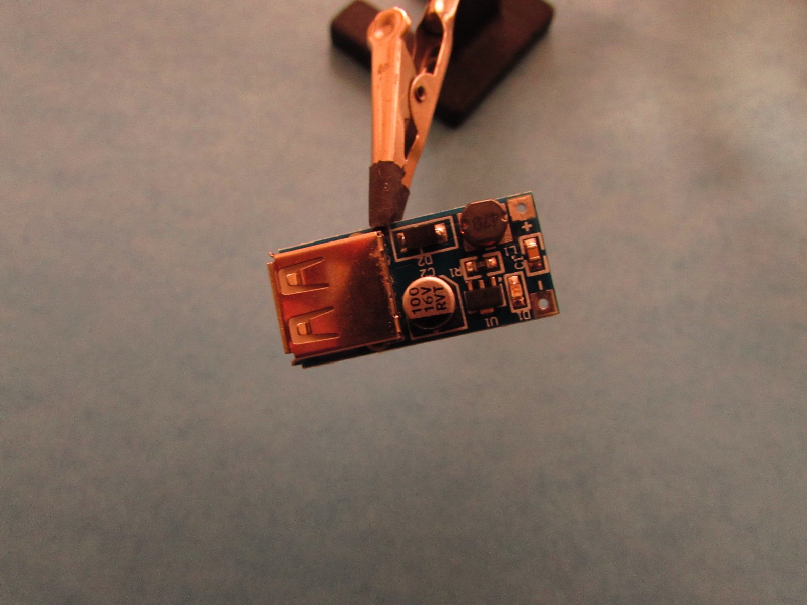 A happy little fellow with a great big USB connector.
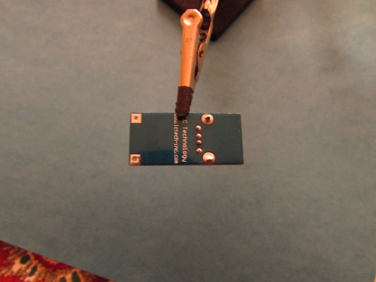 It's the top and bottom pins of that row of four I want to expose.
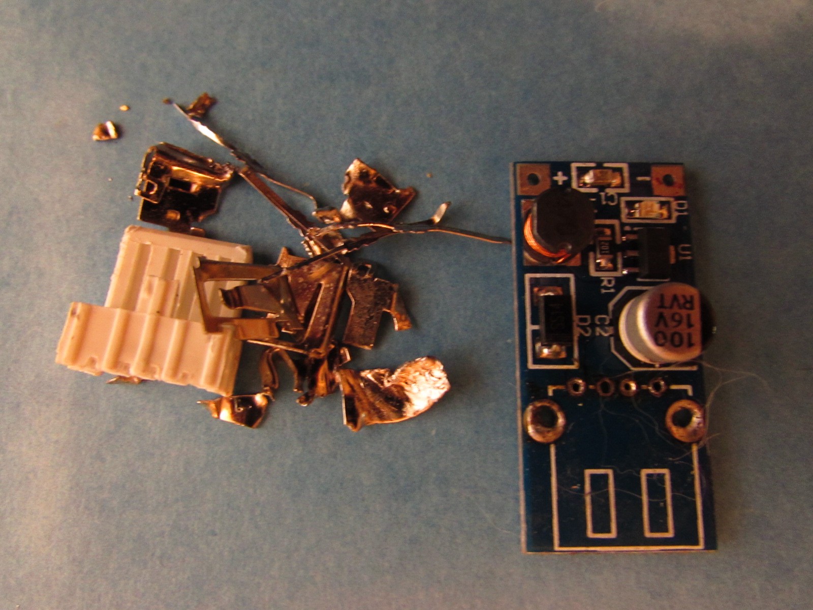
 It's the top chunk of perf board in this picture, connected to the LiPo and ready to be stuffed into its weatherproof enclosure /sandwich box and connected to the solar panel.
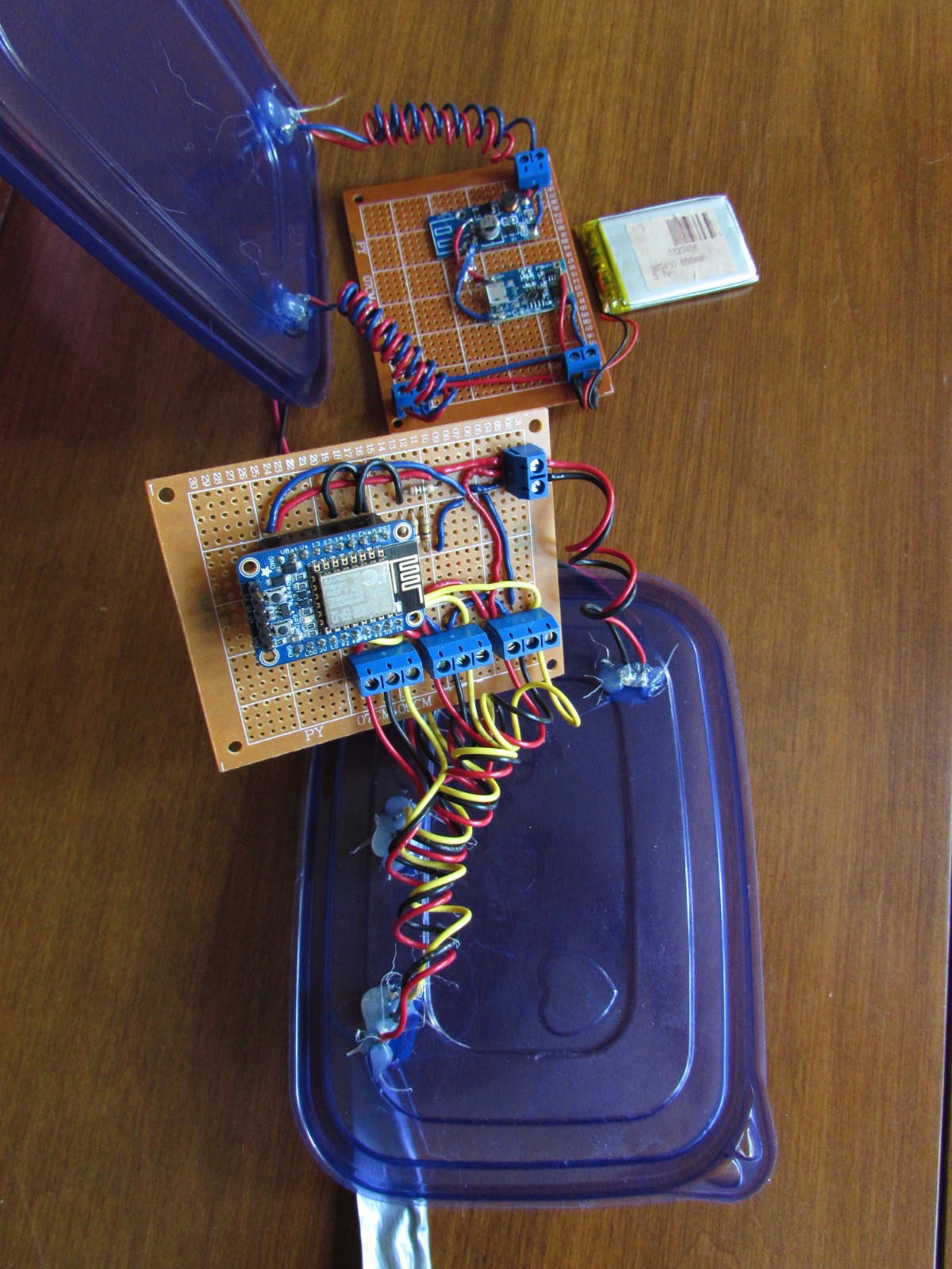
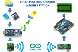
 Open Green Energy
 MCenderdragon
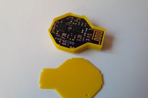
 Max.K
Max.K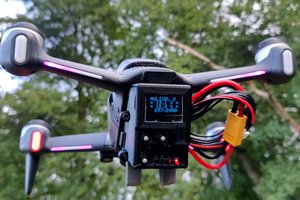
 AirCruiser