 k
kDesign considerations
The pm2.5/pm10 sensor
Of course we can't easily make pm2.5/pm10 sensor ourselves but fortunately there are some existing ones on the market. We are looking for a sensor that is easy to buy and reasonably cheap but its measurements can actually be trust. Here's the list of sensors that were considered:
- Samyong DSM501 / Shinyei PPD42NS ( ~4-5 USD)
- Plantower PMS1003/PMS3003 (~17 USD)
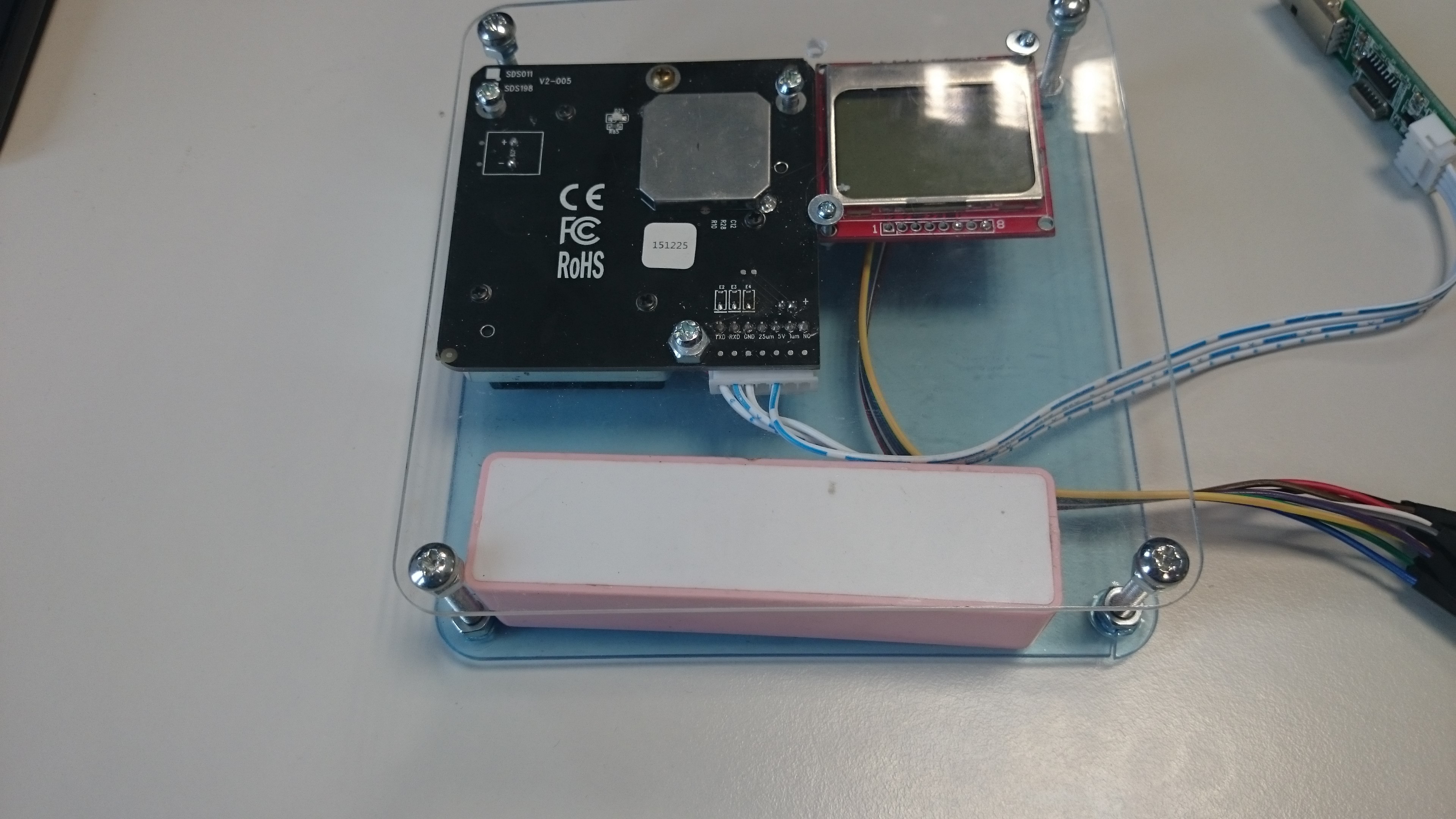
- Novafitness SDS011 (~23 USD)
I didn't want to buy all of them so I had to choose one. Based on few Internet reviews, from which http://aqicn.org/sensor/ is the most convincing, I've chosen the last one for following reasons:
- The price is still reasonable
- It definitely has the best reviews on the Internet, even though it's not as popular as cheaper ones
- The communication is done using UART, with both automatic sensing and on demand sensing. It also supports sleep mode (but this could be easily simulated by cutting of power to the device).
I bought it and first tests show quite good correlation between results obtained and expected.
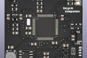
Microcontroller
I would like make this project work on two platforms - normal atmega328p based Arduino (if uploading is not needed and reading current values from LCD is good enough) and ESP8266 for full featured version. In both cases, Arduino environment will be used for programming as this not only makes prototyping easy but also makes it much easier for others to contribute to the project.
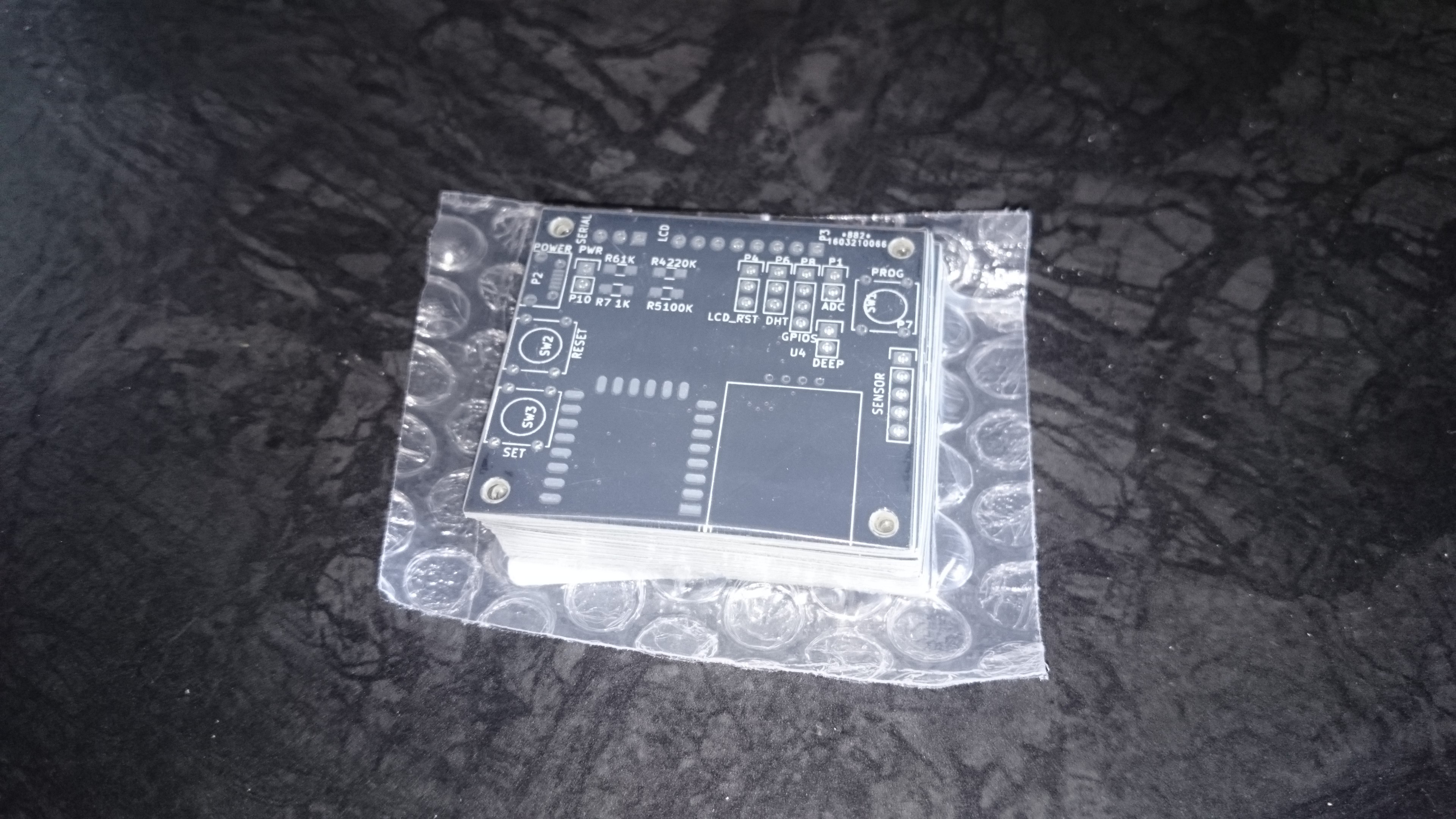
ESP8266 comes in many surface mountable models. ESP-12F seems
to be the best of them as it has all the usable pins broken on the
edge. ESP-07 has mostly the same footprint (short of flash pins which
probably won't be used in this project) but also has connector for
external antenna so I would like the main board to also be compatible
with this one.
Power source
The main power source should be A/C power as I hope those modules to run 24h a day, reporting all the measurements for further analysis. All the sensors uses fan for air ventilation using quite a lot of power so lasting on battery for weeks is not really possible. Still, I would like it to be portable enough to take it with me and do some measurements outside. At the same time I want to be cheap.
The sensor (sds011) requires 5V (with 3.3V UART). While Arduino can run on both 3.3V and 5V, ESP8266 is 3.3V only. So we need 5V and a voltage regulator.
For those reasons, microusb will be used for providing power. Cheap 1117 linear regulator will be used for 3.3V (at least in first revisions) to ESP8266. Microusb connector makes it easy for everyone to find spare power adapter and also makes it very easy (and cheap) to use battery by using cheap power banks.
SDS011 module takes ~100 mA when in active mode and around 3mA when sleeping. ESP8266 requires ~100mA when uploading data, ~70mA when idling with WiFi connected, ~15mA when WiFi is disabled (so called modem sleep) and <1mA when in deep sleep.
LCD
I would like current values to be displayed somehow. While ultra low power consumption is not a priority right now, I would still like this module to be portable so it has to be usable on batteries with LCD constantly displaying values. Also, since ESP8266 is planned as a main platform, it has to be usable with low amount of pins. And again, it has to be cheap and easy to buy.
Few LCDs were considered:
- standard 16x2 HD44780 based LCD with i2c adapter (~2 USD)
- OLED 0.96" SSD1306 displays (~4-5 USD)
- PCD8544 Nokia LCD (~2 USD)
OLED displays may be operated using both SPI and I2C but they are smallest and most expensive from the three. They also use quite a lot of power (~20mA). HD44780 uses ~2-3 mA and are cheap so they could be used but they have quite limited display area. PCD8544 based displays use least power ~0.2mA, has ~1.5" diagonal and can easily provide 12x6 of very readable text area. They can be driven by only 3 pins which is good enough. Nokia LCD seems to be the best candidate for this project.
Usability
I assume most of the users of this module won't necessarily be programmers,...
Read more »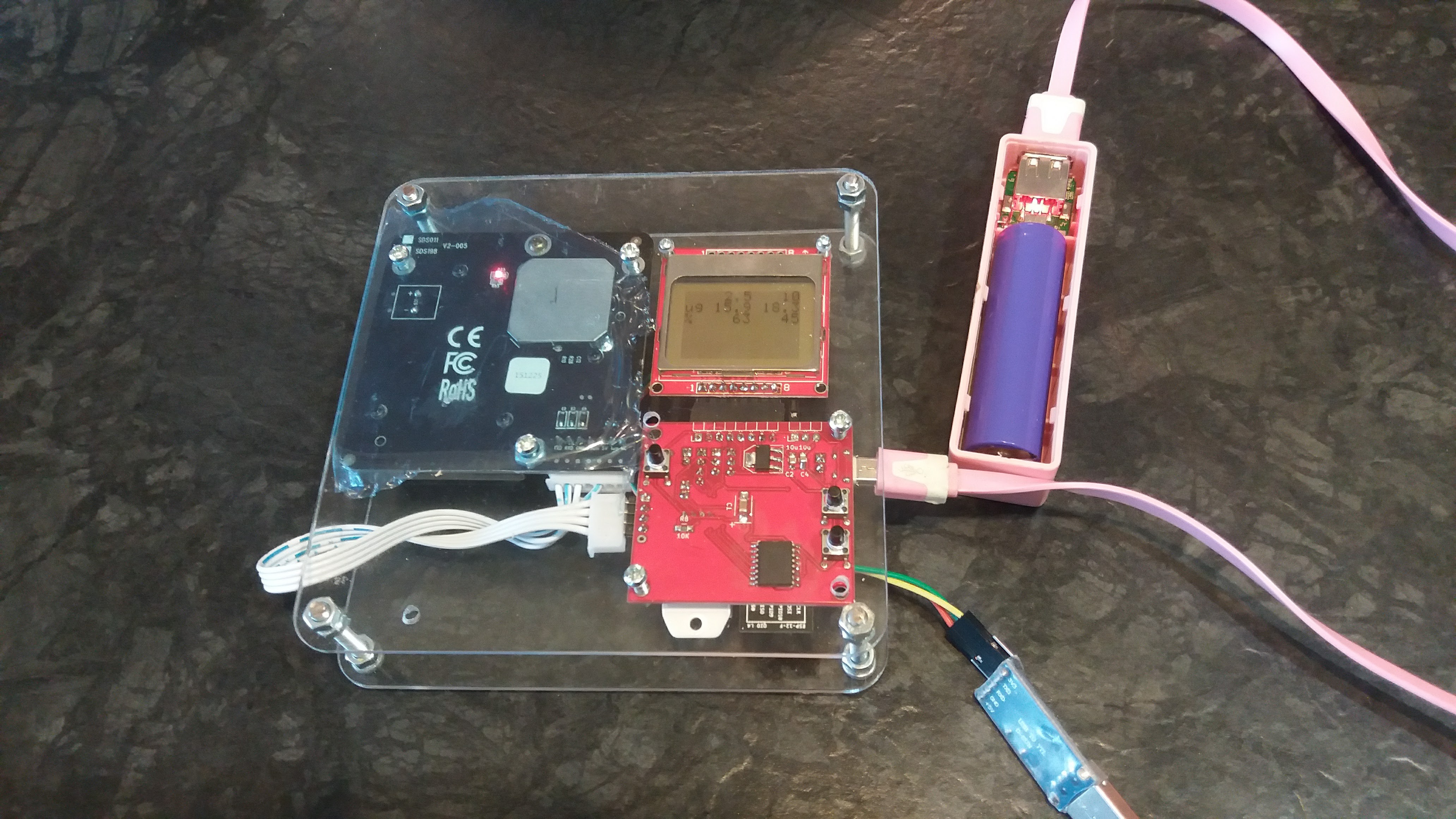

 Matias N.
 pastcompute
 Jeff Taylor
 Audrey Robinel
Hello, i would like to use the sds011 sensor with Arduino mega 2560 and a LCD shield, but unfortunately i didn't find any code.
If you have any idea about how to modify your nice project/code to let it work with Arduino mega and a normal LCD shield, please let me know.
Thanks for any reply.
Cheers.
Stefano