Close
0%
0%

sound-based weather station

Converts weather into microphone-vibrations that DSP on a small computer can resolve into weather data

Similar projects worth following
Aims to re-imagine a classical weather sensor down to a single passive structure with no moving parts. The structure being designed is able to modulate rain, directional wind speed, and temperature into arbitrary, but uniquely identifyable vibrations. Vibrations are sensed by a microphone, with output digitised and processed by a computer to un-map the weather modulations back into incident preceived weather.

The Problem being solved:

Monitoring weather is becoming more important as climate change bears upon us. Accurately observing microclimates, or specific areas or events in detail is complex & costly. This is because Weather stations typically contain moving parts that can degrade over time, and are relatively complex to deploy. Ones that use sound-based measurement are usually expensive, delicate and require customised wired data interfaces. This limits stations to (semi-) permanent installations, with dedicated computers. There are currently no cheap, small accurate stations that can be deployed either cheaply , simply or rapidly.

KEY POINTS of how this project solves the problem:

1. Reliable - The device has no moving parts.
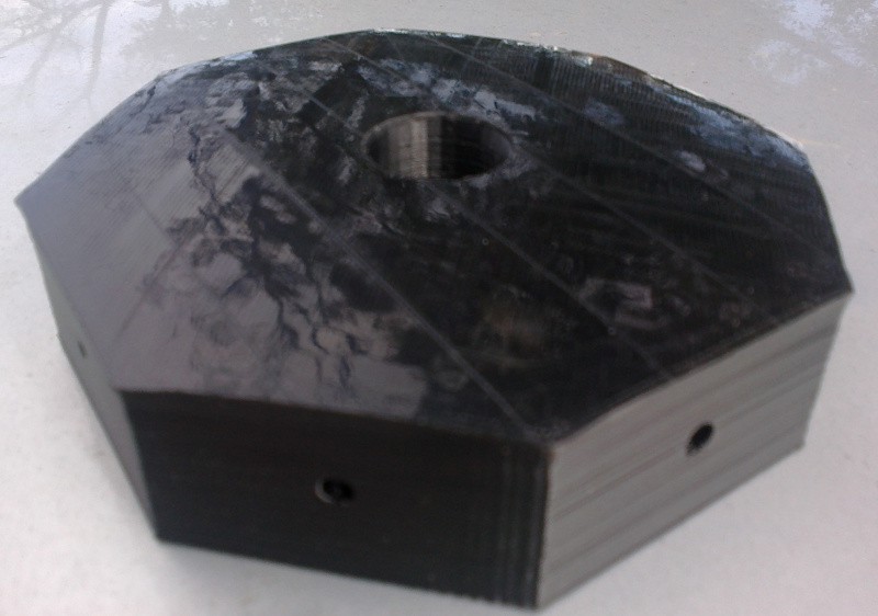
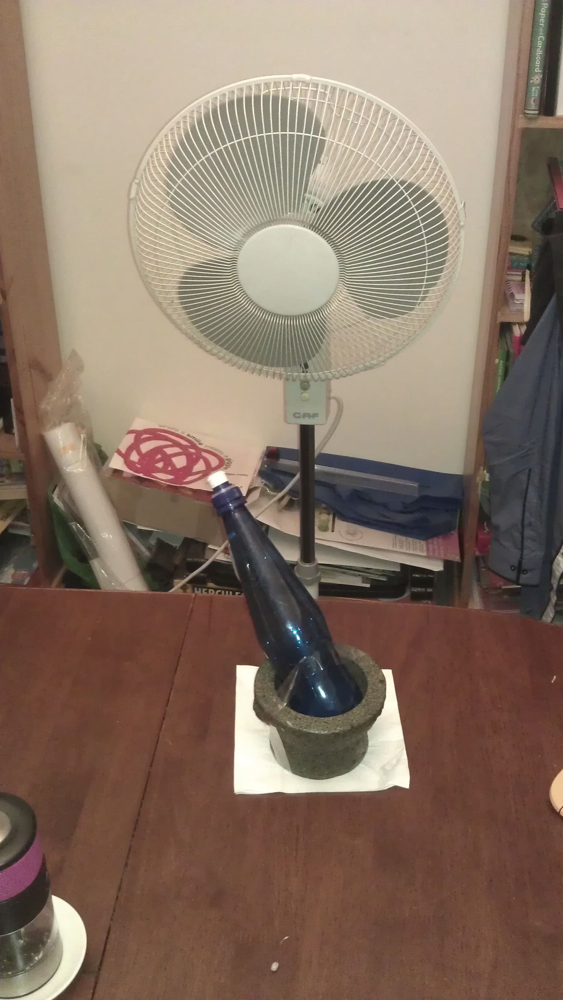
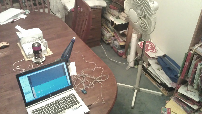
2. Cheap - Using a 3D-printable plastic structure with a simple digitising computing device ( eg smart-phone or Raspberry-Pi with USB-sound + mic)
3. Repeatable & Calibratable: 3-D printed structure means accurate copies for identical swap-in/out.
4. Expected Accuracy: Medium (partly Processor-dependant). This station will probably not replace permanent, high quality stations.

5. Simple: Its nothing more than a small lump of uniquely-shaped plastic ( + some smart-device). It can therefore be 3-D printed in large numbers and deployed in much greater numbers than classical stations. Much of the complexity has been moved into the software domain.


Potential Use-Cases:

  • small , quick and easy to deploy in numerous locations during emergency events: EG Monitoring micro-climate during Rural Fires .
  • Study of detailed climate spatial-variations over a particular area ( EG deploy 10 or more)
  • Remote locations where very-low power, temporary monitoring / reporting is required.
    • EG: Farms during harvesting or other climate-critical occasions
    • Beach / Surf forecasting in remote coastal locations.

How it works:

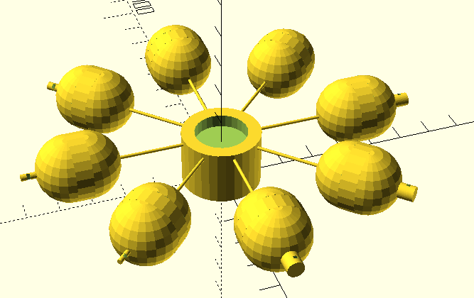
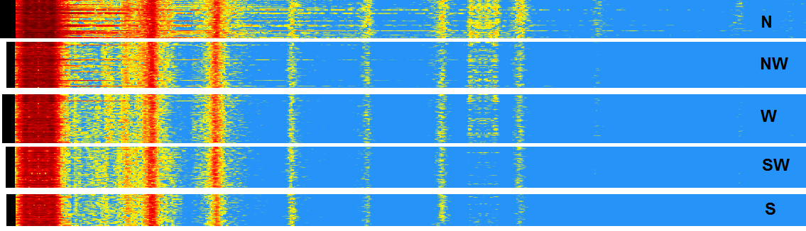
Since weather is fundamentally a physical phenomenon, it can be modulated into other physical representations. In this project, we use the medium of sound ( IE resonant vibrations of molecules) to initially understand the direction and speed of wind, as well as temperature and rainfall. Air pressure and humidity are also theoretically possible, but will be harder to implement.

GITHUB for OpenSCAD design: https://github.com/pastcompute/HackadayPrize2016

The model is released under creative commons license.

See project log for our plan.

  • Plans change

    pastcompute05/22/2016 at 11:15 0 comments

    So due to various commitments for both of us, we haven't had a lot of spare time for this recently.

    So now we will push on and enter the Citizen scientist category of the Hackaday Prize 2016.

  • The next step / planning

    pastcompute04/25/2016 at 00:21 0 comments

    The plan going forward is to do controlled testing of the 3D printed models.

    Dave will be starting testing with the model I already made, which we expect to give us some level of directionality. However the model I created has a couple of issues, including that the major cavities are all the same size with the inlets size varied to vary the resonance. We think though that it would be more sensible to vary the major cavity sizes and keep the inlet sizes the same as the cavity will be the dominating factor. Which is going to be a more tedious but interesting challenge in OpenSCAD that I will be tackling through the next stage Anything Goes.

    We then intend to develop software that takes recorded sound from the central void and performs the direction / speed processing analysis.

    Plans are of course malleable, but our first guess based on our time available is:

    (a) now+1 Month - refine 3D printed models and test the math - fits well in Anything Goes stage. So during this stage skills required include understanding the maths and signal processing, and design & creation of 3D printed models

    (b) now+3 Months - code software and then go out and test it using either a laptop or smartphone and refined model and latest 3D printed sensor. We think collecting the data then fits nicely into the 'Citizen Science' stage. Skills include software development - ideally for a smartphone but given the time constraints we might decide to just go with a program on a laptop, we will play this by ear. And the ability to record and concisely document our results.

    My 3D printer is a home brew based on the q3d TwoUp and has been experiencing a few reliability issues, so an upgrade would not go astray ;-)

  • First physical prototype created

    pastcompute04/09/2016 at 11:29 0 comments

    Armed with @Dave Merrett's inspiration I fired up OpenSCAD and created a first -guess model that could be 3D printed. At present this an octagon with eight cavities.

    The purpose of this first prototype is two-fold:

    • exercise OpenSCAD and the 3D printing process for our desired shape of object, and provide a center of attention for discussion. Having something in your hands is a great prompt for a brainstorming session
    • actually test it with our measurement scenario

    I started out using Helmholtz' law and naively created spherical ended cavities and varied the area of the inlets to change the resonant frequency of each cavity. It is likely that those decisions are actually incorrect, and I should instead have adjusted the cavity volume itself, as the cavity is the primary resonant structure. On reflection we the cavity should have a perpendicular cylindrical end rather than semi-spherical. Further experimentation will certainly help.

    This first prototype was printed using ABS. This was also a mistake, because the 3D printers we have access to need a lot of coaxing to print anything large in ABS, and in this case, the prototype has warped, although it is intact enough to be able to start characterisation with. Being able to print in ABS is probably essential eventually for improving outside use robustness, but we need to get the concept proven first, so the next several prototypes will be printed using good-old PLA.

  • Multi-channel

    Dave Merrett04/07/2016 at 10:26 0 comments

    Now we're going to get into the complex details. For a given number of resonators, they need to be arranged to make it easy for the sound signal processor to differentiate wind speed, direction and temperature. It makes sense to use an equally-azimuthally-spaced set of resonators. In other words, make it just as hard to sense wind from one direction as compared to any other. If we assume the resonators respond to wind-excitation in a classical cardiod-like pattern, we can expect the response from each ( colour-identified) channel as per image below. This is a hyopthetical 3-channel system I simulated using MATLAB..

    Based on this angular response, we can simulate what the frequency spectrum output from each resonater might look like for a given wind direction. Most resonators will also respond at harmonics of their fundamental frequency ( like in bottle demo below), so Ive added these into the spectrum. Plot below is an example of the response when wind slowly rotates around the sensor

  • Results of demo

    Dave Merrett04/06/2016 at 10:07 0 comments

    With the wind coming from the north, I rotated the bottle anticlockwise from ( initally pointing..) north to south , and took screen shots of the resulting sound spectrum at 45 degree increments. (since the aperture is symmetrical, the results should be identical if rotating clockwise).

    The image below shows horizontal sections of the waterfall spectrum from SDR-sharp in rows starting from North.

    Here's a general screen shot of SDR- Sharp in operation..

    And here's the direction-annotated ( RHS) waterfall-plot sections..

    For comparison, heres what it looks like with fan off..

    As you can see, its dimishing as it rotates away from wind.

    By itself, this isnt much use as a wind direction-measurement device, because its impossible to know west from east, or fast wind from the SW compared to gentle wind from the NW, but the next log will explain how more cavities can resolve the ambiguities.

    I made a video of the whole thing that shows whats going on.

  • Demo of the physics

    Dave Merrett04/06/2016 at 09:59 0 comments

    Ok, So I mocked up some stuff to demo the physics involved. The picture here shows a synthetic wind (fan) blowing onto single cavity ( aka pop-top bottle) , which exhibits directional amplitude response to wind, and bulk-amplitude response to wind-speed.

    So I installed an electret microphone into the bottle , and connected it to the mic-input of a sound card . The sound, when heard, as expected, is mostly 'brown' noise generated by the wind hitting the lip of the open top. Inside the bottle, various tones ( typically harmonics of the resonant frequency ) dominate the spectrum beyond the low frequency band of noise. This was discovered using sdr-sharp, to display the spectrum, which was captured in screen shots below.

    As I rotated the bottle, the amplitudes ( absolute and relative) of the various frequencies changed accordingly.

    Here's the whole setup on my dining table..


  • How it evolved..

    Dave Merrett03/26/2016 at 07:11 0 comments

    If you go back to the physics of sensing weather, its all about somehow converting the information available in things like wind, temperature etc into something the make sense to a computer. For wind speed, classical stations use spinning cups and a frequency counter. Wind speed is proportional to revolutions in a fixed time, direction is measured using magnets and/or coils that sense postion with a rotor and stator. Technology has recently ( in the last decade) moved to an active, but move expensive solution with no moving parts, usually involing ultrasonic pulses with temperature calibration. By using more computer power, time delays for generated sound pulses traversing between transmitter - receiver pairs can be used to estimate the wind-field.

    My solution is really just an evolution of the idea that , with the right (simpler) hardware, computing (software) power can replace hardware complexity (power). In this case, its by making use of digital processing to interpret the effects of weather upon an object. Basically the proposed solution maps the direction and speed of wind into a frequency and amplitude domain, that is partly modulated by temperature.

    Since we can assume a large computing power, the actual mapping is irrelevant, as long as is is stable over time, and the time / frequency / amplitude components are sufficiently measureable.

View all 7 project logs

Enjoy this project?

Share

Discussions

Michael Doody wrote 04/24/2016 at 13:52 point

I really like your basic idea!  Very "skullworthy"!  Lots and lots of similarities here to my project -

https://hackaday.io/project/7231-seismometer-for-seismic-noise-analysis 

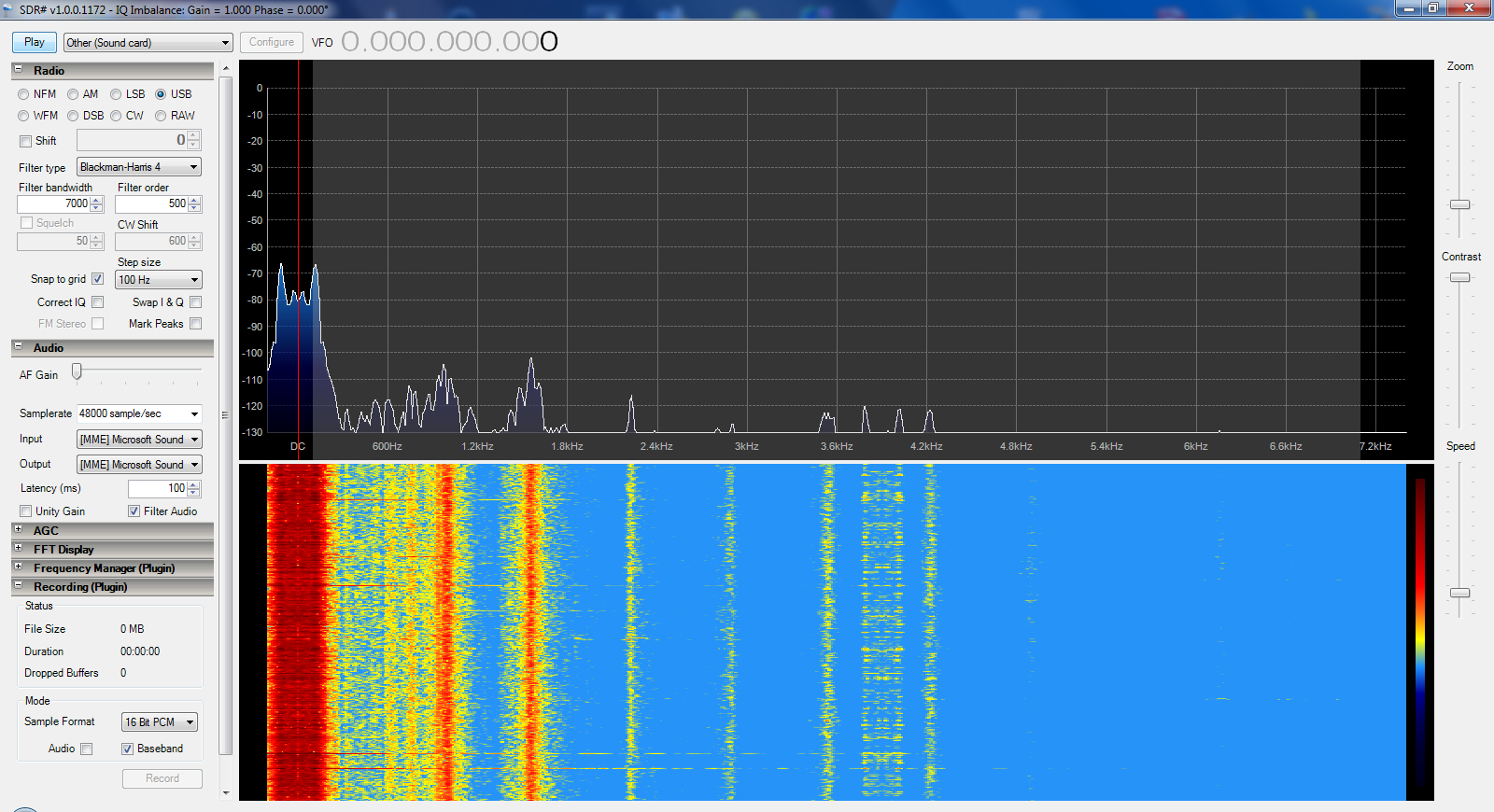
Have you thought of the simple idea of a radially arranged "pipe organ"  device with PVC piping ? For wind direction, as well as  sound analysis it could be interesting.   You might even be able to calculate temperature from the differences in response to the same wind by different size pipes.  For sound detection, with different diameters and lengths of PVC pipe you could really get down into the low frequency ranges while excluding other noise. With really big pipes and using the SDR# program as a filter you could detect  and localize the infrasounds of a tornado or thunderstorm from miles away maybe?  Have fun with this - I'll be following your project!

  Are you sure? yes | no

Dave Merrett wrote 04/24/2016 at 22:47 point

Thanks. Irealised early on there's many ways wind-excitation can be directionally modulated into sound. Its clearly also possible to simply use thin 'sticks' ( of , eg plastic), that directionally vibrate at length-proportionate frequencies. A sprung-mass could be the resonator, then a piezo element to transduce.

  Are you sure? yes | no

Similar Projects

Does this project spark your interest?

Become a member to follow this project and never miss any updates