0%
0%
Square Wave Box
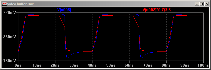
Silabs-based dual channel 1Hz→100MHz square wave generator with 1.2→5 volt outputs and an easy to read LED display.
 matseng
Become a Hackaday.io member
Already have an account? Log in.
Just one more thing
To make the experience fit your profile, pick a username and tell us what interests you.
Pick an awesome username
hackaday.io/
Your profile's URL: hackaday.io/username. Max 25 alphanumeric characters.
Pick a few interests
Projects that share your interests
People that share your interests


 Tauno Erik
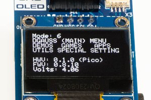
 Andy Geppert
 Marius Taciuc
What is the chip at the heart of this DDS ?
I'm about to build a quick&dirty freq generator with 74HC gates from my drawers, so I suppose it doesn't fit your bill :-)