Close
0%
0%

Quick & Dirty Frequency Generator

Because I need it, I can and I'm cheap. So maybe I'll do.

Similar projects worth following
I need a convenient frequency source to test my circuits. It must be small, not too power-hungry, easy to build using the pieces I collected from other projects...
This time I try to do before I write, but I can't keep myself from creating more projects. Sorry guys :-P

Power supply : 3 AA alkaline batteries (4.5V) or 5V external input.

Primary frequency source : 16.384.000Hz miniature TCXO (off eBay, I forgot where it comes from)
There could be a secondary souce, probably 10MHz from OCXO or Rb (less than 50MHz)

Predivider : made of a 16-bits ALU with integrated feedback (IDT7381, at least 40MHz capable)

Divider : 2×74HC4040 divide by 2^24 (down to about 1s when prediv is bypassed)

Mixed electronic and mechanical control. Hexa rotary knobs and LED displays (TIL311 for now, DYPLED later)

Maybe one day I'll add a PLL to smoothe the ouput but I'm fine with the jitter because it makes only 2 edges, 25ns apart, on the 'scope

2016-10: Project->shelved. I got a couple of ready-made DDS that are more flexible (yet more awkward to use). No need to reinvent this wheel...


I thought, why buy a frequency converter board ?

I promise, at first, I just wanted to connect a 4017 and a couple of 4040. But when I realised I have a hammer lying around, so hey, why not.

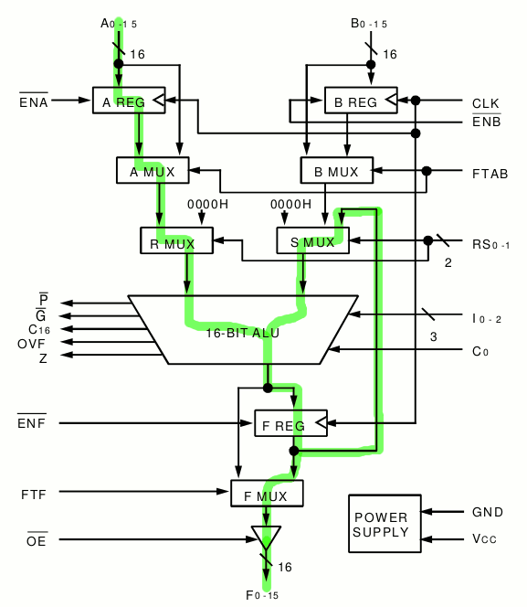
The IDT7381 is a 16-bits ALU that cost me only a few bucks and can work at 25ns (40MHz) when looping with its internal buffer. This is exactly what I first intended to do with a 74HC574 and a 74F181. Chaining to 8 bits without a normal carry output was a PITA.

Initially I wanted to use only 3V for the power supply but the 74HC4040 would not be fast enough. Bumping up the supply voltage enables me to go a bit faster so an external input is possible.

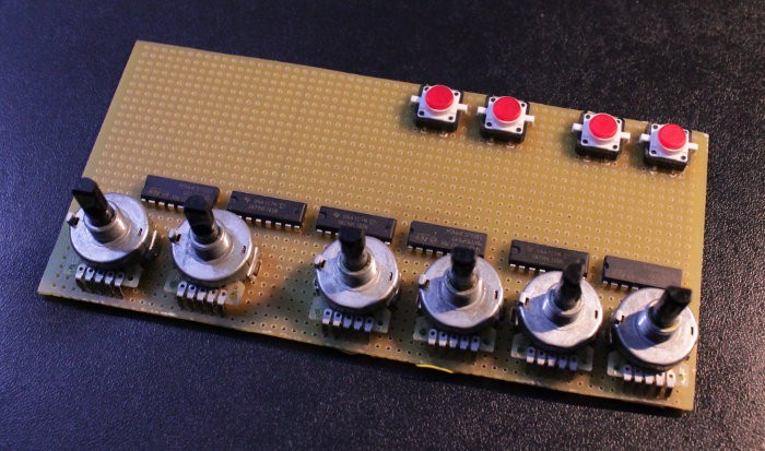
Input parameters are set with rotary buttons. They are pretty glitchy so I need to enable data with a push-button or something. The IDT7381 has a latch enable input that is meant for pipelining, this is handy in this case too !

Display is with TIL311 in the first version. They draw power, I know... but the DYPLED is not ready yet. Maybe I could even test the DYPLED with this project's interface board...

The mechanical switches can be overriden by an external digital signal, I'm adding some 74HC595, and 74HC165 to read the switch positions.

This thing borrows a LOT of ideas of, and parts from, the #Discrete YASEP and #Yet Another (Discrete) Clock


Logs:
1. Notes on using a pipelined ALU for frequency division
2. Doubling the frequency
3. Project rebirth ?
4. Alternatives
5. The (semi-aborted) front panel

idt7381__.pdf

Datasheet of the IDT7381 ALU that is used as frequency divider.

Adobe Portable Document Format - 255.62 kB - 03/27/2016 at 00:16

Preview
Download

  • The (semi-aborted) front panel

    Yann Guidon / YGDES05/01/2016 at 18:13 0 comments

    I recently started hacking a control interface for the system but is soon got out of hand. For example, I thought that I could get the whole thing, (buttons, ALU, display and dividers) on the same pretty narrow board.

    It turns out, I can't really. I added a "bypass" system with '165 and '595 shift registers to read the buttons, and override their value, to provide external control (and debouncing, or even smooth fading) and there is not even a TIL311 or #DYPLED in sight.

    So I moved the frequency/signal processing to another board behind it.

    Then, other projects happened.

    Anyway, I'm now having a pretty cool clock source and some PLLs so the story is not over. Yet.

  • Alternatives

    Yann Guidon / YGDES04/25/2016 at 19:46 7 comments

    I just discovered this chip : the STATEK PXO-1000 integrated quartz oscillator with integrated predividers.

    http://pdf.datasheetarchive.com/datasheetsmain/Datasheets-8/DSA-154595.pdf

    Yes it's pretty practical to hack a tiny frequency generator with a minimum part count. I ordered a few of these antiques that don't seem to grow old.

    Of course "I could do this with a PIC" but the total absence of programming is worth it :-)


    In the same vein, after a hint from @K.C. Lee, I got myself a bunch of PLLs.

    Actually it's called a "zero-delay clock buffer" with 8 outputs but the CYPRESS CY2308SC-4 also works as a frequency doubler that can output between 10MHz and 133MHz.

    By playing with the feedback signal, not only I can smooth the signal (reducing the jitter) but also bring the frequency much higher. I expect my Rb source to output 20MHz, which will be halved by the ALU, but I can reach up to 120MHz :-)


    Another discovery from http://www.jmargolin.com/vgens/vgens.htm :

    "The BRM used by Atari was the 7497. The 7497 is a 6-bit BRM. With a digital input of 63, it will produce 63 output pulses for every 64 input clocks. With a digital input of 1 it will produce one output pulse every 64 input clocks. Two 7497s were chained together to produce a 12-bit BRM. The data sheet for the 7497 is available here (PDF 282KB)."

    So yes there is a simpler, faster (better) way to perform the frequency division.

    Of course, all of this would run faster, better and take less power if I just used a A3P250.

  • Project rebirth ?

    Yann Guidon / YGDES04/15/2016 at 00:00 0 comments

    The circus of the sub-projects continues !

    I couldn't wait to complete this project and #ScoPower was hacked in one hour. So why bother anymore ?

    Well, ScoPower led to #Active scope probe with no dedicated power supply and at one point I'll have to check the frequency response, so I need a frequency generator that is able to sweep though low and high frequencies.

    There is a problem, though : this frequency generator can only output a square wave, up to 40MHz.

    Now I have different solutions:

    • get a DDS module (Nooelec has one for 15$)
    • Use a FPGA to do the DDS thing, my Actel chips can go pretty high if well designed, and I can learn to control the PLL. There would be a 8-bit output (representing a sine stored in blockram) going to a fast/video DAC
    • Do it the hard way with discrete parts (but it would not have the same performance)

  • Doubling the frequency

    Yann Guidon / YGDES03/28/2016 at 20:39 4 comments

    I had overlooked a little detail in my initial system analysis.

    Even though the input frequency can reach 40MHz (due to the internal 25ns cycle time), the maximum possible output frequency is 40/2=20MHz, which could be better.

    It is not possible to go higher with this circuit. However, with 2 parallel circuit, there must be a way... One ALU is read during the input clock low phase, the other is read during the high phase.

    Mathematically it's not a problem because the system is highly linear. Since one accumulator increases its value by N at each cycle, it should advance by 2N after 2 cycles. Now if there are 2 separate accumulators, both advance by 2N. The system could be extended to even more phases (powers of 2 work best) if needed.

    How would it work ?

    • Accumulator A is reset to 0
    • Accumulator B is reset to the advance value N
    • Both advance with the value 2N (N is shifted left by 1 position, MSB is ignored, LSB is 0)

    I'm sure I'm reinventing the wheel but... it's fun and doesn't cost me much. The only critical thing is to keep the accumulators in synch so they must be loaded simultaneously. Manual changes will require the push of a button (to load the A and B registers), until I automate this.

    Assuming the input clock's duty cycle is 50%, A's MSB is output on the low phase and B's MSB is output on the next high phase. The output jitter would be only 12ns now :-)

    I'm sure the performance, speed, consumption etc. would be much better with a FPGA (Most FPGA even have a configurable PLL) but it would be cheating :-D

  • Notes on using a pipelined ALU for frequency division

    Yann Guidon / YGDES03/28/2016 at 08:08 0 comments

    Initially, I wanted to use a 74F381 (4-bits ALU) and a 74HC574. Then I tried to extend the 4-bits add function to 8 bits but cascading is hard because there is no carry output, but propagate and generate signals. The Generate signal could be used alone when the carry input is not used but apparently it needs an inverter. From there, it went downhill.

    Then, looking at my notes at https://hackaday.io/project/8121-discrete-yasep/log/28438-what-chips-for-the-alu I saw that I had the ideal solution. From the datasheet :


    The IDT7381 is a high-speed cascadable Arithmetic Logic Unit (ALU).

    These three-bus devices have two input registers, an ultra-fast 16-bit ALU and 16-bit output register. With IDT’s high-performance CMOS technology, the IDT7381 can do arithmetic or logic operations in 25ns. The IDT7381 functionally replaces four 54/74S381 four-bit ALUs in a 68-pin package.

    The two input operands, A and B, can be clocked or fed through for flexible pipelining. The F output can also be set into clocked or flow-through mode. An output enable is provided for three-state control of the output port on a bus.

    The IDT7381 has three function pins to select 1 of 8 arithmetic or logic operations. The two R and S selection pins determine whether A, B, F or 0 are fed into the ALU. This ALU has carry-out, propagate and generate outputs for cascading using carry look-ahead.


    The advantages are pretty significant :

    • only one chip is needed for all the functions (computation and latching)
    • it's 16-bits wide (and not just 4 or 8 bits)
    • it draws less power
    • it's faster (it easily reaches 40MHz, providing a 20MHz square signal output).
    • No programming is required, just set the 16-bits divider value on the A port and get the divided frequency on the MSB of the result (F15 bit).
    • The remaining output bits could be used to address a fast SRAM to generate arbitrary waveforms (I would need a fast DAC, such as a RAMDAC. Oh wait: I have RAMDACs).
    • Another pretty useful feature is the ability to latch the inputs. This provides a glitch-free frequency change, since my hex rotary switches are pretty dirty. From there on, it's possible to cut the connexion between the rotary switches and the port, under software control, with 74HC165 and 74HC595, to smooth the frequency changes with a microcontroller or a Pi.

    The chip would be used this way :

    The connexions are:

    • Input B : unused, tied to GND.
    • Input A : Division ratio, 16 bits coming from the rotary switches and the 74HC595.
      Value 0 is detected as "bypass" value. It should be FFFF (with the carry input set) but then the digital reading would be harder to interpret.
    • Output : divided frequency on F15
    • /ENB : pointless, tied to GND.
    • /ENA : one pulse low to latch the new frequency. Tied to GND initially for manual operation, such that it is updated at every cycle.
    • FTAB : GND (flow-through disabled)
    • /ENF : GND (enable the F register during every cycle)
    • FTF : GND (no flow-through, should reduce the jitter)
    • CLK : clock input (40MHz, can it go faster ?)
    • /OE : GND (enable the F port output)
    • C0 : GND (Carry in. I thought about feeding a noise generator/LFSR to add jitter, let's see later)
    • C16, OVF, Z, P, G : open/unconnected
    • RS0, RS1 : 00 (select operands A and F)
    • I0, I1, I2: 110 (addition)

    It's actually pretty simple : except I0 and I1 all fixed inputs are GND :-)

View all 5 project logs

Enjoy this project?

Share

Discussions

Eric Hertz wrote 03/28/2016 at 09:33 point

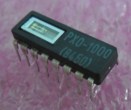
Hah! Had no idea ALUs came like this... then did a search on digikey and... apparently all there is these days is 74-series, as I kinda thought :/

  Are you sure? yes | no

Yann Guidon / YGDES wrote 03/28/2016 at 12:48 point

Wrong store then. Try eBay. However I've only got pulls, no new, some have bent pins... But one of them should work.

  Are you sure? yes | no

Eric Hertz wrote 03/29/2016 at 04:13 point

I guess it's more a confirmation of my original thought-process, being that things like glue-logic, latches, etc. make sense to stay around and continue to be improved in this era, but larger-scale things like ALUs are application-specific enough to be used mainly only *inside* other things like microcontrollers... so it doesn't make as much sense to keep (and improve) 'em as separate units. OTOH, it'd sure make things like building custom processors more easy ;) And, a nice surprise that they even kept 'em 'round long enough to do a 16bitter, I would've never expected. Trying to imagine what sorts of devices they'd've been pulled from...

  Are you sure? yes | no

Yann Guidon / YGDES wrote 03/29/2016 at 04:17 point

Probably from radar/sonar/stuff like that, that need heavy parallel computations, such as FFT or other DSP...

  Are you sure? yes | no

Does this project spark your interest?

Become a member to follow this project and never miss any updates