 Bharat Kumar
What are the problems ?
- žInstant help is not provided after accident.
- žIf people are not familiar that how to get help.
- žIt can be possible that no one is present to call services at the time of accident.
- žIt is difficult to search the nearest place from where help can be provided.
- žIn many cases instead of providing help, people ignores and don’t wants to involve themselves.
- žIt is difficult to control emotions and handle situation when suffered with accident.
- žDevice may not be available to call services.
System Introduction
Main components of the system- Crash sensor, GPS, Emergency call system, receiving end. Crash sensor will be used to sense the accident. It can be made with the help of arduino board or else we can buy it from outside and use it. It will be placed in front end, last end and in sides of vehicle to sense accident from all sides of vehicle. Crash sensor will activate the GPS and Emergency call system. GPS (Global Positioning System) will be used to get current location of vehicle and nearby places and their telephone numbers. Emergency calling system will generate a call to these numbers. And these receiver ends will help the persons.
Functional Requirements
Hardware used
- Air bag sensors
- GPS receiver CMOS
- Camera
- Flash memory
- Power supply
- Cellular phones
- On-board microprocessor
Interface Requirements
HMI or User-Interface Elements The system consists of the following elements: 1) SOS Button This button starts and ends the manual emergency call. The manual call will only be started when the button is pushed for at least 2 seconds. -A call will be aborted or ended immediately when pushing the button for at least 1 second during a call or the initiating of a manual or automatic call. -By starting a call, an acoustic feedback (beep for 0.5 sec) will be played. -By ending/aborting a call an acoustic feedback (2 beeps in 0.5 sec) will be played. The call must be given the highest priority. 2). System status indication with color status light or alphanumerical display. The following status should be indicated- – That no mobile phone is connected to the Call system, if the Bluetooth connection is being in progress, – The system is powered ON and ready to make calls, – A call is being connected or in progress, – That the one system may not be functioning properly, 3) Map display -Shows the location of vehicle on map screen at task handling side
Non functional Requirement
Target Environment:1)Cost: Because the
Call System will be present in every new car, including economy as well as
luxury models, cost will be high and reduction will be of high priority.
2) GSM/GPS Reception Sensitivity: The Call system shall provide sensitive and reliable reception since it will be in a protected location inside the car and may need to use an antenna.
3) Power Consumption: The Call System shall have low power consumption, especially in standby, to avoid draining battery power when the car is immobile for a long time.
4) Easy Software Integration: suppliers and third party software companies shall be easy to integrate.
5) Real-Time Capabilities: The Call System gathers vehicle which may require responding to interrupts with a low latency.
6) Over-the-air device management: Because the Call platform will probably host new applications in the future, secure software downloads and patching shall be easily possible via air.
Scope
We are not able to fully protect ourselves from accidents but we can prevent deaths by providing emergency services.
Application
- Emergency services can be provided.
- Turn-by-turn navigation directions to a human in charge of a vehicle or vessel via text or speech.
- Directions fed directly to an autonomous vehicle such as a robotic probe.
- Traffic congestion maps (depicting either historical or real time data) and suggested alternative directions.
- Information on nearby amenities such as restaurants, fueling stations, and tourist attractions.
- Emergency call system can...
 alexwhittemore
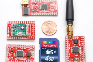
 Felix Rusu
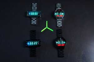
 tlnvwmz
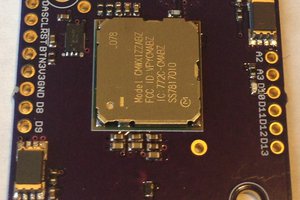
 Kris Winer