 Reed Foster
With an almost complete loss of data between the SPI controller and the SSD1306, I decided that I should use just the processor core because I know that at least the processor core runs how it is supposed to (how the simulation runs) on the FPGA itself. With software SPI, I ran into a whole new set of problems. With an 8 bit immediate width, branch instructions cannot cover very much code. Furthermore, a loop that executes 256 times is not possible, so one cycle of the loop must be unfolded. By controlling the io ports with software and unfolding a loop, my code space had grown so large that the outer loop (I have 3 nested loops) was so wide I could not branch from end to end. The solution: add intermediate branches. Pseudo-code:
jmp 2; skips next two instructions when loop is executed
; they are only executed when branched/jumped to from
; elsewhere in the program
jmp outerloop_start; intermediate for backwards jump
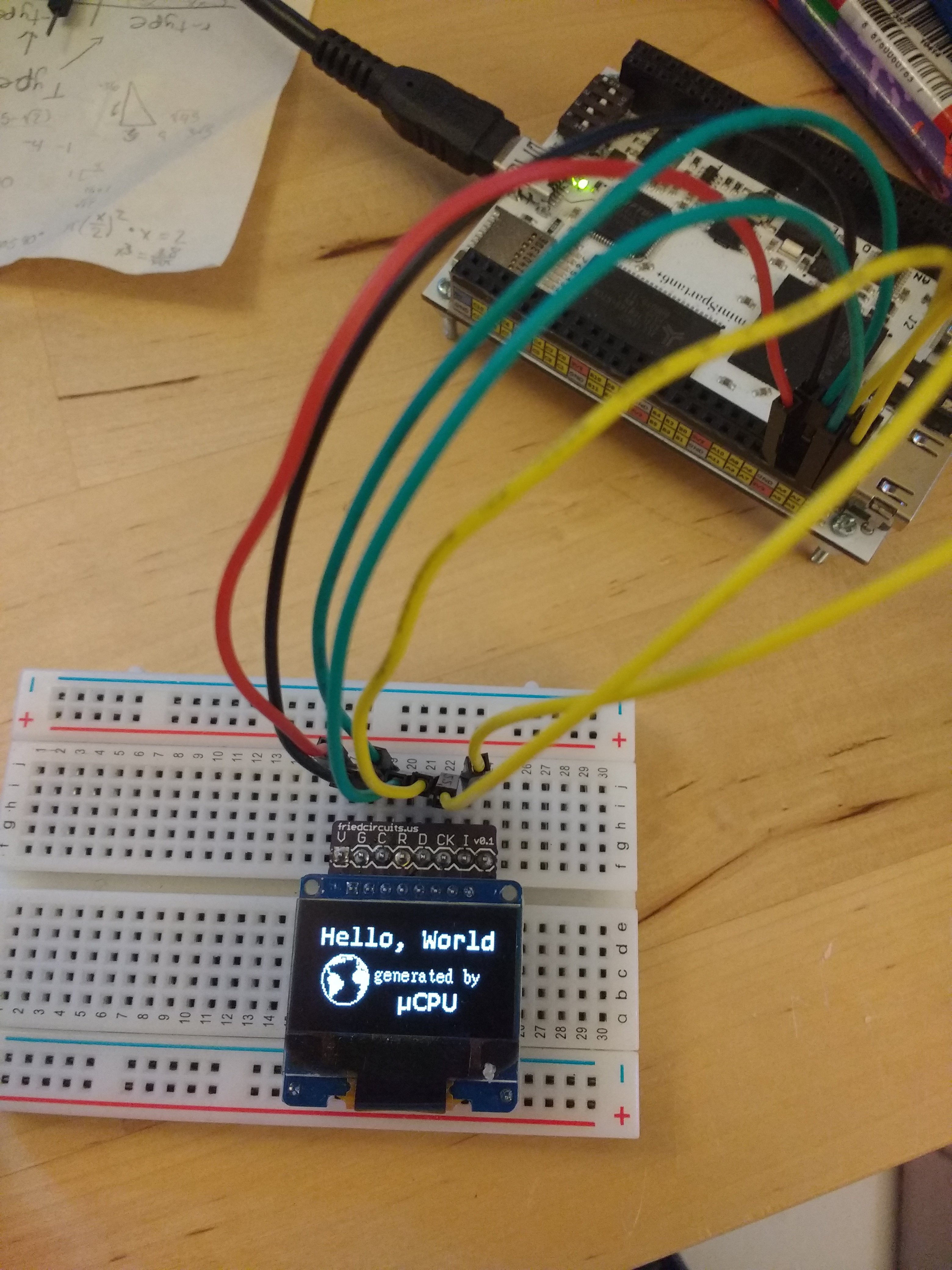
jmp outerloop_exit; intermediate for exit branchWhen I was using the vhdl SPI controller, one of the clear indicators that the SSD1306 wasn't receiving all of the data was the dimness of the screen. I did a couple tests with an arduino, and when I disabled the charge-pump configurations, the display was unlit connected to 3.3v and only very dim with 5v. I have yet to figure out why the display was able to receive some commands and not others, but I eventually will troubleshoot that with a logic analyzer or something like that.
Using this indicator, I was able to tell whether or not the software SPI worked fairly easily. Unfortunately, it took me forever to figure out what was going wrong after the initialization; there wasn't any comprehensible data that appeared on the display. I tested a pattern of bytes that I expected would fill the top row only, but found a much different result; the 16 bytes that I sent were arranged vertically.
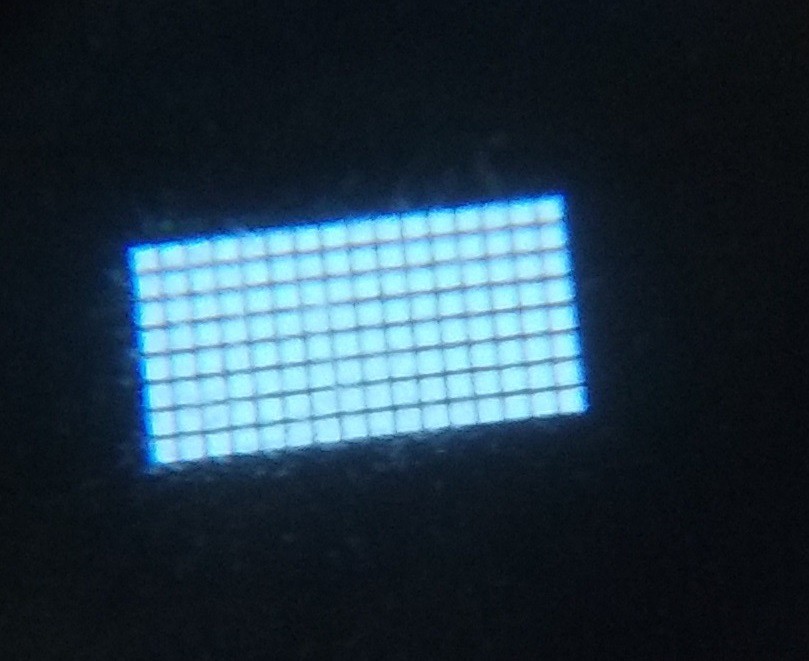
After discovering this, I looked at the datasheet for the SSD1306 and discovered that I simply misunderstood how the device was interpreting the data I sent it. After visiting stackexchange for a couple conversion methods between hex and binary strings in python, I produced a simple program that remaps the bits in the .xbm file format (the one that I had been using to draw and save black and white images) to bits that can be sent, byte by byte, to the SSD1306 without additional processing on the FPGA. The end result:
Zoomed in (I augmented my phone camera with a small lens from an ancient video camera). Individual pixels are visible.

Assembler code:
//PortD pin assignments (nc means no connection)
//assignment     set-bitmask (or)    reset-bitmask (and)
//pin0 => mosi   00000001 | 1        11111110 | 254
//pin1 => sclk   00000010 | 2        11111101 | 253
//pin2 => dc     00000100 | 4        11111011 | 251
//pin3 => rst    00001000 | 8        11110111 | 247
//pin4 => ss     00010000 | 16       11101111 | 239
//
		//SET RST and SS (rst, ss = 1)
		li r7, 255    //set par (page address register) to io bank
		li r2, 24     //bit mask for rst (high)
		lb r1, 255(r0)//load spi reg
		or r1, r1, r2 //apply bit mask
		sb r1, 255(r0)//store spi reg
		//RESET RST (rst = 0)
		li r2, 247    //bit mask for rst (low)
		lb r1, 255(r0)//load spi reg
		and r1, r1, r2//apply bit mask
		sb r1, 255(r0)//store spi reg
		// DELAY LOOP (loops for ~4us to hold reset low for length required by ssd1306)
		// while (true) {
		//  if (i = 10) {break;}
		//  else {i++};
		// }
		li r4, 10         //r4 is stopval
		li r3, 1          //r3 is incrementval
		li r1, 0          //r1 is counting reg
delay_start:		sub r2, r4, r1    //r2 compares r4 and r1; if neg, then r1 > r4; if zero, r1 = r4
		bez r2, delay_exit//if r2==0, then exit loop
		nop               //delay slot
		bez r0, delay_start//infinite backwards loop
		add r1, r1, r3    //increment r1 by r3
		//SET RST (rst = 1)
delay_exit:		li r2, 8      //bit mask for rst (high)
		lb r1, 255(r0)//load spi reg
		or r1, r1, r2 //apply bit mask
		sb r1, 255(r0)//store spi reg
		//RESET D/C (d/c = 0; put ssd1306 into command mode, which it should already be in)
		li r2, 251    //bit mask for d/c
		lb r1, 255(r0)//load spi reg
		and r1, r1, r2//apply bit mask
		sb r1, 255(r0)//store spi reg
		//COMMAND LOOP (sends 25 init commands + 6 memory config commands; prepare ssd1306 for buffwrite)
		// while (true) {
		//   if (i = 31) {break;}
		//   else {
		//     ss = 0
		//     while (true) {
		//       if (j = 8) {break;}
		//       else {
		//         sclk = 0;
		//         mosi = byte[j];
		//         sclk = 1;
		//       }
		//     }
		//     ss = 1;
		//   }
		//loop setup
		li r1, 0      //r1 is counting reg
		li r3, 1      //r3 is incrementval
cmdloop_start:		li r4, 31     //r4 is stopval
		sub r2, r4, r1//r2 compares r4 and r1; if neg, then r1 > r4; if zero, r1 = r4
		bez r2, cmdloop_exit//if r2==0, then exit loop
		//loop contents
		li r7, 12     //set par to rom[commands]
		lb r6, 0(r1)  //r6 holds the byte to be send via spi
		li r7, 255    //set par back to io bank
		//reset ss
		li r5, 239    //bit mask to reset ss
		lb r4, 255(r0)//load spi reg
		and r4, r5, r4//apply bit mask
		sb r4, 255(r0)//store spi reg
		//send byte (loop)
		li r2, 0      //r2 is counting reg
cmdbyte_start:		li r4, 8      //r4 is stopval
		sub r5, r4, r2//r5 compares r4 and r2; if neg, then r2 > r4; if zero, r2 = r4
		bez r5, cmdbyte_exit//exit loop if r5==0
		nop           //delay slot
		//sclk low (setup mosi)
		li r5, 253    //bit mask to reset sclk
		lb r4, 255(r0)//load spi reg
		and r4, r5, r4//apply bit mask
		sb r4, 255(r0)//store spi reg
		//mosi
		//shift left unit desired bit is msb, then shift right 7; b7:b1=0, b0=desired bit
		sll r5, r6, r2//shift current bit to msb
		li r4, 7      //shamt for srl
		srl r5, r5, r4//shift msb to lsb
		lb r4, 255(r0)//load spi reg
		li r3, 254    //bitmask to reset mosi
		and r4, r4, r3//clear mosi bit of spi reg
		or r4, r5, r4 //combine spi reg with mosi_out
		sb r4, 255(r0)//store spi reg
		//sclk high (latch mosi)
		li r5, 2      //bit mask to set sclk
		lb r4, 255(r0)//load spi reg
		or r4, r5, r4 //appy bit mask
		sb r4, 255(r0)//store spi reg
		//end loop
		li r3, 1      //reset constant loop variables; r4 (stopval) reset later
		bez r0, cmdbyte_start//infinite backwards loop
		add r2, r2, r3//increment r2 by r3
		//set ss
cmdbyte_exit:		li r5, 16     //bit mask to set ss
		lb r4, 255(r0)//load spi reg
		or r4, r5, r4 //appy bit mask
		sb r4, 255(r0)//store spi reg
		//end loop
		li r3, 1      //reset constant loop variables; r4 (stopval) reset later
		bez r0, cmdloop_start//infinite backwards loop
		add r1, r1, r3//increment r1 by r3
		//SET D/C (d/c = 1; put ssd1306 into data mode)
cmdloop_exit:		li r7, 255    //set par to io bank
		li r2, 4      //bit mask for d/c
		lb r1, 255(r0)//load spi reg
		or r1, r1, r2 //apply bit mask
		sb r1, 255(r0)//store spi reg
		//DATA LOOP (sends 1024 bytes of data to gddram in ssd1306
		//
		// i = 0;
		// while (true) {
		//   r7 = i;
		//   r6 = mem(0);
		//   k = 0;
		//   cs = 0;
		//   while (true) {
		//     sclk = 0;
		//     mosi = r6(k);
		//     sclk = 1;
		//     k++;
		//     if (k == 8) {break;}
		//   }
		//   cs = 1;
		//   j = 1;
		//   while (true) {
		//     cs = 0;
		//     k = 0;
		//     while (true) {
		//       sclk = 0;
		//       mosi = r6(k);
		//       sclk = 1;
		//       k++;
		//       if (k == 8) {break;}
		//     }
		//     cs = 1;
		//     j++;
		//     if (j == 0) {break;}
		//   }
		//   i++;
		//   if (i == 12) {break;}
		// }
		li r7, 8      //set par to rom[data]
		li r1, 8      //r1 is counting reg (initialized to same value as par)
		li r4, 1      //r4 is countval
outloop_start:		li r5, 12     //r5 is stopval
		sub r6, r5, r1//r6 compares r5 and r1; if neg, then r1 > r5; if zero, r1 = r5
		bez r6, itrfwd//exit loop if stopval is reached
		nop           //delay slot
		//r6 = byte to send
		li r2, 0      //bleh
		add r7, r1, r0//set par to rom[data]
		lb r6, 0(r2)  //r6 holds the byte to be send via spi
		li r7, 255    //set par back to io bank
		//reset ss
		li r5, 239    //bit mask to reset ss
		lb r4, 255(r0)//load spi reg
		and r4, r5, r4//apply bit mask
		sb r4, 255(r0)//store spi reg
		//send byte (loop)
		li r3, 0      //r3 is counting reg
dbyte_start:		li r5, 8      //r5 is stopval
		sub r4, r5, r3//r6 compares r5 and r3; if neg, then r3 > r5; if zero, r3 = r5
		bez r4, dbyte_exit//exit loop if r5==0
		nop           //delay slot
		//sclk low (setup mosi)
		li r5, 253    //bit mask to reset sclk
		lb r4, 255(r0)//load spi reg
		and r4, r5, r4//apply bit mask
		sb r4, 255(r0)//store spi reg
		//mosi
		//shift left unit desired bit is msb, then shift right 7; b7:b1=0, b0=desired bit
		sll r5, r6, r3//shift current bit to msb
		li r4, 7      //shamt for srl
		srl r5, r5, r4//shift msb to lsb
		lb r4, 255(r0)//load spi reg
		li r7, 254    //bitmask to reset mosi
		and r4, r4, r7//clear mosi bit of spi reg
		or r4, r5, r4 //combine spi reg with mosi_out
		li r7, 255    //set par to io bank
		sb r4, 255(r0)//store spi reg
		//sclk high (latch mosi)
		li r5, 2      //bit mask to set sclk
		lb r4, 255(r0)//load spi reg
		or r4, r5, r4 //appy bit mask
		sb r4, 255(r0)//store spi reg
		//end loop
		li r4, 1      //reset constant loop variables; r5 (stopval) reset later
		bez r0, dbyte_start//infinite backwards loop
		add r3, r3, r4//increment r3 by r4
		//set ss
dbyte_exit:		li r5, 16     //bit mask to set ss
		lb r4, 255(r0)//load spi reg
		or r4, r5, r4 //appy bit mask
		sb r4, 255(r0)//store spi reg
		bez r0, 10     //skip intermediate branches, they are only executed when outer loop is repeated/exited
		nop
itrback:		bez r0, outloop_start //jump to start of outer loop
		nop
itrfwd:		bez r0, outloop_exit //jump to end of outer loop
		nop
		//inner loop
		li r2, 1      //r2 is countval
inloop_start:		bez r2, inloop_exit//exit loop if r2 overflowed
		//loop contents
		add r7, r1, r0//set par to rom[data]
		lb r6, 0(r2)  //r6 holds the byte to be send via spi
		li r7, 255    //set par back to io bank
		//reset ss
		li r5, 239    //bit mask to reset ss
		lb r4, 255(r0)//load spi reg
		and r4, r5, r4//apply bit mask
		sb r4, 255(r0)//store spi reg
		//send byte (loop)
		li r3, 0      //r3 is counting reg
lp_dbyte_start:	li r5, 8      //r5 is stopval
		sub r4, r5, r3//r6 compares r5 and r3; if neg, then r3 > r5; if zero, r3 = r5
		bez r4, lp_dbyte_exit//exit loop if r5==0
		nop           //delay slot
		//sclk low (setup mosi) #loopstart
		li r5, 253    //bit mask to reset sclk
		lb r4, 255(r0)//load spi reg
		and r4, r5, r4//apply bit mask
		sb r4, 255(r0)//store spi reg
		//mosi
		//shift left unit desired bit is msb, then shift right 7; b7:b1=0, b0=desired bit
		sll r5, r6, r3//shift current bit to msb
		li r4, 7      //shamt for srl
		srl r5, r5, r4//shift msb to lsb
		lb r4, 255(r0)//load spi reg
		li r7, 254    //bitmask to reset mosi
		and r4, r4, r7//clear mosi bit of spi reg
		or r4, r5, r4 //combine spi reg with mosi_out
		li r7, 255    //set par to io bank
		sb r4, 255(r0)//store spi reg
		//sclk high (latch mosi)
		li r5, 2      //bit mask to set sclk
		lb r4, 255(r0)//load spi reg
		or r4, r5, r4 //appy bit mask
		sb r4, 255(r0)//store spi reg
		//end loop #loopend
		li r4, 1      //reset constant loop variables; r5 (stopval) reset later
		bez r0, lp_dbyte_start//infinite backwards loop
		add r3, r3, r4//increment r3 by r4
		//set ss
lp_dbyte_exit:		li r5, 16     //bit mask to set ss
		lb r4, 255(r0)//load spi reg
		or r4, r5, r4 //appy bit mask
		sb r4, 255(r0)//store spi reg
		//end loop
		li r4, 1      //reset constant loop variables; r5 (stopval) reset later
		bez r0, inloop_start//infinite backwards loop
		add r2, r2, r4//increment r2 by r4
		//end loop
inloop_exit:		li r4, 1      //reset constant loop variables; r5 (stopval) reset later
		bez r0, itrback//infinite backwards loop
		add r1, r1, r4//increment r1 by r4
outloop_exit:		nop           //delay slot
end_program:		bez r0, end_program //halt command, processor idles in endless loop
Because of the complexity of the assembler code to display a still image, I'd probably have to add a j-type instruction or increase the instruction word size to display animations/video.
Discussions
Become a Hackaday.io Member
Create an account to leave a comment. Already have an account? Log In.