 EK
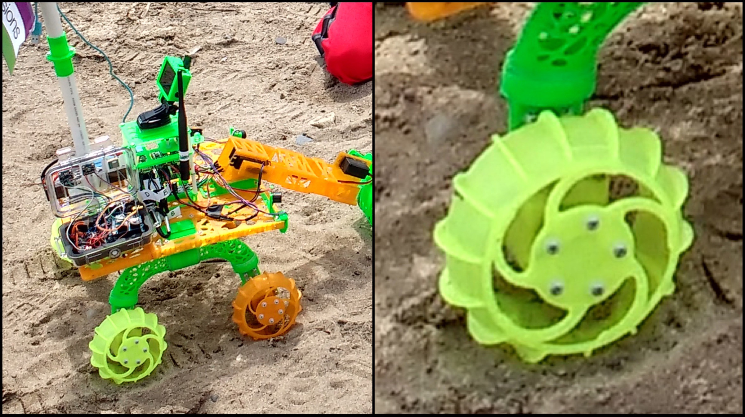
EKRight when we were testing out the autonomous GPS code, one of Bowie's wheels broke
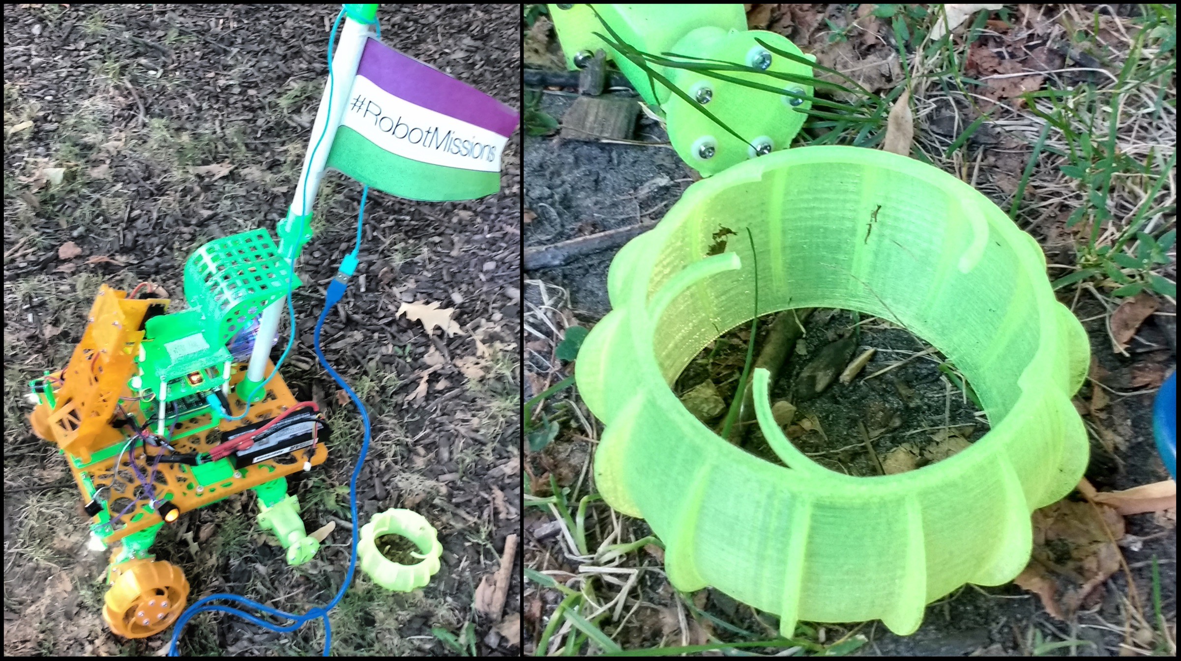
We decided to simulate the wheel, applying a 2N force to the center face of the wheel. It was constrained on the outer rim.
In reality, this would represent the scenario that happens when the robot is turning. The center piece is either being pushed or pulled depending on the direction, since turning is controlled by motor speed and direction (rather than a steering servo).
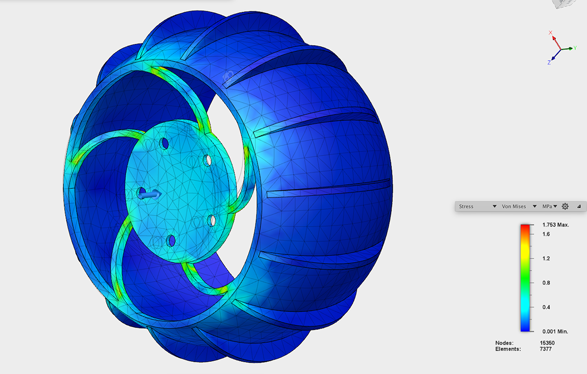
Using Autodesk Fusion 360, we simulated stress on the wheel. Animated view of stress simulation:
Looking at the Von Mises stress simulation, you can see that the weak parts are the spokes:
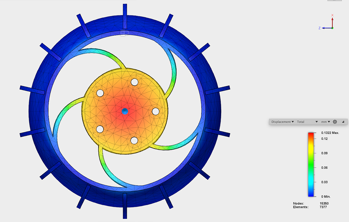
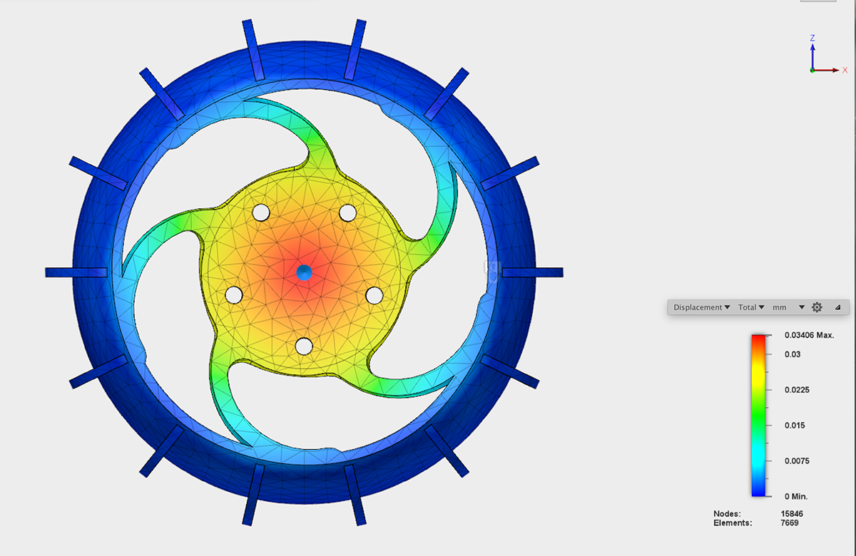
This displacement map shows that the center moves quite a bit, extending to the spokes as well:
For the new wheel, the width and depth of the spokes were increased. Here's the new Von Mises simulation:
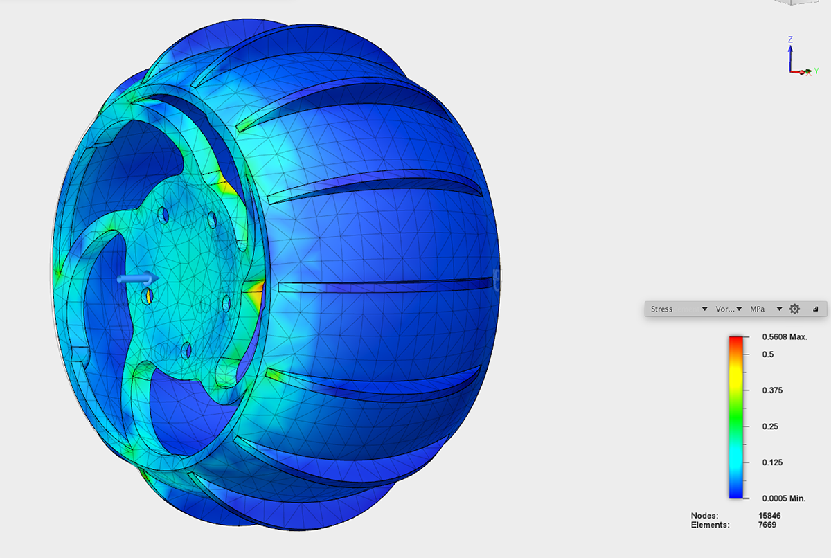
The displacement map doesn't carry out as much to the spokes:
Result: New wheels are holding up so far!
Discussions
Become a Hackaday.io Member
Create an account to leave a comment. Already have an account? Log In.