 sidsingh
The logic board looks physically fine, no burn marks or weird smell, components looks alright and I got a hunch that it may be just the power supply and CFL inverter gone bust and the TV can still be made functional. The inputs were RCA, component, HDMI and VGA and I can definitely use this as a spare monitor or a Raspi Kodi TV for my guest room - only if I can get this working. Two challenges, Step 1 - To verify if the Logic board still works and Step 2 - If logic and screen works then replace the CFL backlight with LEDs.
Step 1: The power and LCD connector pin designations were silk screened on the main PCB... Sweet! The LCD driver board is a generic TV board using Mediatek MTK8227 SoC. The TV is assembled by a reputed manufacturer, but I guess as with all other manufacturers, they source these generic boards from China and dump their logo in ROM and have custom UI and that's about it now a days!
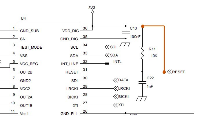
A quick search and you can find a lot of these cheap LCD driver boards based on similar SoC on AliExpress or similar Chinese ecommerce sites. The semiconductors on these boards are mostly obscure components, most of them have no online datasheet or have minimal documentation. After poring over internet for few hours, I got hold of some incomplete datasheet and also a schematic of a different model TV from another manufacturer using same SoC. This was a huge help as there is a pinout of MTK8227 and signal descriptions and now I can trace and probe signals to various peripherals.
The power requirement of the SoC board is simple, all it needs is a 5V, 12V and Gnd. I connected the power headers to a computer PSU, crossed my fingers and switched on. No magic smoke and after a while I checked the ICs and regulators and they were just warm to touch. Seems ok and the red power LED on the front of the panel was ON. Since I did not get the remote along with the TV, I tried the power button on the side of the TV. Nothing happened. I had temporarily illuminated the back of the panel with a LED flashlight and the panel seems blank, no activity, pushed all the buttons and there was nothing! The SoC itself was warm to touch, so I knew it was working, but somewhere something was broken.
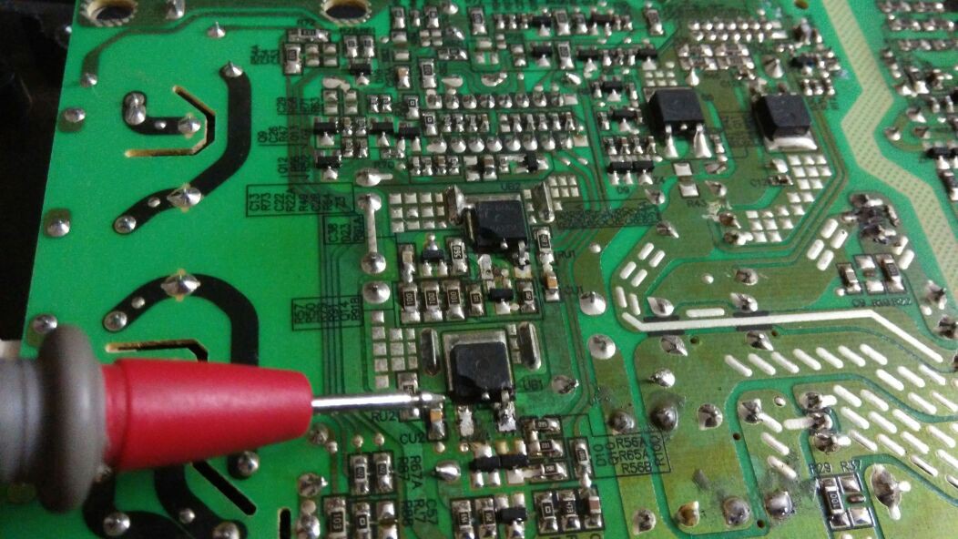
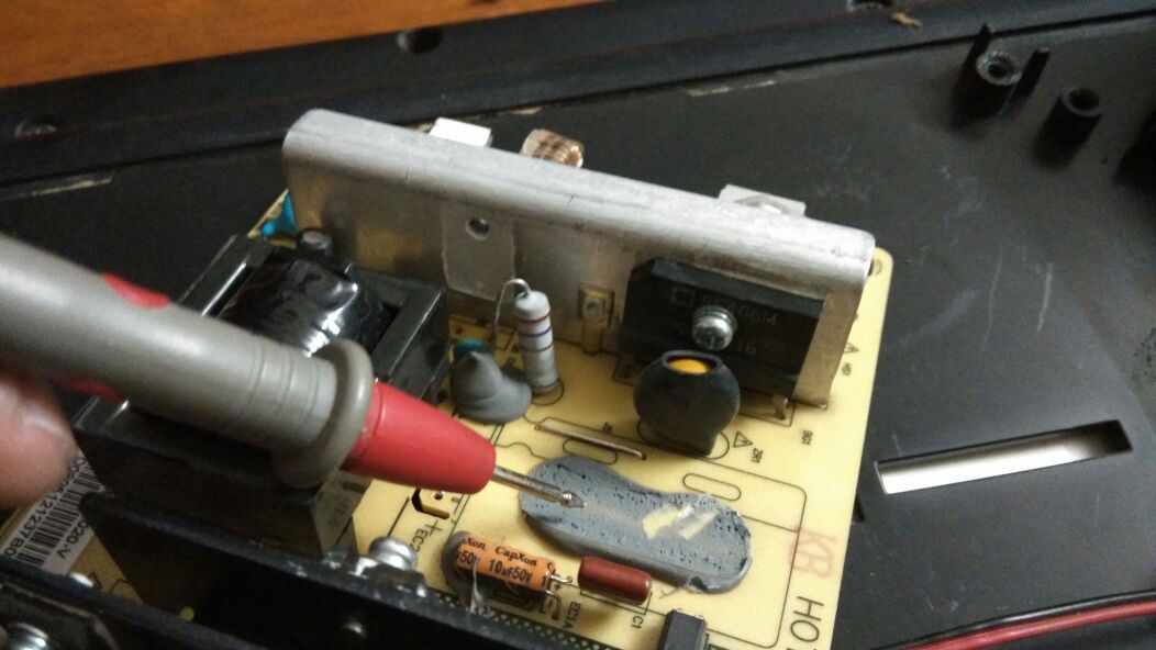
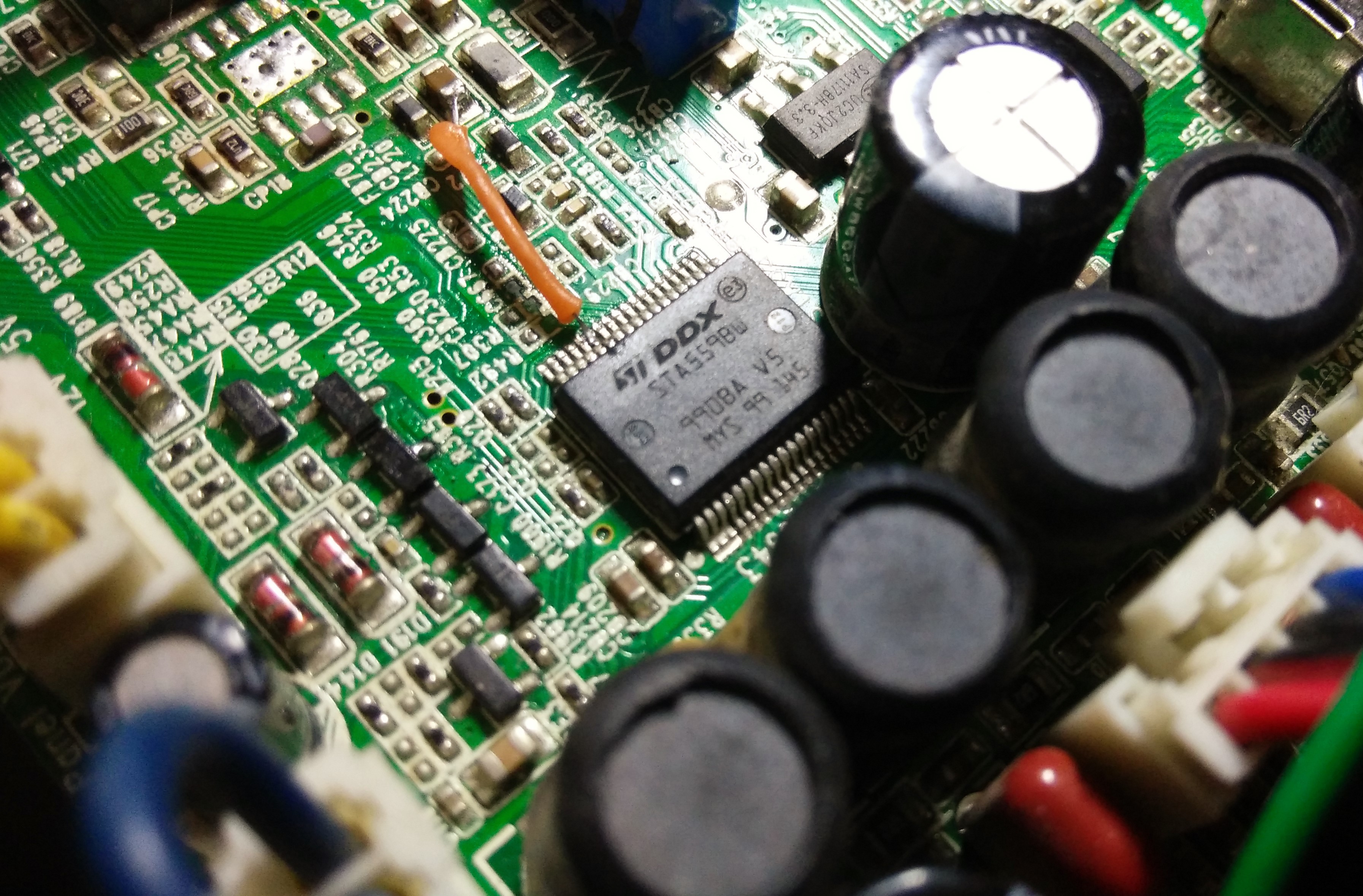
As Dave from EEVblog always says that the first rule of debugging is “thou shall test thy voltages.”, I started with voltage regulators on board, all seems ok except the Vcore 1.2V was reading 0.4V to 0.5V. .... BAM! I found the offending component and It was a 8 pin switching regulator IT7833 1.2V@3A.
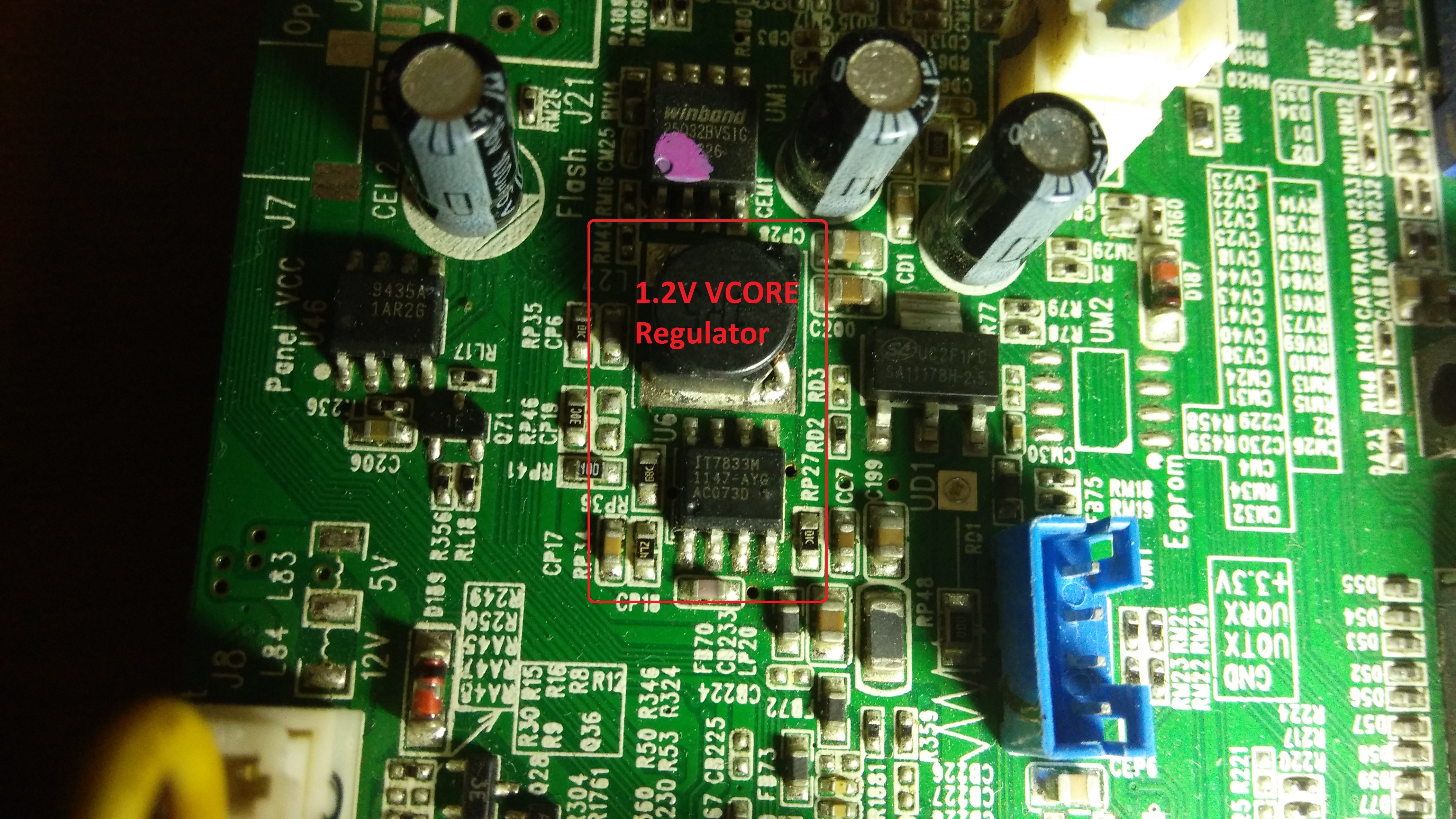
I could not find much information on this regulator, but the one page incomplete datasheet helped me decode the regulator. I didn't had any 1.2V switching buck regulator in my junk box, but I did find my trusty old LM317 regulator and turned the output all the way down to 1.25V and hooked it up to Vcore after desoldering IT7833. Turned ON the power supply and I could see flickers on the dimly lit screen, then the manufacturer logo and finally a 'no Signal' animation on the LCD panel. YAAY - The panel works!!!
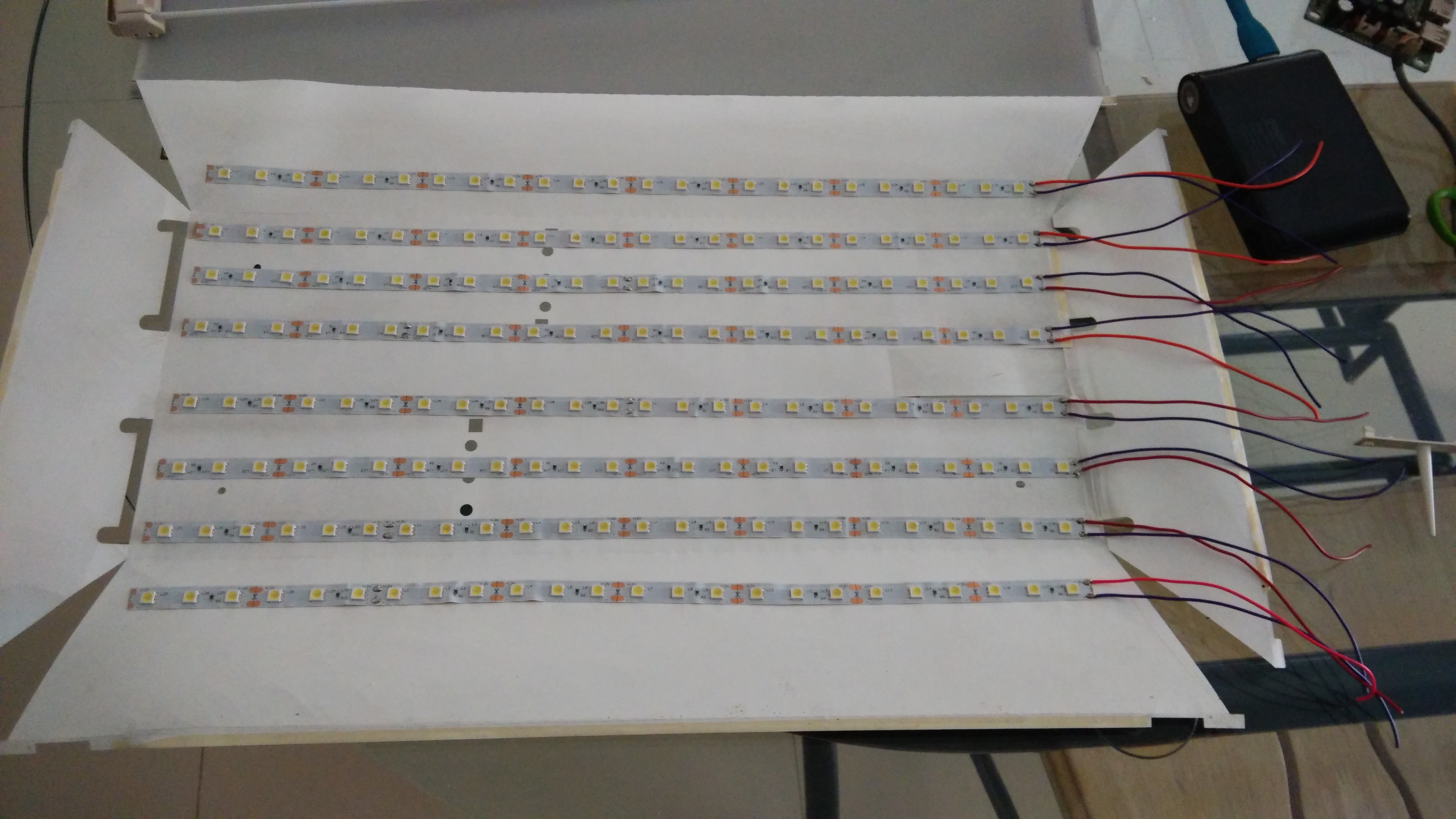
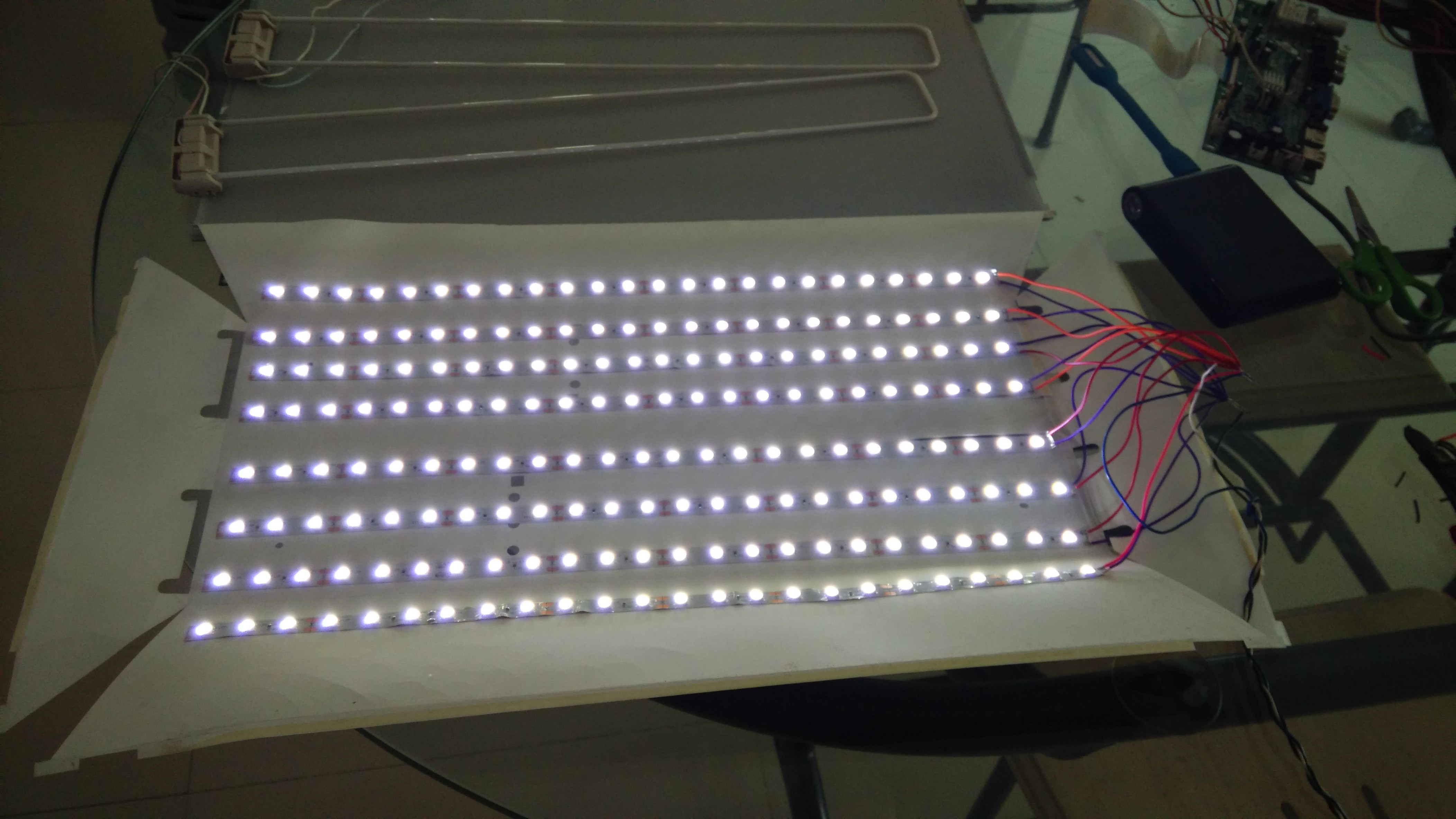
Step 2: This was easy. I had few feet of left over 12V white LED strip, which I cut in eight pieces, stick them inside the white plastic enclosure (for CFL) and wired them all in parallel. The LEDs face the white diffuser stuck to the back of LCD glass.
Warning: Be very careful while handling the CFL as they are very fragile and contains Mercury. Dispose them off in accordance with your local waste disposal laws.
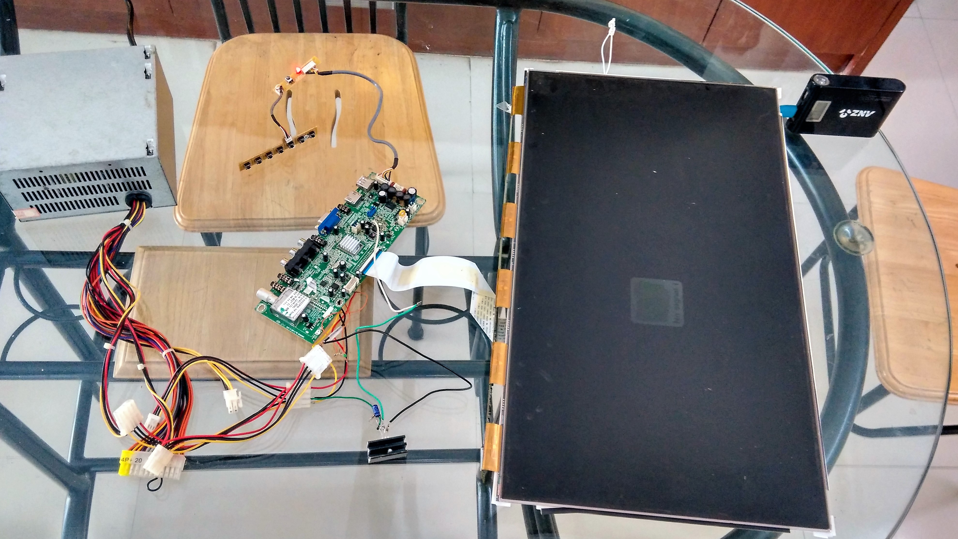
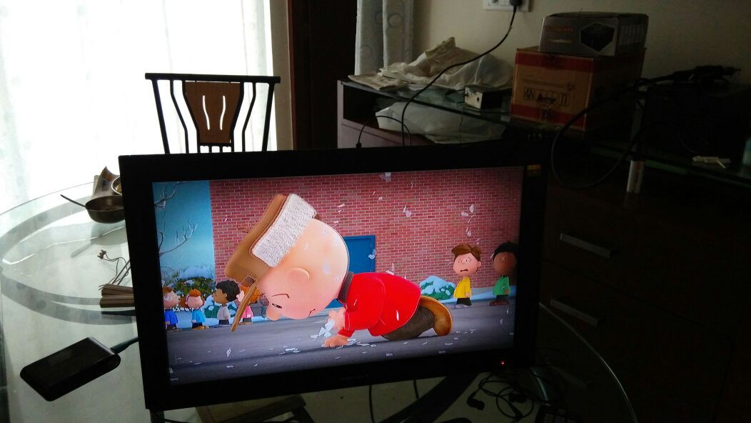
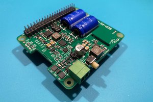
Testing: Connected all the power cables and hooked up my Raspberry Pi to HDMI input and the 1080 HD LCD fired up flawless, looks beautiful .. Awesome :)
I managed to get almost uniform illumination across the screen. I feel I could get much more illumination if I use better and brighter LEDs, for now, this works. Played a movie, works fine. I also programmed a universal remote control with manufacturer code and have a working remote for all basic functions in no time.
There seems to be an issue with audio, could not get anything out of the speakers,...
Read more »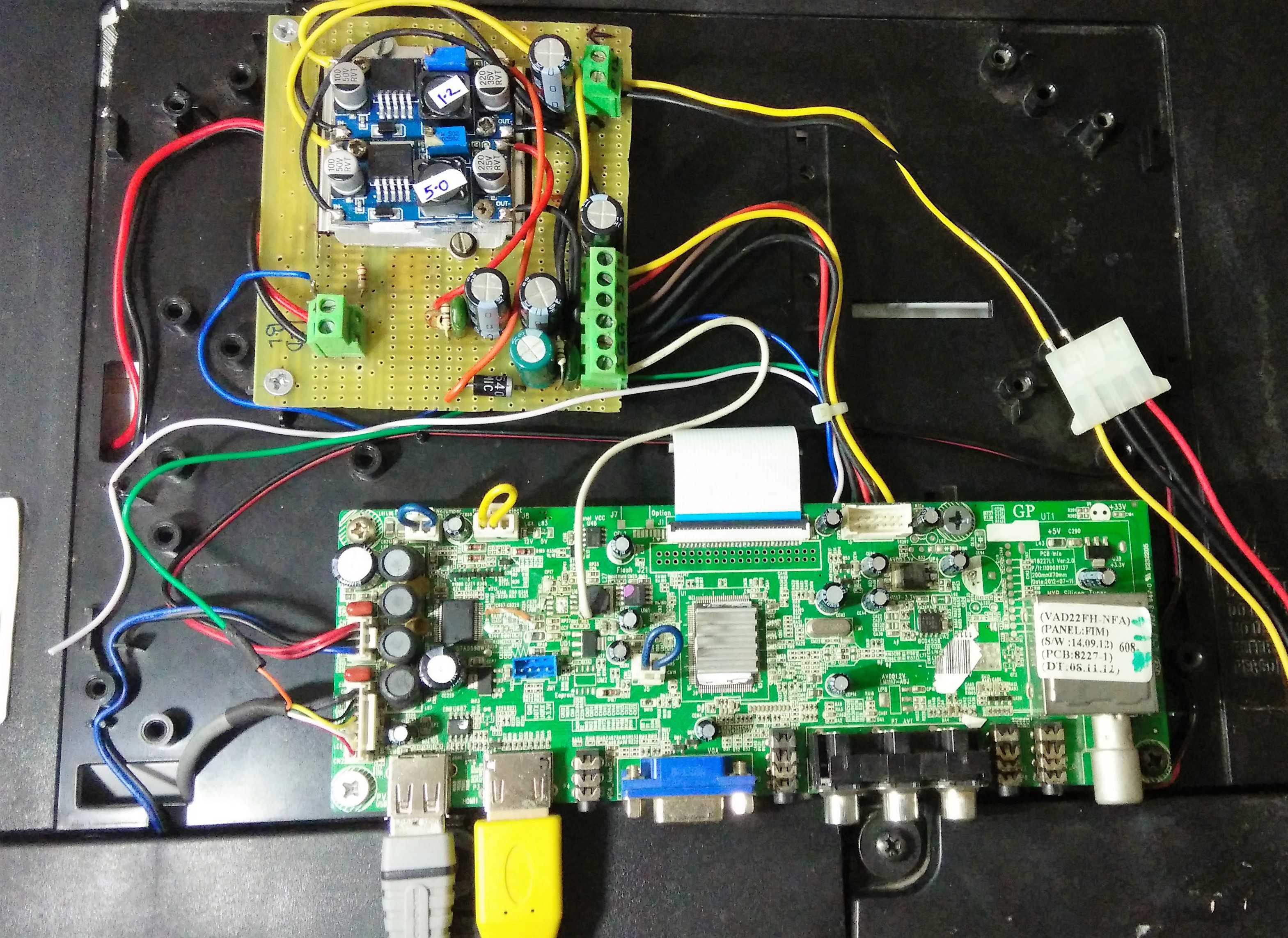


 ElectroBoy
 Denis
Denis
 alcor6502
Hi sir, Great job, many many thanks to you. i like this type of uncommon solution. it's save my time. thanks once again.