Close
0%
0%

City Lights

Network of city lights connected in mesh topology with a control center to observe/control them all in real-time, and even more.

Similar projects worth following
The idea is simple, to try and make our city more energy efficient (less polution, less spending money) when it comes to street lighting. This can be done in two steps which we will describe in the project details section, because it can't fit in this box.

Project code name: ARCADE.

The idea is simple, to try and make our city more energy efficient (less polution, less spending money) when it comes to street lighting. This can be done in two steps:

1) Change all existing light fixtures with LEDs. Currently there are thousands old light bulbs used in street lights here. They are mercury, metal-halide and sodium-vapor based and they are devouring power from the grid to keep the streets lit up. Simple changing from these old technologies to LEDs would make the city spend less money for lighting and more for other community projects. Stopping here would simple be bonkers, so read the second step to see how more money can be spared.

2) Since LEDs can be dimmed, why not make these new lamps somehow smart and make them lower the brightness at small hours when there is almost nobody outside, but keep the street intersections bright at 100%? How about making lamps report to the control center when LEDs ultimately die? This would also spare the city even more money because this way the maintenence does not need to drive around the city looking for broken lights (also, less air polution)! What about making lamps measure their own power consumption and report this to the control center? What about making these smart lamps have an additional output to control secondary light fixture, such as new year's decorations?

***

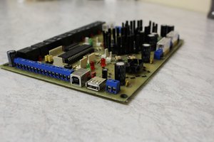
This gives us a rought picture that the project consists of three hardware parts:

A) LED driver,
B) Smart Controller with XBee and
C) Gateway with XBee connected to the data-center PC (or even to the Internet).

There must also be a software component:

A) Server that communicates with Gateway
B) Client application (web based) that communicates with Smart Controllers via XBee connected to the Server

***

Come back later to see how we planned to accomplish this and also the current project state, in the Project Log section.

login.png

Login screen.

Portable Network Graphics (PNG) - 1.55 MB - 04/19/2016 at 17:01

Preview
Download

control2.png

Send various settings to Smart Controller.

Portable Network Graphics (PNG) - 223.41 kB - 04/19/2016 at 17:00

Preview
Download

control3.png

Send calendar events (real time events) to Smart Controller.

Portable Network Graphics (PNG) - 215.48 kB - 04/19/2016 at 17:00

Preview
Download

control4.png

Read last status as reported by the Smart Controller.

Portable Network Graphics (PNG) - 228.90 kB - 04/19/2016 at 17:00

Preview
Download

map.png

Map view of deployed lamps.

Portable Network Graphics (PNG) - 225.92 kB - 04/19/2016 at 17:00

Preview
Download

View all 23 files

  • 1 × XBee DigiMesh 2.4GHz
  • 1 × PIC24F* microcontroller
  • 1 × CS5463 Power meter Cirrus Logic
  • 1 × DS3231 RTC
  • 1 × I2C EEPROM 24LC*

  • Progress on the web app

    trax05/16/2016 at 06:35 0 comments

    • Added multi-language support for the web application.
    • Changed lamp icons to real lamps :-)
    • Fixed some bugs.

    This thing is under the test right now...

  • The thing almost fully finished

    trax05/09/2016 at 08:19 0 comments

    As the title says, this system is amlost fully finished. Few things to finalize and we are ready for testing :-)

  • The Controller (Smart Controller)

    trax03/30/2016 at 08:25 0 comments

    It is clear by now that this project will consist of three hardware components. One of them is the Smart Controller that communicates with Control Center via XBee DigiMesh network.

    It would be great if this controller could control our custom designed LED driver, generic LED drivers and also existing light fixtures using the old-tech-bulbs.

    Making a system that is compatible with all these drivers is a challenge, but since we are designing our own LED driver, we have an opportunity to make it compatible with other generic LED drivers that accept 0-10V PWM input for dimming. It is out of the question that any of those old mercury, metal-halide and sodium-vapor based bulbs can be dimmed (without any modifications to them, or even with) so we can make our Smart Controller turn these on/off and that's it.

    The Controller has to measure power consumption, log it internally with RTC, and report back to the Control Center as soon as possible.

    Switching the loads on/off can be acomplished with solid state relays.

    Dimming is done with 10V PWM output where 10V is generated with a tiny on-board step-up converter.

    RTC will have a backup battery, actually a 1.0F super-capacitor to keep the time runing when power is cut to the lamps in the morning (every morning). This power cutting must be detected by the microcontroller also, in order to save the power consumption with RTC stamp to EEPROM, and to be able to report this information back to the Control Center once power is restored!

    Since we will be using XBee and their DigiMesh system, it *should* be easy to create a network of lamps which will distribute messages from any Smart Controller to the Control Center's XBee (Gateway).
    It turns out that Lamp (street light) poles are some sort of magnets when it comes to traffic, and every now and then a car crashes into one. When this happens, the Smart Controller which is located in one of those poles will be broken/unpowered. Thanks to DigiMesh this means that adjacent poles can continue communicating with each other directly, skipping this broken XBee node. How cool is Mesh topology? The only thing left to do is proove that DigiMesh works with many many nodes on a single network.

    Anyone has any ideas about the limitations of DigiMesh? How many XBees can operate on a single network?

  • Designing the System

    trax03/29/2016 at 14:23 0 comments

    Controlling lots of distributed remote devices can be a real pain. To make this easier, we decided to use Digi's XBEE modules with DigiMesh firmware. They are operating on free ISM band at 2.4 GHz. These modules are FCC certified which is a very important aspect. Also, they support encryption out of the box, so one thing less to think about. We have ~10 of these modules, and they work great. The only unknown parameter is how many of these can work on a single mesh network? We are hoping that the network can operate with at least two thousand of these modules. We asked Digi, but we didn't get any sensible reply from them. (They still contact us asking how many of modules we will need in our final project, to give us a quote :). Also, we still don't have any clue about the message propagation times, retries and lots of other things until the system is deployed for testing.

    The application protocol is a simple key-value pair thing and travels in ASCII. This could be optimized if some custom binary protocol is used, but lets see how this idea works first (lots of other things to do now).

    It should be possible to access the system online (think IoT), OR just locally (more secure). In order for these two options to happen, we need to implement the system in a distributed manner. So, we need a Server (on the internet, or in-house), one XBee connected to Raspberry PI which connects to the Server (in case Server is online) or that same XBee connected directly to th Server itself (local version). This Server will accept all messages arriving on XBee, store them to local database and give to clients on request. Nest, we need client application that connects to the Server.

    Naturally, Server will be in NodeJS and Client should connect to the Server using Websockets for a realtime feeling.

View all 4 project logs

Enjoy this project?

Share

Discussions

Similar Projects

Does this project spark your interest?

Become a member to follow this project and never miss any updates