bosko
bosko-
Pedaless fresh test
05/08/2016 at 16:55 • 2 commentsHere is fresh test of working version of Pedaless.
(Datetime on video is not correct)
Details about track
Distance: 3.5km
Avg speed: 19km/h
Top speed: 38km/h
-
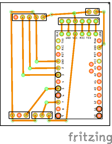
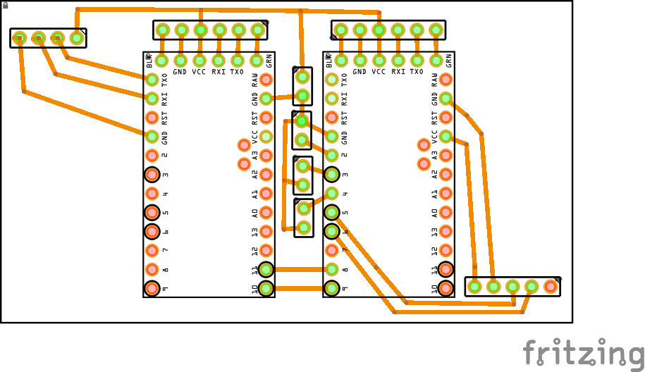
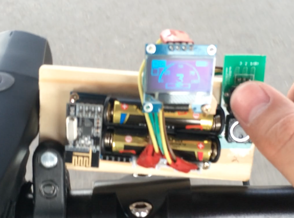
Dashboard PCB version 1.0
05/03/2016 at 21:24 • 0 commentsFirst version of Pedaless Dashboard contain two atmega328 connected between with SoftwareSerial because left atmega328 is in this case GPS module because he reading from GPS and sending that information to right atmega328. Why im using separate atmega328 is because it need around 3 seconds to read GPS signal, and i cannot give 3 seconds delay for transmitting.
Right atmega328 is connected with wireless transceiver, OLED Display, Buttons and analog Throttle. Three buttons are Up / Down / Menu. Up and Down is to setup some settings or use like digital throttle, if you hold two buttons few seconds it will make reset in settings, Menu is for changing screens types.
![]()
-
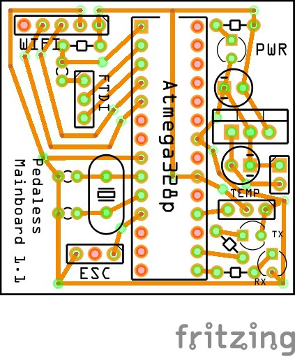
Mainboard version 1.1
04/13/2016 at 20:39 • 0 commentsAfter first prototype was tested, and was pass all tests like hardware and software i was working on new PCB of Mainboard, this version is still one layer PCB because easy for me it was to make it one layer. In pictures you can see PCB design and after soldered. Also in TOP side of PCB i add silk layer.
![]()
In next picutre you can see soldered and tested, all works was fine.
![]()
-
First Prototype Wheel Speed Sensor
04/13/2016 at 09:03 • 0 commentsBecause is good that all modules to be wireless, like speedometer, cadence...etc. I was start testing my prototype to see how all that should be work and implemented. I was need to make new module for that, who will send with NRF24L01 to Dashboard module. In Dashboard module i put new settings screen where you can set your wheel size in inches. And Dashboard module receive signals when wheel is full rotated and then is calculate speed.
![]()
In next video you will see all that how works.
-
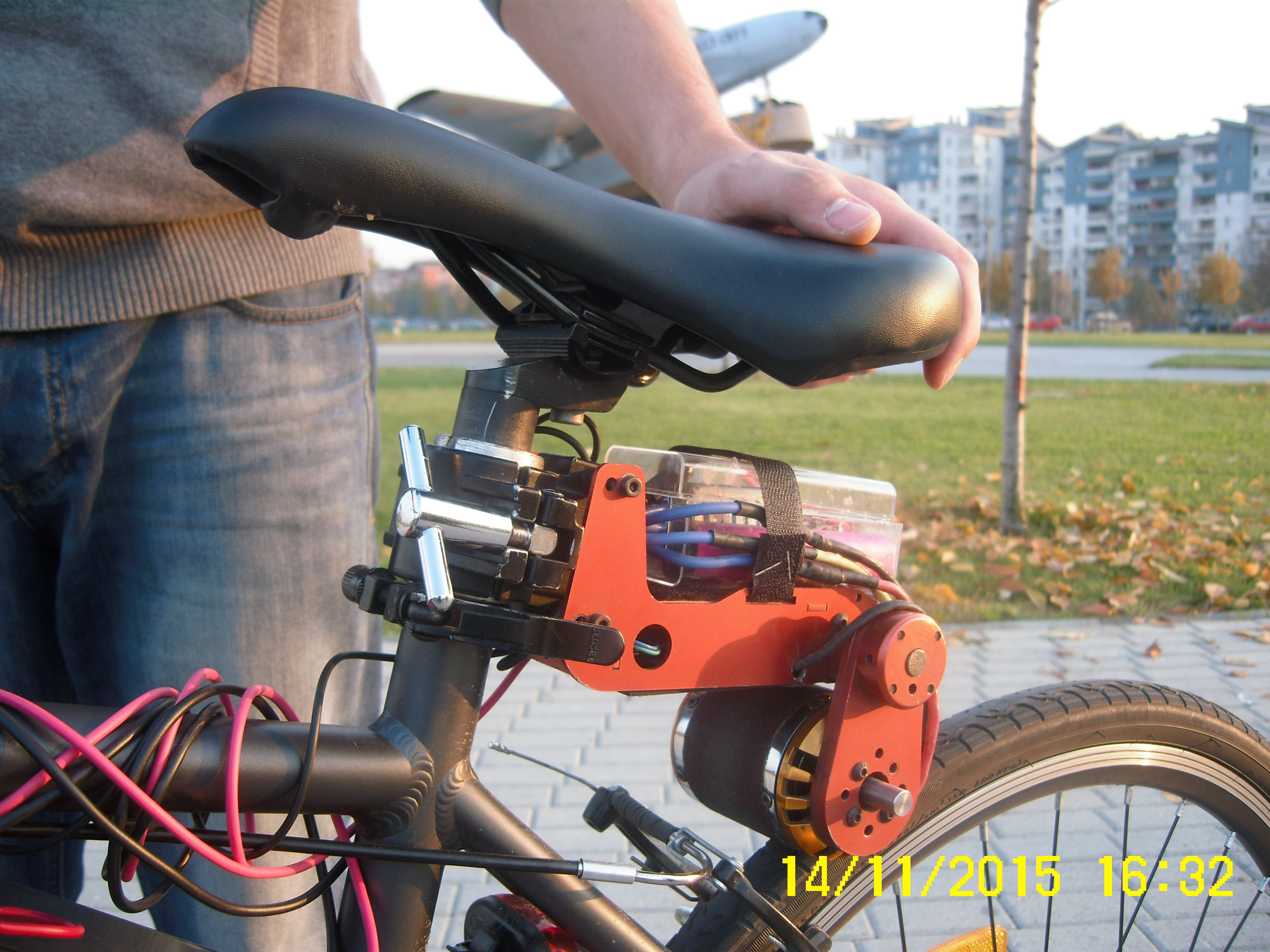
Motor mount 3D Model
04/04/2016 at 20:04 • 0 commentsLet me to explain motor mount. This part is made with strong material, in this case with aluminum. This mount is small and not heavy, and very good fit under bike chair. In body of this mount is space where is added ESC Controller and Arduino. In the end of the mount is brushless motor who falling on wheel. In this 3D model in cap of this body is added also mount for battery.
![]()
Here is after 3D printed model of picture above, inside is enough space for ESC-Controller and PCB.
![]() On top of cap is also mount for battery, in this case is mount for Makita battery, with that case you can easy put and take battery.
On top of cap is also mount for battery, in this case is mount for Makita battery, with that case you can easy put and take battery. ![]()
On image you can see how all that looks good when is included aluminum. Is not same model like on 3D model but same works good.
![]()
-
First Motor PCB Prototype
04/01/2016 at 18:06 • 0 commentsThis PCB prototype I used it to test how the motor will work. In this PCB I have attached sockets for Wireless, Arduino, FTDI and three male pins for power, ESC Controller and Temperature sensor. With the wireless module I'm connecting the front part of Pedaless, I mean the Dashboard. Temperature sensor is attached to the motor and is reading the temperature from there. If the temperature is too high
I'll stop the motor from running in order to prevent it from burning.![]()
-
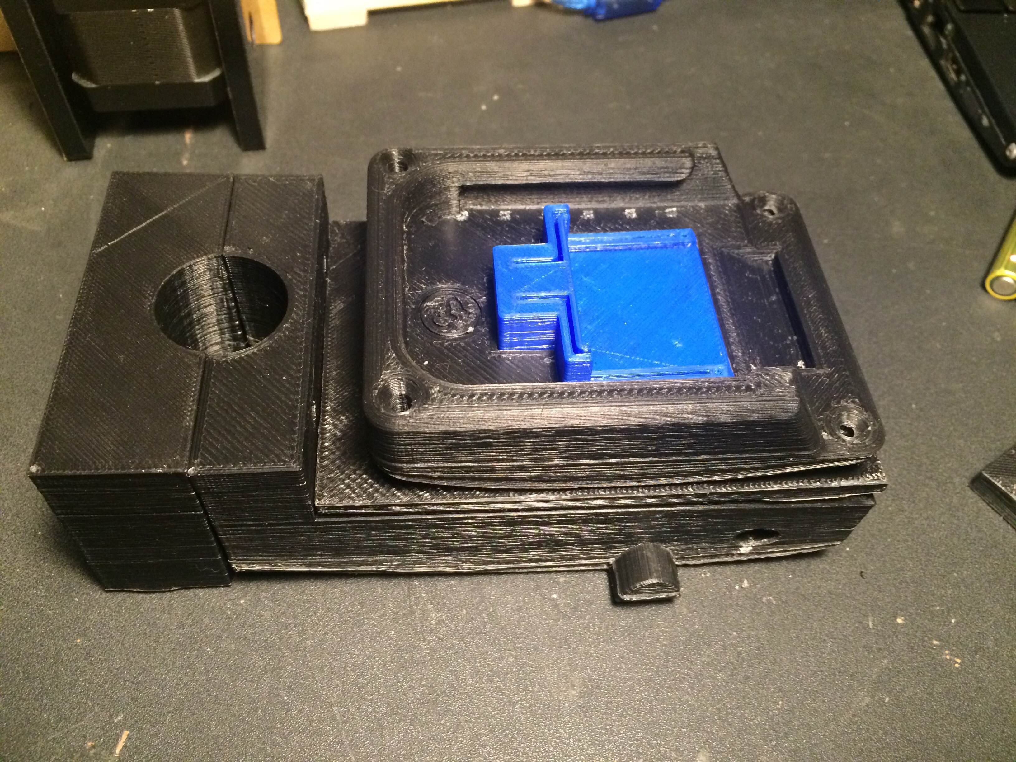
First Dashboard PCB Prototype
04/01/2016 at 17:47 • 0 commentsHere is the first dashboard PCB prototype. In this PCB the sockets were soldered for GPS, Wireless, Buttons, FTDI and Arduinos. The Arduino on the left side is connected with the GPS and that arduino is calculating only the GPS and that information is sent to the other Arduino. The Arduino on the right is connected with Wireless module and buttons. Why I'm using two Arduinos? It's because reading the GPS signal needs about 2 seconds to get good or valid data and because I'm controlling the wireless motor I don't want to have delay that's about 2000ms between each signals. Big delay between motor and dashboard isn't safe and isn't smooth. In this prototype I was using button to increase and decrease throttle of the motor.
![]()
-
Testing overheat sensor for motor
03/31/2016 at 22:53 • 0 commentsImportant module of the motor is the temperature sensor. I added the sensor so that I can control the temperature of the motor. The sensor measures the temperature and if it's above [X] degrees celsius I need to stop the motor to prevent it from overheating. If the motor overheats it can be damaged. So the motor will stop in the same moment when overheating is detected.
![]()
See in next video how all that looks.
-
Testing Prototype
03/31/2016 at 15:20 • 0 commentsHere is the prototype of Pedaless with Nokia LCD display and OLED Display. I have noticed that in day light OLED is much better screen to use and I continued using that display in all future versions. In this prototype the analog throttle is presented and also there is simple design display.
![]()
See in this video how all that looks.
-
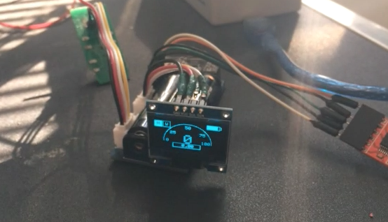
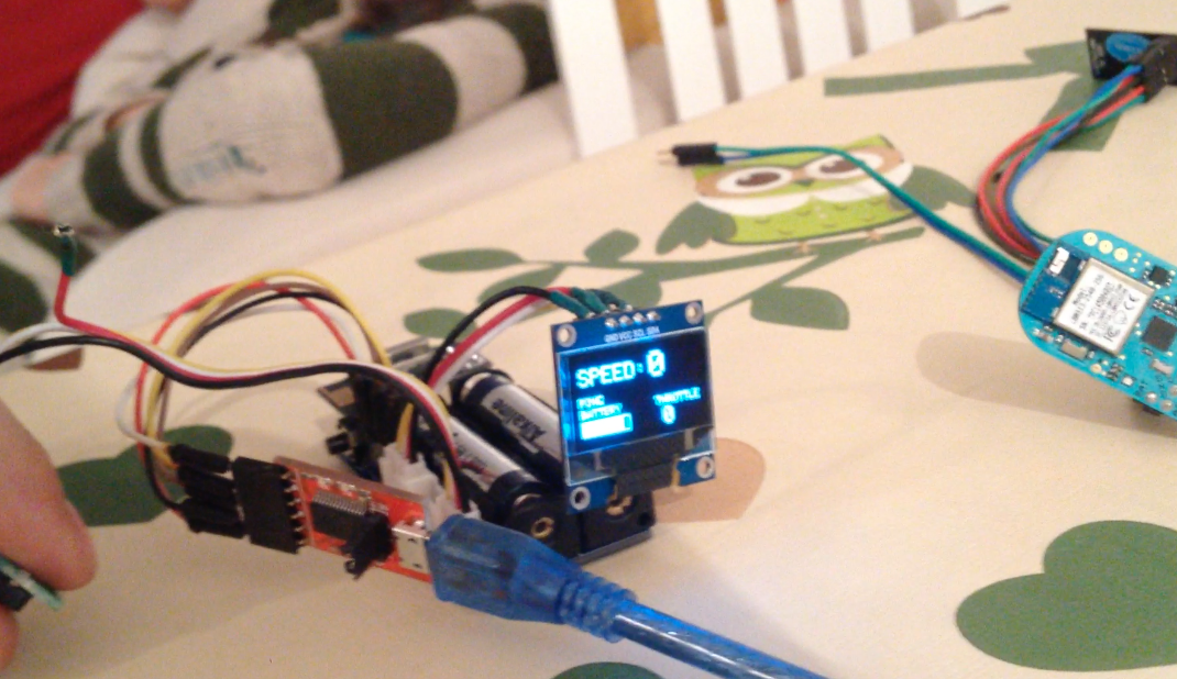
First Dashboard Prototype
03/30/2016 at 14:51 • 0 commentsHere is how the first prototype of the dashboard looks. In the picture you can see the Wireless module, OLED display and buttons. The squares from the top left of the OLED Display present the communication with the Motor an GPS. When they blink it mean that some data is received form GPS/Motor. Top right side of the display is where you can see battery status. In the middle of the screen with big numbers is the speed calculated from GPS. Bellow the speed is the travel distance (odometer), which is calculated from the GPS. Above the speed the power of throttle is presented. It goes from 0% to 100%, all depends on how analog/digital throttle is pressed.
![]()
See how all of that looks in the next video.

 On top of cap is also mount for battery, in this case is mount for Makita battery, with that case you can easy put and take battery.