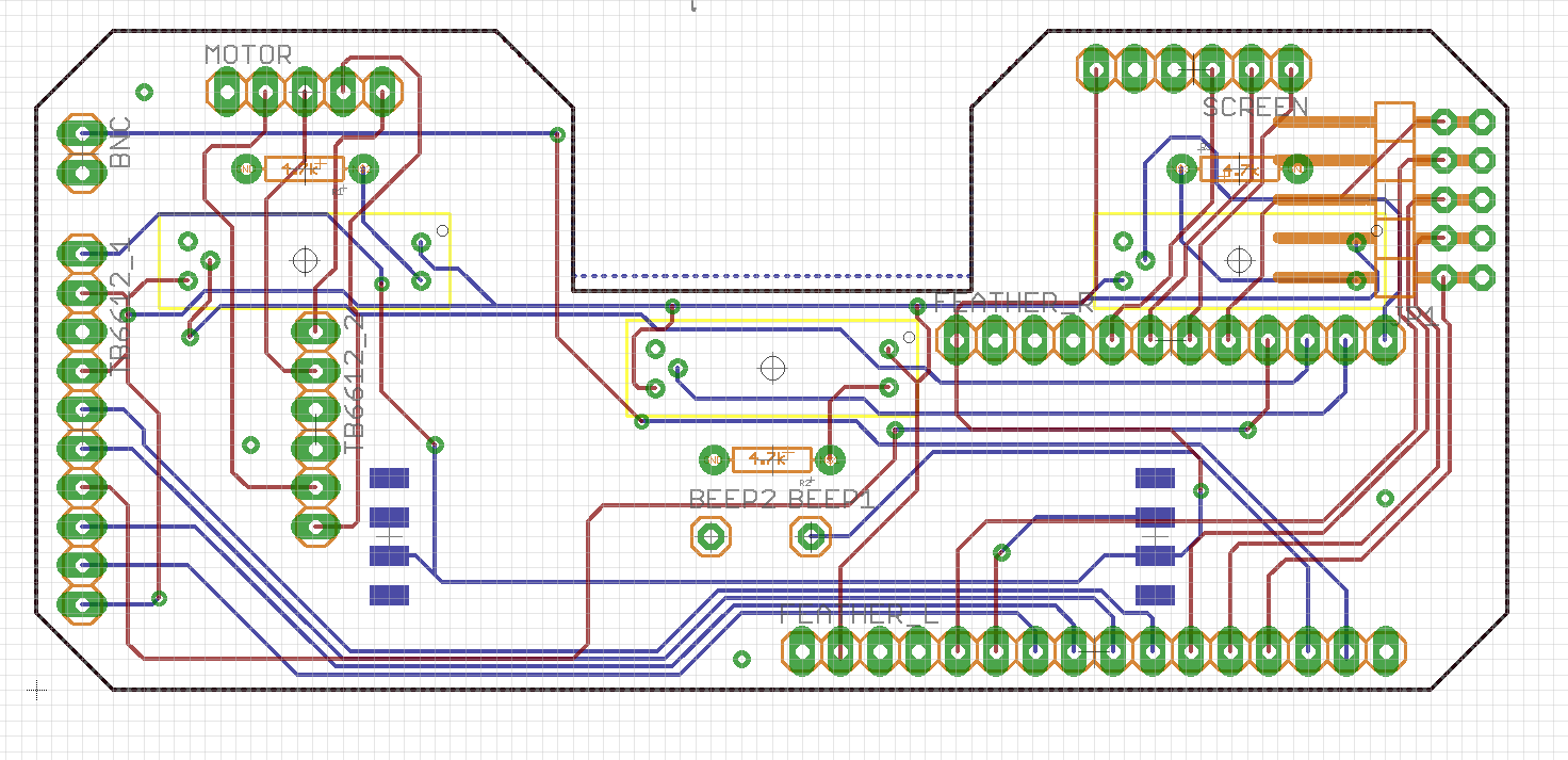
We wrote a simple code that tested the micro-controller's GPIO connections with sensors/actuators. All of the following connections were fine: 3 photo-interrupters, BNC, motor driver, motor headers, screen header, and buzzer. The Neopixel strip was fabricated in the wrong orientation, so I soldered three wires and manually tested it. Consequently, we updated our PCB by carrying out the following:
1) Mirrored all 3 IR sensors and rewired them, in order to operate them on the front side of the board
2) Mirrored Neopixel strip and rewired it in order to solder it to the front side of the board
3) Added 2x5 headers that connect to 4 digital pins, 1 analog pins and of 5 ground pins. These will be utilized for further prototyping/communications with other periphery.
4) Changed the board size and shape in order to improve its fit with already existing FED base.
5) Changed the location of the beeper for a better fit.
The board is ready for fabrication, however, next up: we will be adding a logo to our design!
Discussions
Become a Hackaday.io Member
Create an account to leave a comment. Already have an account? Log In.
This is a great project!
Are you sure? yes | no
This is awesome progress! - thanks for writing a log about it!
Are you sure? yes | no