Close
0%
0%

Simblee App Controlled Outlet

Use the Simblee BLE module and mobile device app to control an electrical outlet.

Similar projects worth following

This project is based off of the SparkFun Controllable Power Outlet Tutorial, but with the added capability of Bluetooth control using the Simblee module. The Simblee is not a typical BLE chip. It has the ability to serve up an app to your mobile device, all programmed in the Arduino IDE. So, for an embedded engineer with no Java or XCode skills, we can still have app integration to our system!

Because the SparkFun project does such a great job at describing how to hook the relay to the outlet, we are going to skip those steps in this write-up. We will focus on two things:

  1. Developing the Simblee application
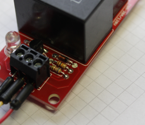
  2. Modifying the Beefcake relay to work well with 3.3V

The Simblee website has all of the documentation available, and I encourage you to check it out. For further Simblee app development, check out this video tutorial series.

relay_single.ino

Source code for Simblee application.

ino - 496.00 bytes - 04/06/2016 at 21:14

Download

  • 1 × Simblee Starter Kit SparkFun DEV-13785
  • 1 × Beefcake Relay Kit SparkFun KIT-11042
  • 1 × 3.3V Regulator SparkFun COM-005626
  • 1 × 680 Ohm Resistor
  • 1 × 10uF Bypass Capacitor

View all 10 components

  • Video Up!

    Nate Bowen04/08/2016 at 20:29 0 comments

    I added a video of the app and outlet working to the Details section.

  • Equations not showing?

    Nate Bowen04/08/2016 at 20:27 0 comments

    I looks like the equations in the build instructions for calculating a resistor value are not showing in some browsers... Not sure what to do about that. I'll give it some time and maybe re-write them in standard text formatting.

View all 2 project logs

  • 1
    Step 1

    Simblee App, Arduino IDE, and Driver Setup

  • 2
    Step 2

    Create Simblee Application

    This is the heart of this project, a mobile device app programmed on the Simblee. The following is the code for creating a user interface to control the Simblee IO pin.


    Include the SimbleeForMobile.h Library

    #include <SimbleeForMobile.h>


    Define Relay Pin

    The pin numbering on the Simblee breakout is 0-6. I recommend using one 2-6 as 0 and 1 are used for the serial port.

    #define    RELAY_PIN    4


    Create a Global ID Variable

    We will need a place to store the ID of the switch object in the user interface. It needs to be of global scope.

    int switchID;

    Setup

    Setup the RELAY_PIN for digital output and start the SimbleeForMobile library using the begin() function, a very important step!

    void setup() { 
        pinMode(RELAY_PIN, OUTPUT); 
        SimbleeForMobile.begin(); 
    } 


    Loop

    The Simblee loop() routine is very different from what we are used to seeing with Arduino programs. The SimbleeForMobile library uses callbacks to execute various parts of the program and the only required code is to call the process() function every time through the loop(). Placing additional code in the loop will not break this, but it may slow down the responsiveness of the app. Especially avoid long delay() calls.

    void loop() {
      SimbleeForMobile.process();
    }


    User Interface

    Now we program the UI. The entire ui() routine is bookended by the beginScreen and endScreen functions. Everything placed between these will be drawn on our screen. This app uses only two elements, text and a switch. The text will simply serve as a label for the switch and the switch will control the IO pin.

    void ui() {
      SimbleeForMobile.beginScreen();
      SimbleeForMobile.drawText(70, 160, "OUTLET", BLACK, 24);
      switchID = SimbleeForMobile.drawSwitch(200, 160);
      SimbleeForMobile.endScreen();
    }
    The parameters for the text are: (x_origin, y_origin, display string, color, size).

    The parameters for the switch are (x_origin, y_origin).

    The call to drawSwitch() returns the ID of that UI element, which is why we created the switchID variable.


    Connect the UI to the IO

    Finally, we can connect the user interface, specifically the switch, to the IO pin on the Simblee. This is achieved with the ui_event function. When the user toggles the switch on the screen, an "event" is triggered and the switchID is passed into this function. An "if" structure determines if the ID of the event that happened is the same as the switchID, and then toggles the IO pin to reflect the value of the switch, 1 or 0.

    void ui_event(event_t &event) {
      if (event.id == switchID) {
        digitalWrite(RELAY_PIN, event.value);
      }
    }

    The source code Arduino file is available in the files section of this project.

  • 3
    Step 3

    Modify and Assemble Beefcake Relay Kit

    The SparkFun Beefcake Relay Kit comes in a ready-to-build kit. You can solder everything in place with the exception of one of the resistors.

    The kit uses a 2N3904 NPN transistor used to take the low-current, 5V control pin voltage and trigger a much higher current for flipping the mechanical relay. The 2N3904 requires 5mA on the base pin to drive the transistor into saturation (fully open) mode. So for a 5V control voltage, the beefcake relay kit places a 1k resistor on the base of the transistor and using Ohm's law,

    The only problem for us is that the Simblee is a 3.3V device. Using the same math as above, we see that the max current that the base of the transistor will get is 3.3mA. This results in very sporadic behavior on the relay. So we need to get that current up by replacing the 1k resistor with something smaller. Back to Ohm's law,

    Something very close to this value will work, a 680 for instance. Don't go too small, though. The Simblee is a very low current device, rated for 5mA per pin and 15mA across all pins at any given time.

    Now go ahead and get the soldering iron hot. Some of those big pins on the relay will take some time to heat up, be patient. Pay close attention to the placement of the diode, too. Direction definitely matters with those.

    This picture shows the 680 ohm resistor farthest from the relay body.

View all 7 instructions

Enjoy this project?

Share

Discussions

Similar Projects

Does this project spark your interest?

Become a member to follow this project and never miss any updates