 Yann Guidon / YGDES
In our latest coverage of this thorny subject (Crystal oscillator) our anti-hero met many difficulties that left him hopeless, after a dozen of failed attempts.
SHAOS tipped him about several circuits, such as these ones:

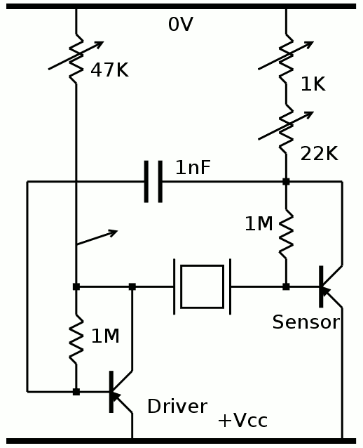
But this one (found there) seemed the most interesting:
It evokes the one that was already successful but upon closer inspection, it's actually a 2-stages, capacitively-coupled, high gain amplifier. It is straight-forward to reverse for PNP so I did it. From the past experiences, I replaced R2 and R4 by 47K trimmers, while R1/R3 are dumb biasing resistors, anything goes. C2 is kept at 1nF. (note: see the comments, where Alexander mentions that this value is also influential)
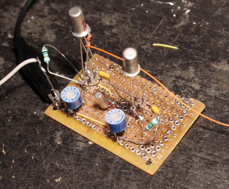
I equiped it first with a pair of GC117c (see the bottom of Testing Germanium transistors (2nd part)) because they have higher gain and lower leakage. I set the trimmers to 10K each and powered on.
The crystal oscillated immediately !
I played with all the parameters (suply voltages, trimmers, transistor types...)
- The type of transistor matters. Like, a lot. A 2N2907 (gain: 225) works great, the GC117 is good and even the lowest gains (a pair of 36) works nicely. However the 2N396 of my collection, or the MP13A with a gain of 40, or a MP26 work like wet fireworks. I could use a MP13A as at the "sensor" side but it would accept to work with a higher voltage, a GC117c for driving, and different trimmer settings.
- The supply voltage also plays an important role. For this clock I target Vmin=4V, and if possible less because I'll try to regulate the voltage and drop is expected. The GC117 and 2N2907 work down to 2V, though the resistors must be tuned a bit.
- The 2 trimmers are really important.
- R2 is the "gain" of the amplifier, controlling the amplitude and bias. When it's correctly set, the output is a clean sine that has maximal amplitude. The value varies with the transistor and power supply voltage... Max value: 47K
- R4 tunes the impedance and certainly the quartz frequency. I could increase the sinewave's amplitude when R4 is set to a very precise position, so the crystal resontates at its rated frequency. Max value: 22K, probably in series with a 1K trimmer too. Also changes with the transistor type, so this is a required feature, a standard value will not be enough.
EDIT: further experiments proved me wrong, as Alexander suggested in the comments. Forget about the 1K trimmer. Say welcome to a variable C2...
I have a better confidence that it can drive larger crystals, with different ratings and larger energy requirements. The output should be obtained on the collector of VT1 and I will add some weak capacitive coupling to a buffer transistor.
Compared to the previous working circuit, which was totally symmetrical, this one separates the sensing and the amplification, which provides a better flexibility for tuning. There is one more part (capacitor) but this topology also oscillates with more amplitude, up to the full GND-Vcc range. This amplitude can be reduced by increasing R2, which saves some power. The driving signal voltage doesn't need to be full-range anyway, and this is used as output too, which only needs to trigger the Vbe of a cascaded PNP (Vbe=0.2V) thus only 0.5V amplitude is necessary. The higher amplitude is suitable for the CMOS version as well. It's good to be able to tune one parameter without affecting the other too much.
The type of the transistors is important and the "dumb" MP types (rated around 1MHz) are not suitable. Higher-frequency-capable transistors are needed.
I also understand why some people are so in love with the "germanium sound" : some of these parts are just "lazy" and are rather bandwidth-limited. But here, this does not work.
And now, I can sleep happily with the feeling that I have acquired more wisdom, and I've found a reliable solution for one module of the clock.
Edit: thanks for the comments, guys ! You really help me to make sense of all of this :-)
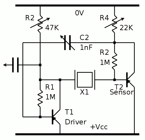
Updated schematic :
Discussions
Become a Hackaday.io Member
Create an account to leave a comment. Already have an account? Log In.
MP13 and similar are medium-frequency transistors. Note that transition frequency * doesn't mean point where it suddenly stops working, though it is point where it stops amplifying after slow roll-off. Decreasing of gain starts at much lower frequency. What more, it is dependant on collector current. Those MXxx do have Ft declared as 0,25 or 0,5MHz and high internal capacities, meaning that even at 32kHz it doesn't have enough gain to oscillate - and it has low Hfe anyway, to start with. Transistors in here are P416, with "respectable" 40MHz Ft, so it has really a lot of gain margin at 32kHz.
GC117 do have somehow higher Hfe and transition frequency 1MHz, so it is a bit more suitable than MPxx. Seems like this is enough for the oscillator.
Anyway, great work, I like this kind of experimenting.
* https://en.wikipedia.org/wiki/Gain%E2%80%93bandwidth_product#Transistors
Are you sure? yes | no
Oh crappy transparent gifs.
Are you sure? yes | no
Thanks for the enlightening comments, I had overlooked the issue you mentioned... and I love this kind of experimenting too ;-) It keeps me humble and on the edge...
I'm adding a version with white background to the log (link already in the log)
Are you sure? yes | no
П416Б (P416B) is even better - 80 MHz and h21e=90...200
http://www.eandc.ru/catalog/detail.php?ID=12833
Just bought a bunch on ebay ;)
Are you sure? yes | no
isn't that ... "modern" ? :-D
Hopefully, the rest will work well enough with older types.
Are you sure? yes | no
I try to work with "only necessary" characteristics and I understand better the minimal parameters... Fortunately the system requires "high performance" only at a few key spots. 2/3 of the circuits are considered slow and should need only "slow" parts working in saturated mode.
Are you sure? yes | no
Great! Also that article mentioned that circuit keeps functioning with wide range of component values and with voltages from 1.5 to 12V. Also it's saying that capacitor C2 could be used to adjust the frequency.
Are you sure? yes | no
Thanks for this other hint !
A variable capacitor is more expensive than a variable resistor and frequency is a R×C story so I keep it simple with the tuning resistor. But it's always good to know !
This also means... If C is reduced, like 100pF, the resistance may be increased as much and lower the power draw...
DAaaaaammmn.... I must experiment again ! I don"t thank you ;-)
Are you sure? yes | no
I retract what I wrote: R2 and R4 don't affect the frequency. As you suggested, I'll have to tweak C2 :-/
Are you sure? yes | no