 SHAOS
SHAOSSo going further with replicating circuits from old Russian magazine (1983):
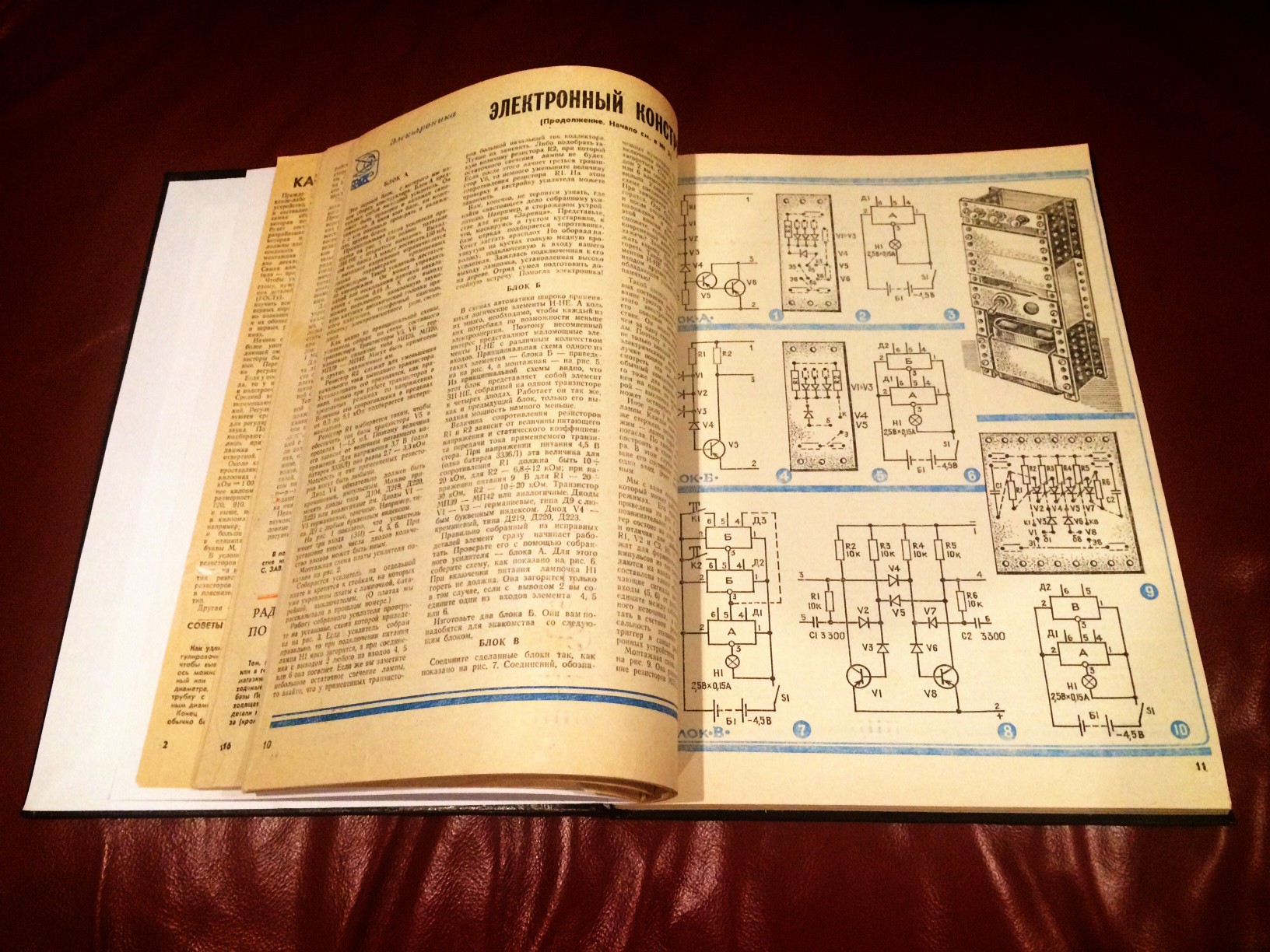
Now using 2 NANDs (version with LEDs) I built trigger (as on Fig.7 above):
Then added couple resistors and couple capacitors to get universal trigger (as on Fig.8)
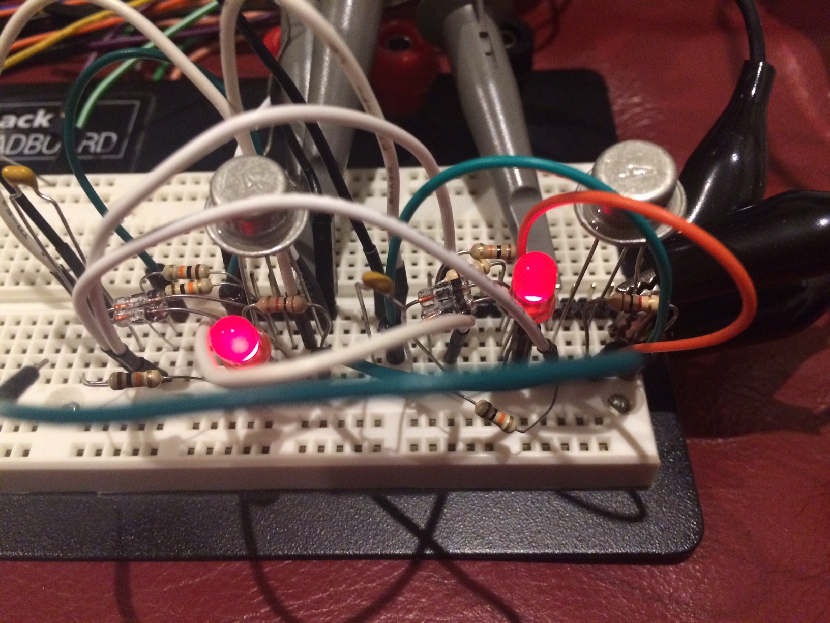
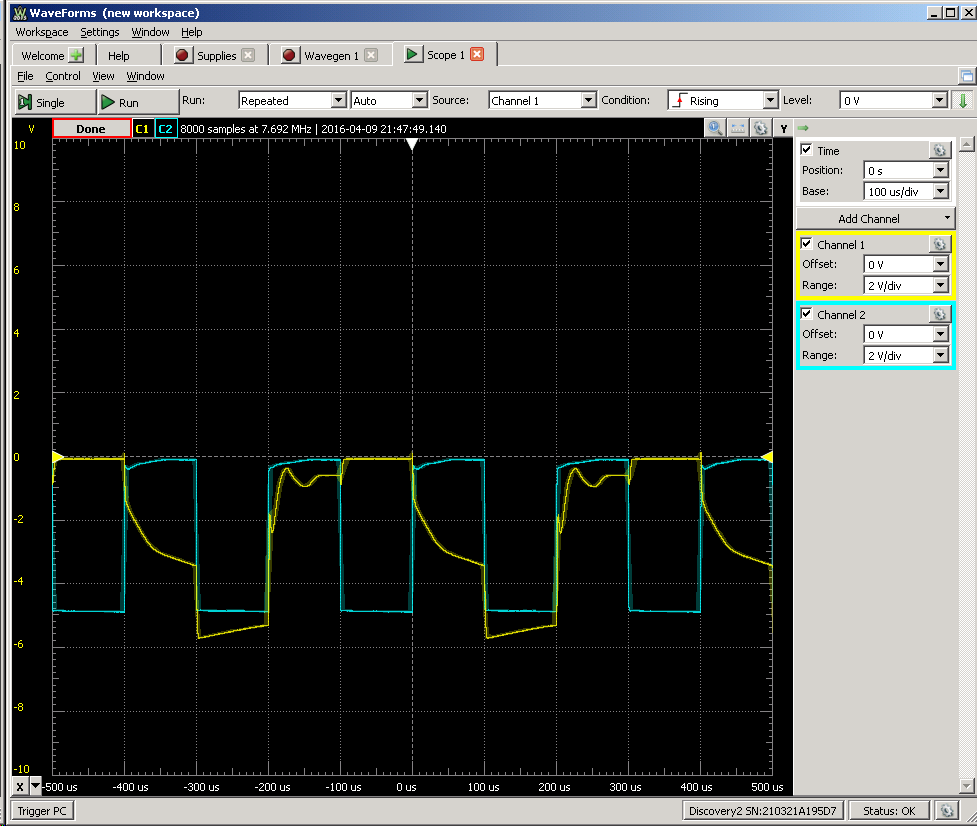
That can toggle state if inputs 5 and 6 connected together - 100 Hz:
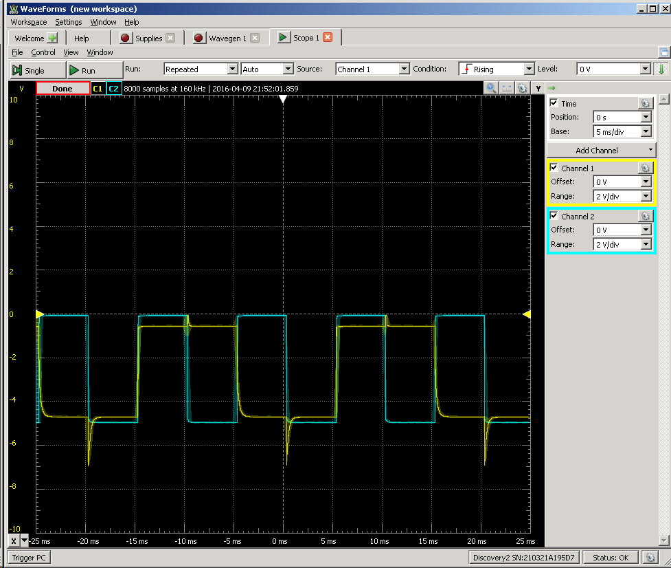
1 kHz:
5 kHz:
It looks like this is a limit (and trick with "speed-up" capacitor doesn't help) - probably I should play with values of resistors and capacitors...
UPDATE: Everything above was for C1=C2=10000 pF, now I'm trying 470 pF
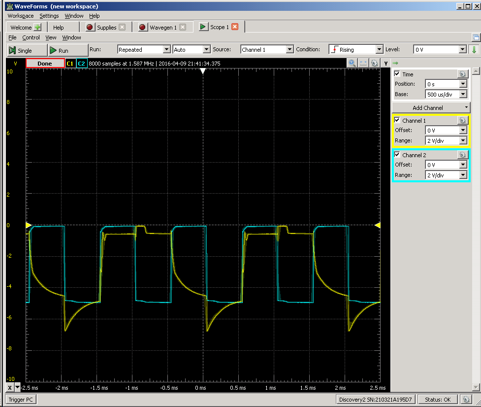
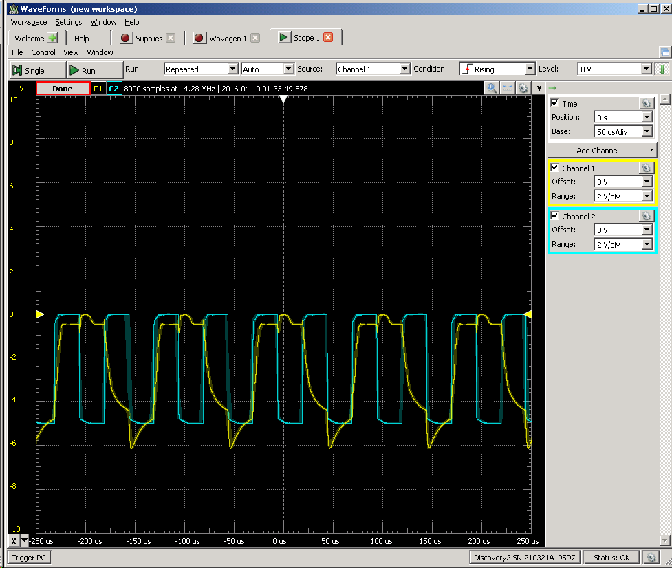
10 kHz:
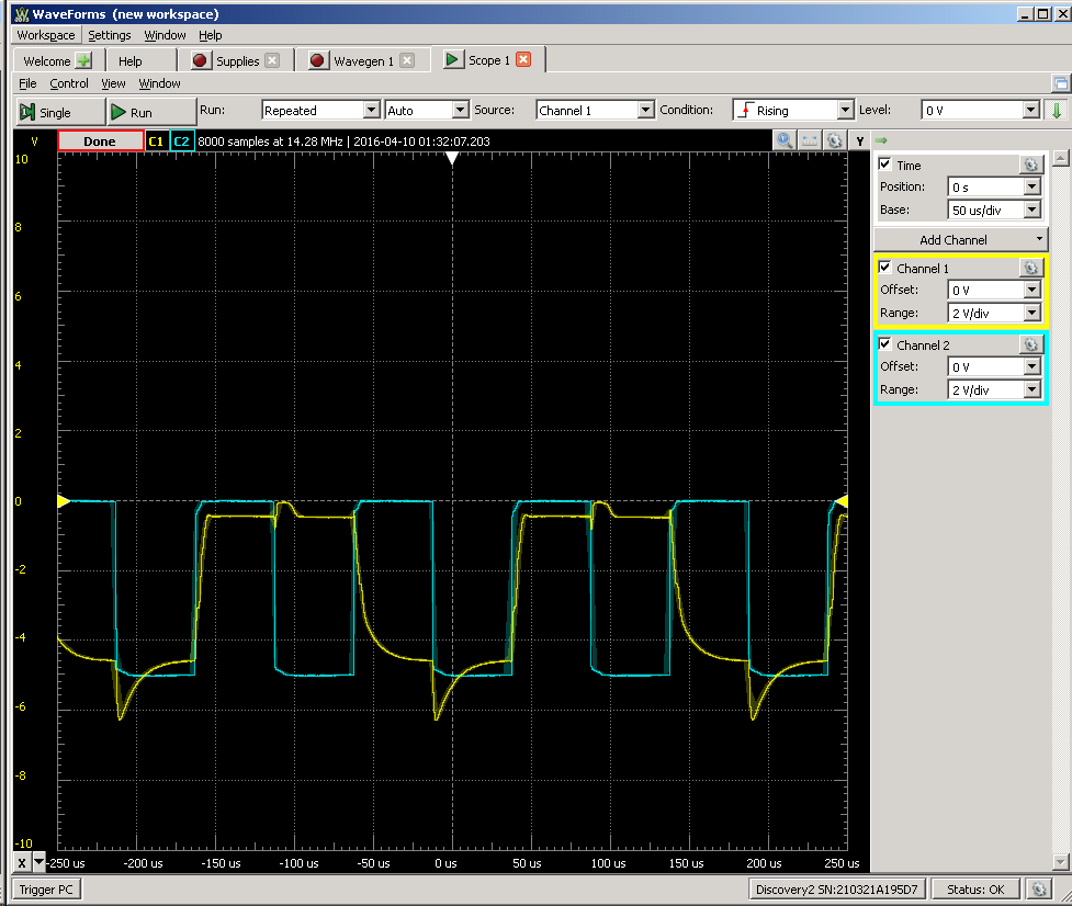
20 kHz:
On 50 kHz it doesn't look good...
UPDATE (04/10/2016): Today 50 kHz looks much healthier - I don't know why :)

But if go higher output shape is quickly shifted up (to the ground) - probably because of natural limit that caused by latency about 5 us...
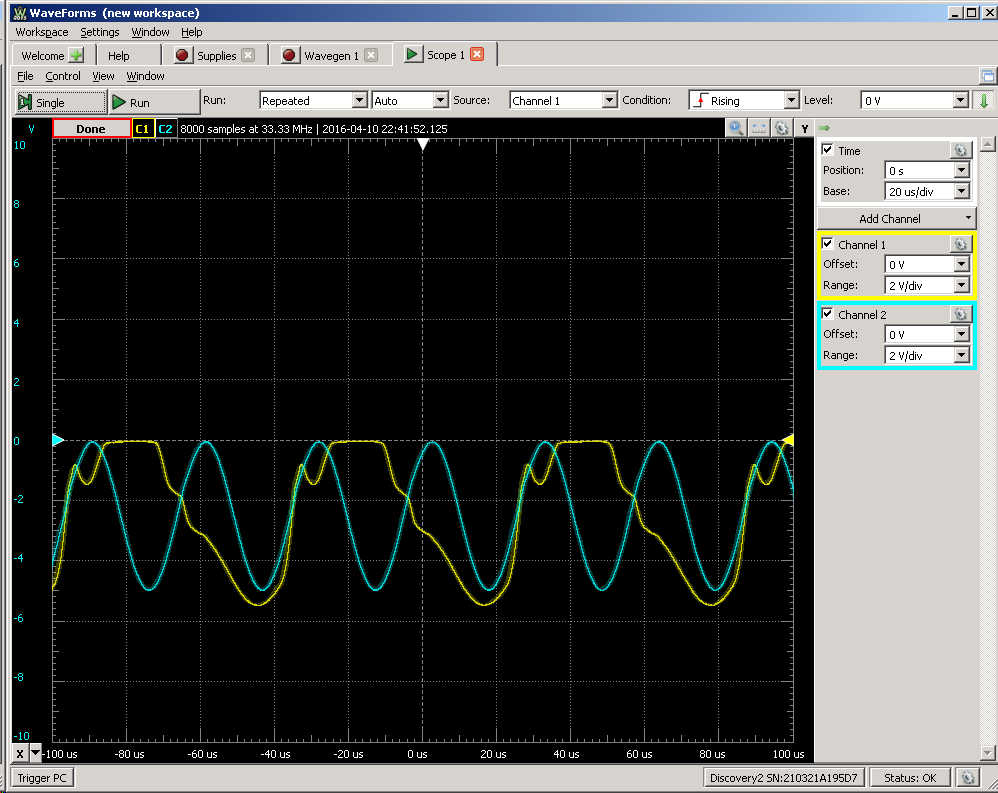
P.S. Almost forgot - 32 kHz sine signal :)
P.P.S. Redrawn schematics:
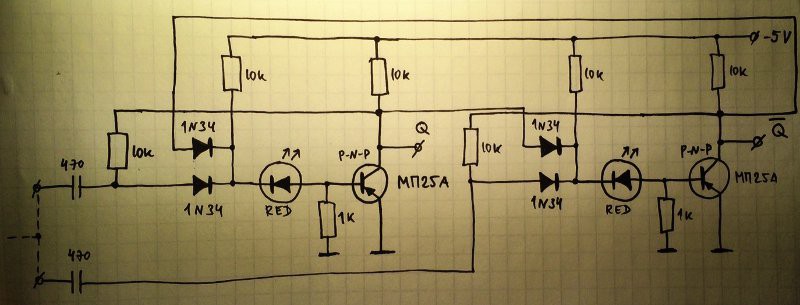
Note: Wires that goes above diodes are NOT connected to diodes' cathodes as may mistakenly appear in your mind (check closely - there are no dots there)
Discussions
Become a Hackaday.io Member
Create an account to leave a comment. Already have an account? Log In.
I see : the bases are tied with 1K (that's quite tough), and there is a LED in series ...
Are you sure? yes | no
LED is used instead of silicone diode that shifts threshold - in some of my previous logs here I also tried Zener there and it also worked ;)
https://hackaday.io/project/10698-clockwork-germanium/log/35378-2nd-approach
Are you sure? yes | no
and no parallel capacitor ? The 1K on the base draws quite some current...
Are you sure? yes | no
Thanks for the drawing :-) BTW you should also have a reset input, but that's just one more diode.
Are you sure? yes | no
Nice touch with the 32KHz signal :-)
Are you sure? yes | no
I assume for a few first stages of binary divider we need to use faster transistors - the same as in oscillator. let's spare the lazy MPxx for later stages. we will need a lots of them
Are you sure? yes | no
That's exactly my idea :-) That's why I'm stocking less lazy parts too.
Are you sure? yes | no
What's the value of the resistors and capacitors ? Can you redraw the whole diagram ? Arent's some diodes superfluous ? I should try the DCTL version as used in the CDC6600...
Are you sure? yes | no
All resistors are 10K as on the picture 8. For capacitors instead of 3300 pF I took what I had on hands - 10000 (marked 103)
Are you sure? yes | no
Faster gates use lower resistor values, AFAIK, so this might explain some speed limits... Can you try with 1K and see how much faster it runs ?
Are you sure? yes | no
I tried 470 pF - works up to 20 kHz
Are you sure? yes | no
Hey it is "almost there" :-) Could you try with a sinewave input ? That's what the 18KHz generator will provide...
Are you sure? yes | no
Well, I realised something: trace shapes are an esthetical thing, since Ge commutes at about 0.2V so as long as the circuit reaches even 1V it's ok. Now I wonder how your diodes influence this...
Are you sure? yes | no
I'm not sure what do you mean exactly :)
Are you sure? yes | no
Well... I'll experiment :-)
Are you sure? yes | no
It's starting to work ! I'll have to analyse the schematic and try with other kinds of transistors...
Are you sure? yes | no