 Yann Guidon / YGDES
The seller provided the following picture but even after receiving the crystals in tubes, many questions remain.

First, is it series or parallel resonance ?
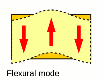
Then what type of cut is it ? https://en.wikipedia.org/wiki/Crystal_oscillator#Crystal_cuts has many choices but many are vague. I can already filter with the frequency range (when provided). The shape of the crystal cut and the plating/electrodes reduce the possibilities further : the oscillation mode is obviously "bending", like a vibraphone bar. From https://upload.wikimedia.org/wikipedia/commons/8/8b/Crystal_modes_multilingual.svg:
The possible cuts are
- X
- H
- XY (though this fabulous article would not agree)
- NT
The electrodes prevent most harmonic/overtone vibration modes because the "middle" electrode (2/3) short-circuits opposite charges. So the frequency and waveform/shape would be quite pure and stable.
The "passport" that @[skaarj] translated (in the comments) mentions -80°C to +80°C operating conditions, which are another hint for the cut. It seems to be symmetric around 0°C, which is unusual. Finding (or measuring???) the temperature response curve would help even more. Does anyone have a climate testing chamber ?
Initially I feared that the frequency stability would be poor but it might be the reverse, this will have to be measured and I suppose that the germanium leakage will be the greatest source of variations. I'll probably have to find/imagine a balanced/symmetrical oscillator circuit using matched pairs...
One more hint would be the internal connexions. Some electrodes are connected to structural elements, hence have higher capacitance. Some output wires are connected in parallel with the structure, as well.
http://www.ieee-uffc.org/main/history-marrison.asp contains a very interesting hint at fig.8 :
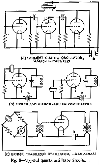
(Wait: what is this "bridge-stabilised oscillator" ? I have to look that up
Update: ok, no, it works in series resistance resonance but I don't know if the tubes are rated for series or parallel mode)
I suppose this 4-electrodes crystal works in a different cut/mode but from there, my latest guesses are confirmed and I suppose the following:
- short electrode (1/3) for driving the crystal (with enough drive, but smaller surface if compensated by high gain circuits)
- long electrode (2/3) for collecting the charges and providing feedback
- opposite side electrode (full length, 3/3) is grounded (otherwise, relative to what point do we measure the charges ?)
Or maybe swap 2/3 and 3/3. I'll have to test that... After all there are only 6 combinations :-D
Measurements:
- The quartz bar is 30mm long
- contacts are at 7.5mm from each end
- The short electrode is 8.3mm long
Things add up nicely :-) 7.5×4=30mm, so the oscillation is in bending mode, perpendicular to the electrode platings. Contacts are placed at the point of least motion, to prevent attenuation, at 1/4 and 3/4.
The puzzling part is the 8.3mm of the short electrode, I don't know why this length. The ±3.6 ratio does not correspond to an obvious mathematical relation. It's close to 3.3 and has misled me but maybe the measurement is not precise enough.
Discussions
Become a Hackaday.io Member
Create an account to leave a comment. Already have an account? Log In.