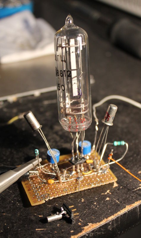
In the previous episode, Reverse-engineering vintage quartz resonators, we had a lot of questions and a few hints. The best way to be sure was to try them.
I took the previous board (see Crystal Oscillator (Germanium Edition)) and removed the 32768Hz Xtal. Instead I put a 3-pins socket, with ground in the middle. I put the 2 crystals (in succession) on a connector and tested them.
The wristwatch crystal needs quite specific parameters to work correctly.
The russian crystal just worked, oscillating immediately with the parameter of the tiny crystal. Oscillation persists even with both trimmers cranked up to the max (47K Ohms) at 1.5V (though startup was slow). But even then, it just worked, using low gain transistors (hFE=37).
I feared that operating it would be difficult, like requiring more driving energy because of the larger size (higher motional inertia) and other factors. But the tube just "rings". No I can't hear it but it picked up the oscillations much better than the tiny tuning fork, requiring less energy.
I suppose that the lower frequency also contributes to this sensitivity, since the transistors are not ultra-high performance. So the rough MP13B might work as well. A recent planar transistor will fly. I should still investigate the MOSFETs...
One surprising result was that it works better when the "large electrode" is on the driving side, leaving the small electrode to the sensing side. I haven't tried all the 6 combinations/permutations of the pins yet, though, but this would be a very interesting experminent. But first I need a tool/measure to measure the gain, other than the time taken by the oscillations to reach full range.
Whatever the result, my bet on this tube has been a clear win, on every account. It costs more than a dumb wristwatch crystal but it requires less driving energy so it's energy-saving. It looks much better, might have a better temperature stability and it's pretty unique...
We'll see soon how it behaves and how it is tuned.
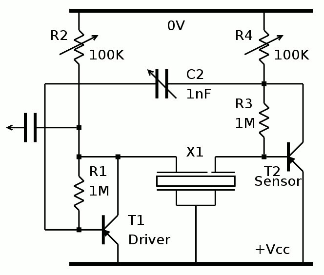
By popular demand, here is the updated schematic :

R2 and R4 have been increased because the signal saturates fast, and saturation is not good. Actually, the best is to have a small sine, less distorsion and better accuracy.
Due to the higher sensitivity of the crystal, R1 and R3 can be increased as well.
C2 must be evaluated. I don't have the means to calibrate this frequency yet (my #ScoPower gizmo is fixed to 32768Hz). I'm waiting for my Rb source and a DDS.
I will have to evaluate the effect of leakage, thus of temperature-induced drift.
To compensate power supply voltage drift, I'll probably add a micropower voltage regulator. No Zener diode because of the tempco and the worse regulation ratio. This is why I try to make it work at a lower voltage than the rest.
 Yann Guidon / YGDES
Discussions
Become a Hackaday.io Member
Create an account to leave a comment. Already have an account? Log In.
There are 4-port crystals sold today as monolithic filters. See:
https://www.electronics-notes.com/articles/electronic_components/quartz-crystal-xtal/monolithic-crystal-filter.php
Are you sure? yes | no
Hehehehe I should try this topology with MOSFETs and the large crystal :-) That would be for #Yet Another (Discrete) Clock !
Are you sure? yes | no
Great news! So what did you connect where?
Are you sure? yes | no
Maybe it was not clear enough, so I will rewrite it here clearly :-)
* transistor collector to medium sized electrode
* Vcc to the long electrode
* base of the other transistor to the small (1/3) electrode.
I tried the reverse (medium and long swapped), it worked but with less gain (hence more energy so less interesting)
There remains 4 other combinations to try :-D
If you want to try, start from the schematic you gave me and that worked the last time with germanium.
Are you sure? yes | no
What is "large/long electrode" - this part I didn't get in either of explanations :)
I see that you solder some wires together - could you please take a
picture from the side to see clearly what was connected with what?
Are you sure? yes | no
OK, I'll make pictures and a diagram
Are you sure? yes | no
so those 2 connected together points are supposed to be grounded?...
Are you sure? yes | no
"suppose", i don't know, but i guesstimated it from an old schematic.
It just happens to work. And the electrode's sizes matter in unexpected ways so you are encouraged to experiment :-)
Are you sure? yes | no
The "guess" came from a picture found at http://www.ieee-uffc.org/main/history-marrison.asp
The top schematic obviously uses a 4-electrodes crystal but the electrodes seem to have the same size. This seems to have been refined since then, the asymetry provides a noticeable gain (try in reverse to compare).
I'm very curious about the bridge-stabilised oscillator, but it seems to work only for series resonance, which has a different frequency than parallel resonance and much better Q. How could these 2 parameters be combined ? I've never used a bridge topology before... (except for full diode bridges of course)
Are you sure? yes | no
Actually I don't see asymmetry - all contacts look perfectly symmetrical
Are you sure? yes | no
The contacts are perfectly symmetrical. However the electrodes, the plating on the crystal, has a clear ridge near one of the contacts. That's what i call the "short electrode".
Are you sure? yes | no
ok, I see now - it's a gray gap in the surface
Are you sure? yes | no