 Yann Guidon / YGDES
The last log (More bistables) found some explanations of the weird flip-flop schematic I initially found.
Today, a comment by RSMilward on hackaday.io brought a new light to the mystery !
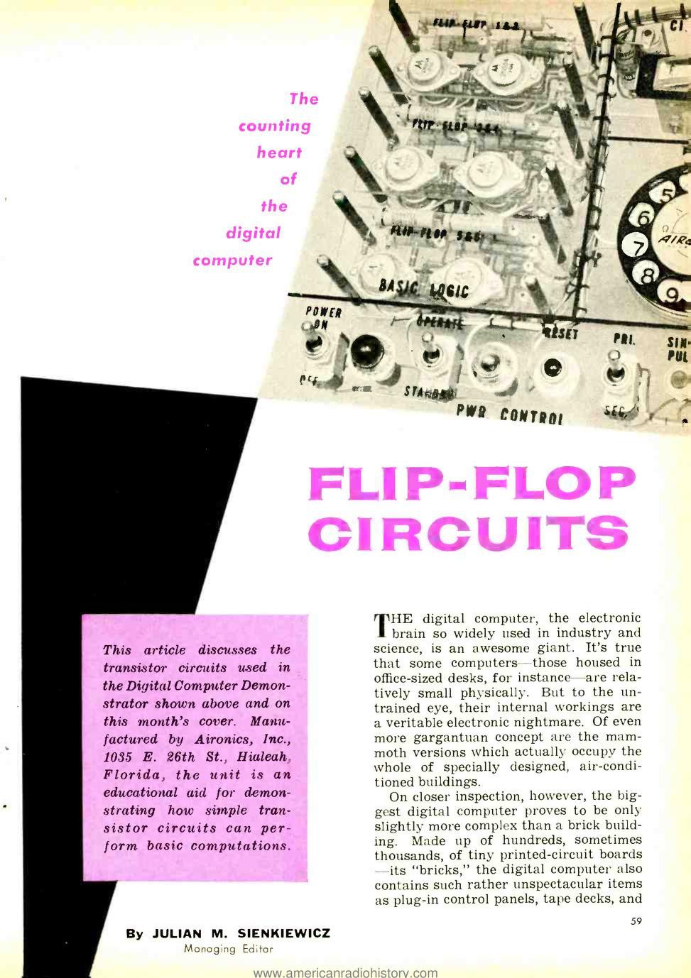
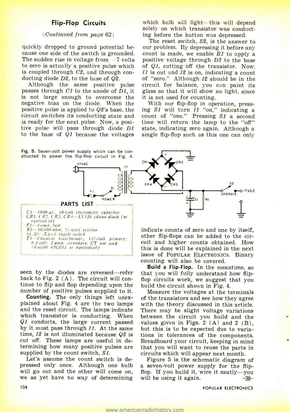
This one comes from an even earlier publication (1961) in Popular Electronics, hosted on archive.org :
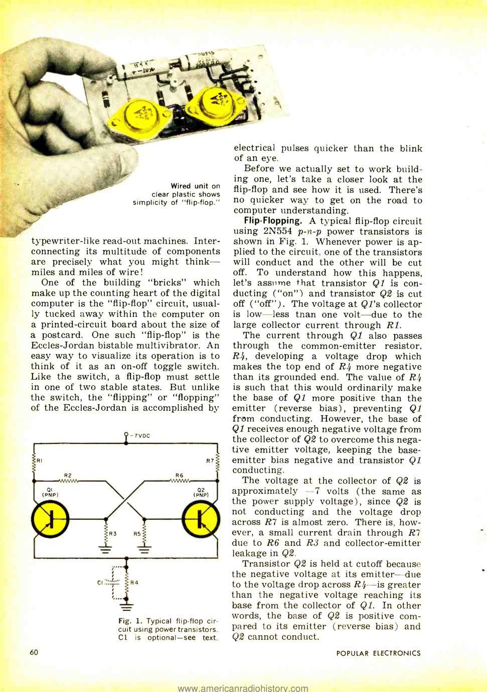
From the experience with the 10TFF and looking at vintage circuits, I realise something about edge-triggered flip-flops with only 2 transistors. In the 10TFF, a temporary value is held as a charge on one transistor's gate. This principle is found in the 2BJT circuits with actual capacitors, which are "protected" from the previous stage by a series resistors.
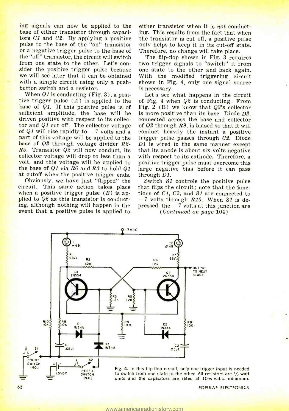
This resistor is critical for the speed and power consumption. The RC constant must be adapted to the system's speed. That's where the 2BJT circuits reach their limit... For the "slow" parts of the clock, this is not a problem and this will save quite a lot of germanium parts, but there are quite a few diodes and other passive parts.
Discussions
Become a Hackaday.io Member
Create an account to leave a comment. Already have an account? Log In.
OMG - I grew up in Hialeah for my first 38 years and could take you to that address. I was 5 in 1961 :-) And PnP's make good Nands :-)
Are you sure? yes | no
That era... what on earth with having negative rails at the top?!
Are you sure? yes | no
same reaction...
those diagrams need to be redrawn !
Are you sure? yes | no
No, all other diagrams need to be redrawn with negative rail on top!
Are you sure? yes | no
muahahahaha
Are you sure? yes | no
Logic made with PNP power transistors!
Now, I've seen everything.
(I guess they're still smaller than tubes)
Are you sure? yes | no
I have NO IDEA why they chose these. Maybe there was a cheap surplus/stock somewhere...
Are you sure? yes | no
Unlip them and you'll get logic circuit that can be activated by strong ambient light. :P
Are you sure? yes | no
That solves the clock distribution problem - just get a strong strobe lamp.
Are you sure? yes | no
@Ted Yapo now we're speaking :-P
Are you sure? yes | no
Well, the power transistors are here to switch incandescent lamps. Yet there is still some power margin left.
Are you sure? yes | no
I guess that being that there were no Leds you had to use regular lamps with higher current draw. I wish I could go back to those days :-)
Are you sure? yes | no
Go back ? why ?
Are you sure? yes | no
I grew up with vacuum tubes so
Are you sure? yes | no
I grew up with vacuum tubes so still a bit old school :-) I am in my comfort zone with older stuff ;-)
Are you sure? yes | no
I see you're trying new things with your cardboard project, neat ;-)
Are you sure? yes | no