 Yann Guidon / YGDES
Remember the last logs : the goal is to use as few transistors as possible to send a string of consecutive non-overlapping pulses to several pass-gates. Here the design uses NPN as primary type but it will be reversed later because PNP are the majority type in Germanium and NPN are getting hard to get...
The last log Towards a smaller shift register has explored several methods but nothing satisfying yet.
Today I tried 2 new tricks :
- Feed the output back to the input
- use diodes to separate the stages and hopefully prevent the simulator to amplify spurious activity.
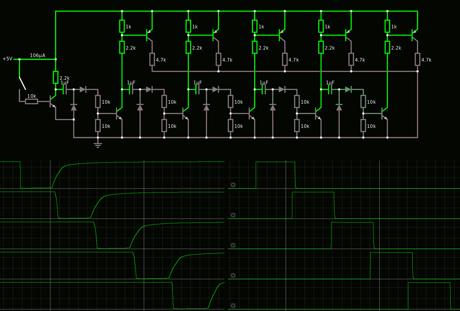
The first result is there :
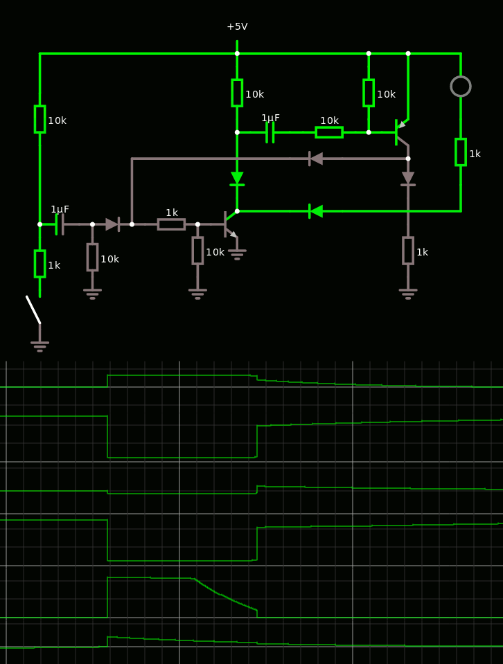
The down and up edges are pretty clean though the output has a sort of slant after the first half of the pulse.
There is one great advantage here compared to the previous versions : the cell is triggered by a positive-going pulse, and the idle state does not draw any current. This saves power and reduces drift, compared to the almost-always-on earlier version.
The "cost" is 1P 1N 2C 3D 6R and can still be tuned.
However when a resistor is replaced by a diode (to make a sort of charge pump) the result is even more interesting because 2 phases appear (source) :
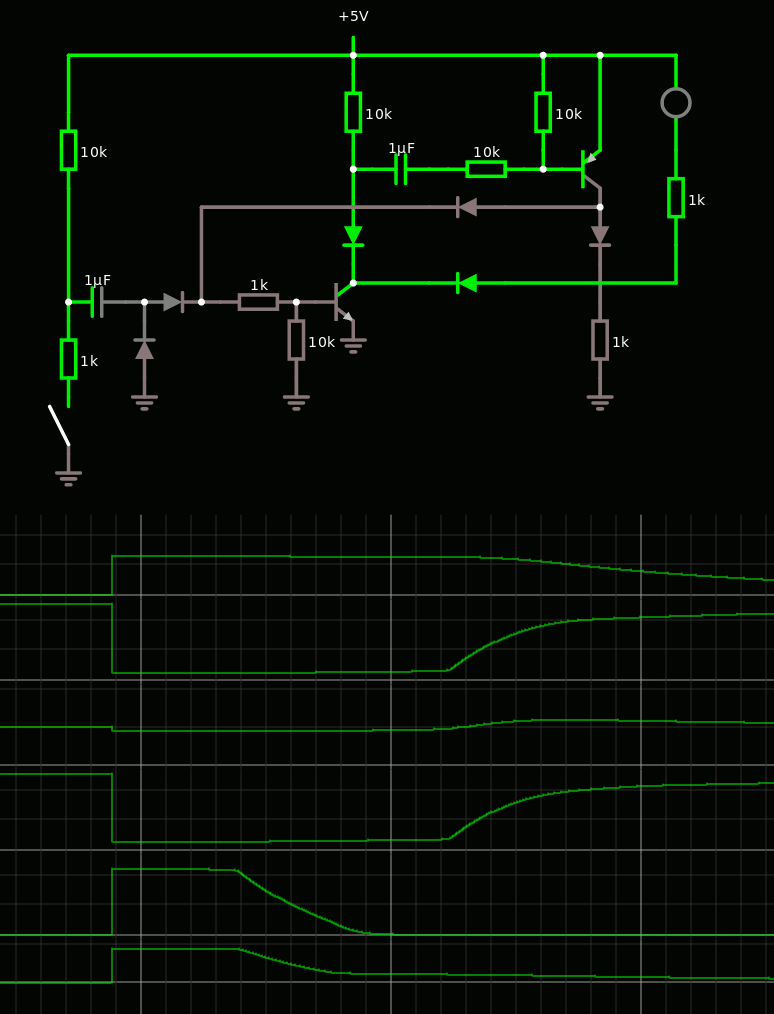
The trailing edges are not as sharp but they are now significantly separated, there is a short pulse (going to the pass gate) and then the output to the next stage happens.
Apparently the sharpness of the trailing edges are not a critical parameter : (source)
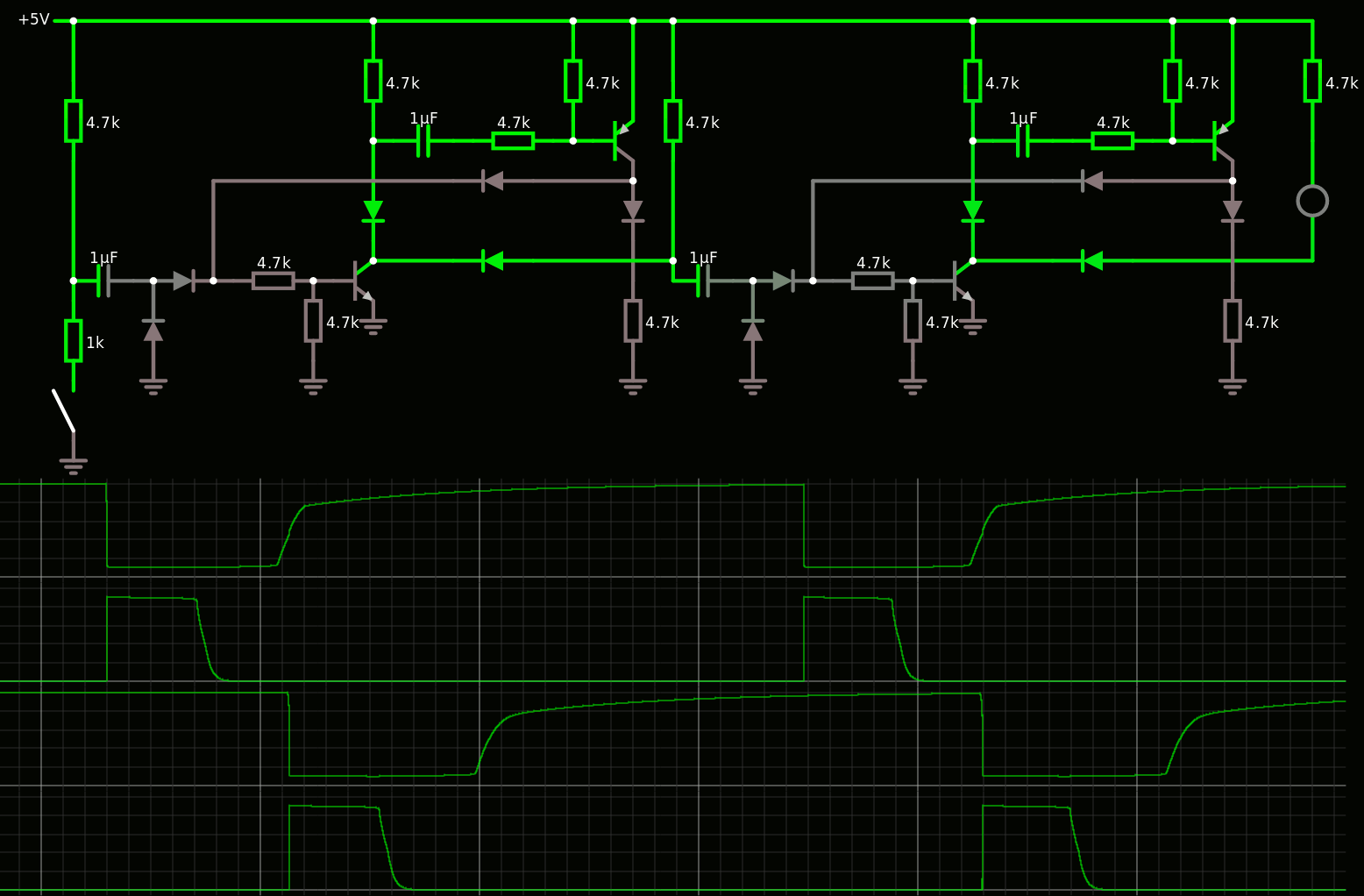
I changed all values to 4K7 and it seems to help a bit.
I wonder if/how this circuit could be simplified...
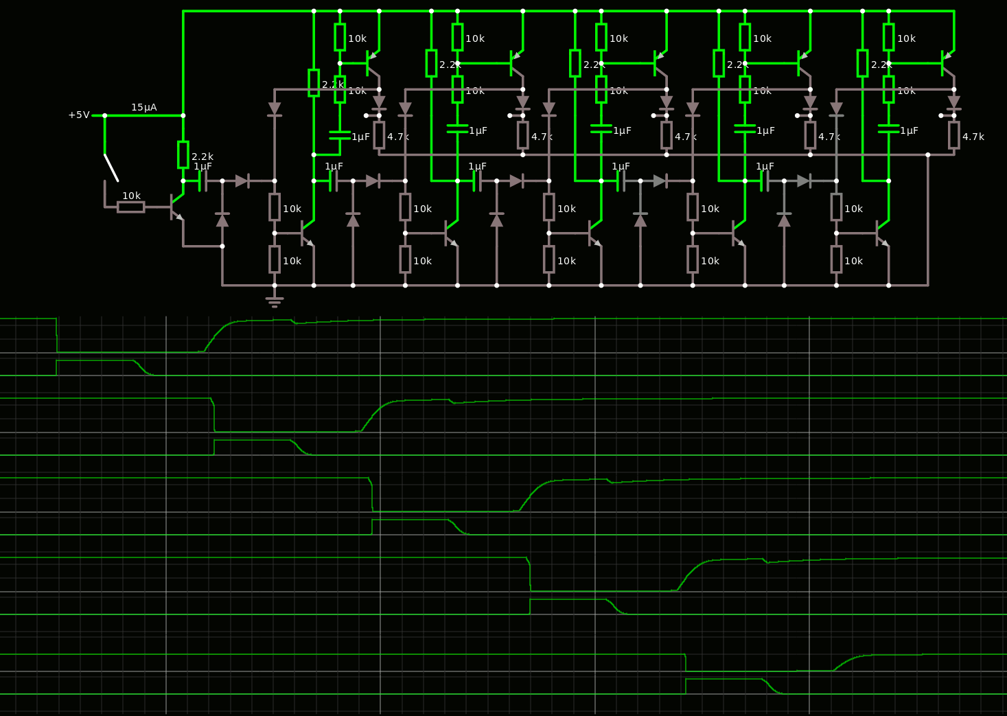
Trying to simplify the circuit and going back to the "first principles", I get this sequencer :
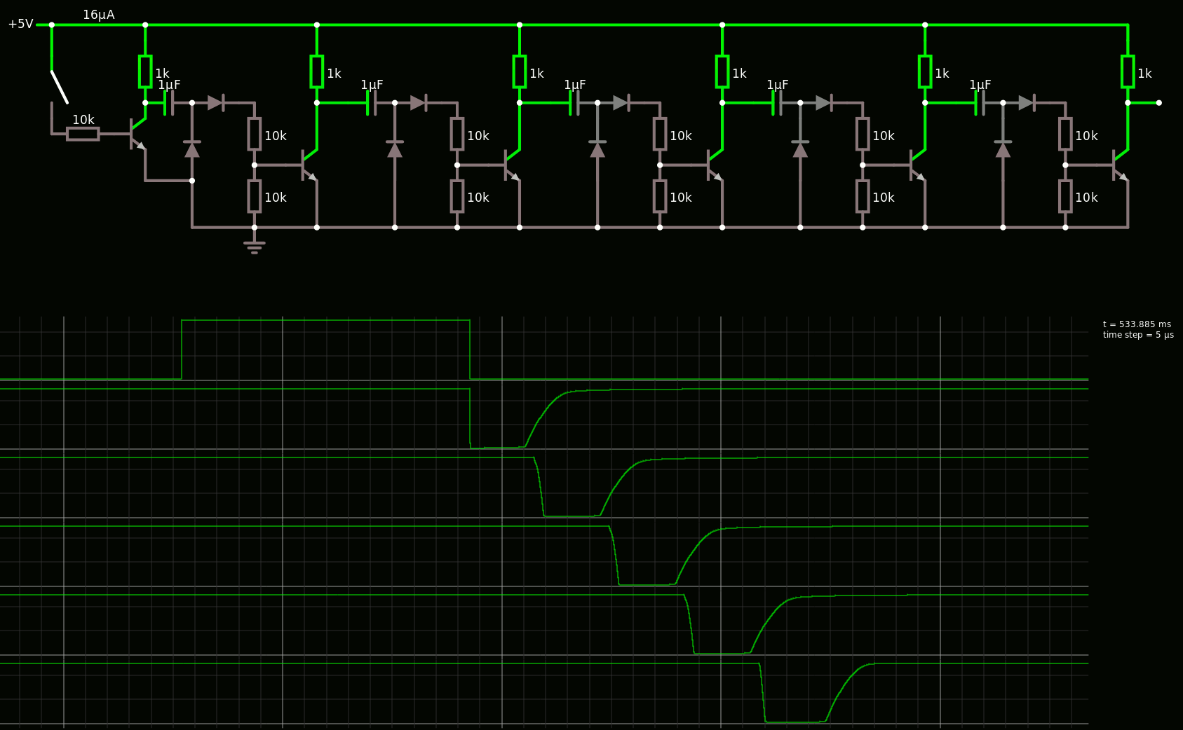
Falstad did some really strange things with the "charge-pump-like" diodes and capacitor, like creating one pulse of the low AND the high going input pulses, so I had to restart from a clean empty page and compare with real circuits (just to be sure).
The wave shape of this 5x sequencer doesn't look different from the previous one but it is way cleaner than the early attempts. Now I doubt that the feedback and more diodes are required.
Note that the capacitor "pull-up" resistor must be significantly smaller than the transistor's base resistors because otherwise, the "going-high" front will make a resistor divider equivalent through the capacitor, which reduces the effective voltage range on the divider network and reduce the pulse time.
The power is kept rather low, with about 5-8mA during activity, and mostly no current when idle. Only one cell is active at a time, except during transitions. The current is only dependent on the above-mentioned pull-up resistor that charges the capacitor before the up-going front when the transistor is released. That can easily be halved with a higher resistor (2K2) and/or a lower supply voltage.
Adding a simple complementary common-emitter cell creates overlapping pulses :
Adding a simple RC cell shortens the output pulse. The shape is not as sharp as I'd like but it's a minimal working circuit :

This saves quite a lot of diodes, compared to the circuit at the top of this page. And the feedback is not even used.
So it's working, the required power is reasonable, the pulses do not overlap and I can control the pulse widths with the corresponding RC constant...
I tried to remove the diodes but the sequencer would be much less reliable. This output drivers seem to work without diodes but the trailing edge is not clean.
However, adding one diode as feedback brings some advantage :
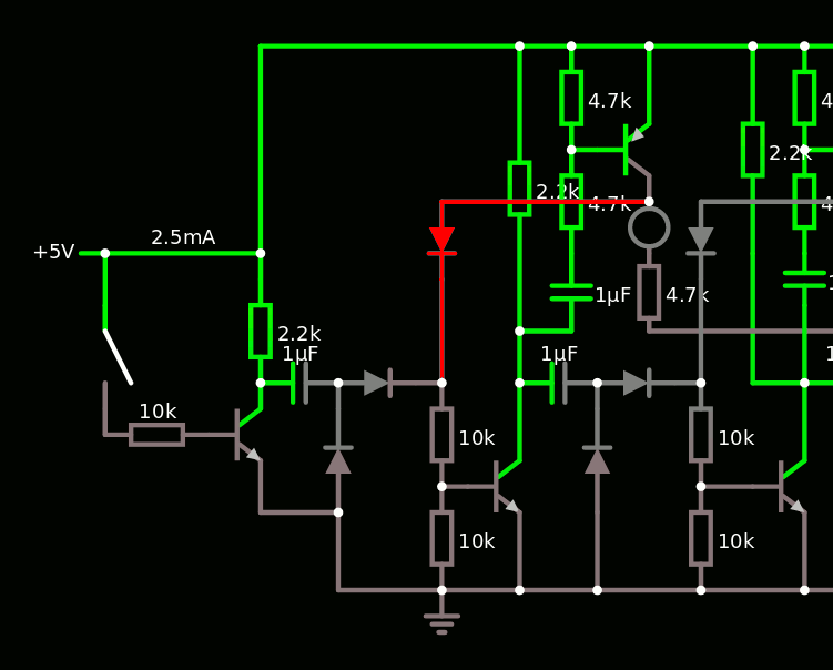
It prevents the capacitor from discharging, until the PNP's output goes to 2 diode drops. The rising edge is delayed until a safer output level is reached. This prevents overlapping conduction for the rest of the circuit, AND both base resistors can now have the same value (they are 2×10K or 2×4K7 but now this difference is not required).
This new version also adds a series diode to the output buffer, to ensure that the voltage really drops low enough. However this might not be really necessary because the pass transistor has a Vbe drop as well. The output is cleaner anyway :
Now each bit slice has 2 transistors, 3(4?) diodes, 5 resistors...
Discussions
Become a Hackaday.io Member
Create an account to leave a comment. Already have an account? Log In.