 Elia
EliaI have received the Rev, A boards today and they look good as all the OSHpark boards do. The shipping for OSHpark boards seems to have got significantly faster, it took the boards only one week to arrive.
The image below shows a fully assembled board riding piggy back on one of my RTL-SDR dongles. I have yet to clean off the flux residue from the board. I currently remove flux residue using Q-tips and isopropyl alcohol but that leaves white streaks on the board. Any suggestions on what might work better?
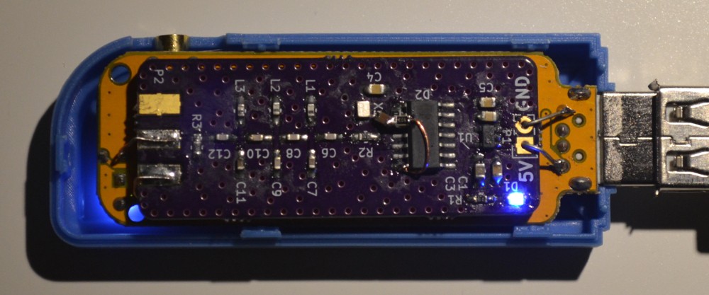
As you can see I did have to add a bit of a bodge to the circuit. The problem was that the output of the TCXO is only about 1V peak-to-peak, which is not enough to trigger the clock input of the D flip flop. The bodge adds two 10k biasing resistors to the clock input of the 74AC74 and the TCXO signal is AC coupled to the clock input via a 4.7uF capacitor.
I had actually thought of this when doing the schematic, but somehow I was under the impression that the output amplitude of the TCXO would be high enough after looking at the datasheet. I probably misinterpreted the amplitude given in the datasheet.
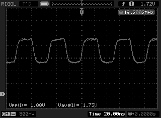
The image below shows the waveform on the clock input of the 74AC74 at 19.2MHz, you can see the 1.7V offset and the 1Vpp TCXO signal:
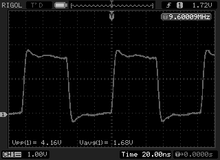
The output of the 74AC74 looks a little less pretty, with some overshoot on the rising and falling edges. I couldn't get rid of that even probing with the little springy grounding tip:
And finally the 28.8MHz output after the band pass filter:
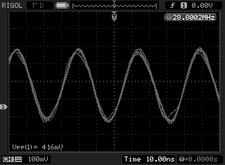
The output signal has quite a bit of jitter and you can clearly see that there are still higher order harmonics contained in the signal. It still kind of looks like a triangle wave with rounded corners rather than a pure sine, but it seems to work fine at least after a quick test.
The dongle is also fine with the 400mVpp input signal, which according to the R820T datasheet is in the specified range of 150mVpp to 3.3Vpp.
That's all for now. In the future I have to check the temperature stability versus an unmodified dongle and make some pretty graphs. Before I do that however, I need to finish my GPSDO project, so I have a stable reference time base for my frequency counter.
Discussions
Become a Hackaday.io Member
Create an account to leave a comment. Already have an account? Log In.
BBQ lighter fluid/paint thinner (mineral spirits) seems to work well for cleaning off flux. They do take a while to evaporate. When cleaning with an old tooth brush I put (old) paper under the PCB and try to only brush in one direction - towards the outside of the PCB.
Are you sure? yes | no
Thanks, I'll get myself some paint thinner (turpentine substitute) and try to get that stuff off.
I am always worried about ESD when using a toothbrush, probably will end up getting a brush with those conductive bristles.
Are you sure? yes | no