 rawe
raweA quartz clock epoxy blob contains the following logic (more or less):
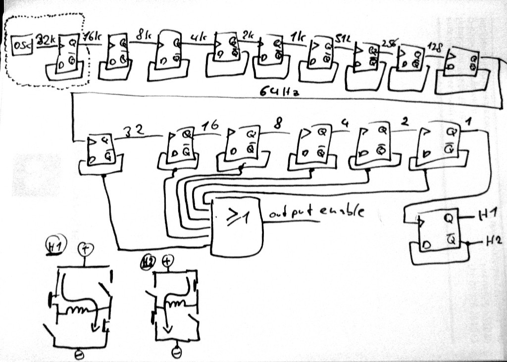
We got an oscillator (with support from an external quartz crystal), a whole bunch of frequency division stages and at the end a H-bridge which drives the electromagnet. A half evolution of the electromagnet moves the second pointer 1 second forward. All this bases on the exact time input from the oscillator/clock crystal which is 32768Hz +/- 0,00...% . The electromagnet is driven in short pulses to reduce power consumption (see "output enable" signal in figure above).
If such a clockwork needs conversion from 12 to 24 hours, the easiest way to achieve this is to reduce the input clock frequency to 50%.
It is not as easy as to just put another clock divider stage in there. As all this is buried on a chip in a black epoxy blob it is not possible to access this logic structure without huge effort.
Due to the way quartz oscillators are built, it is possible to just feed an external frequency into one of the pins and let the circuit run on this frequency.
See the following sketch for a detailed standard-logic-ic replacement of the dotted area in the figure above:
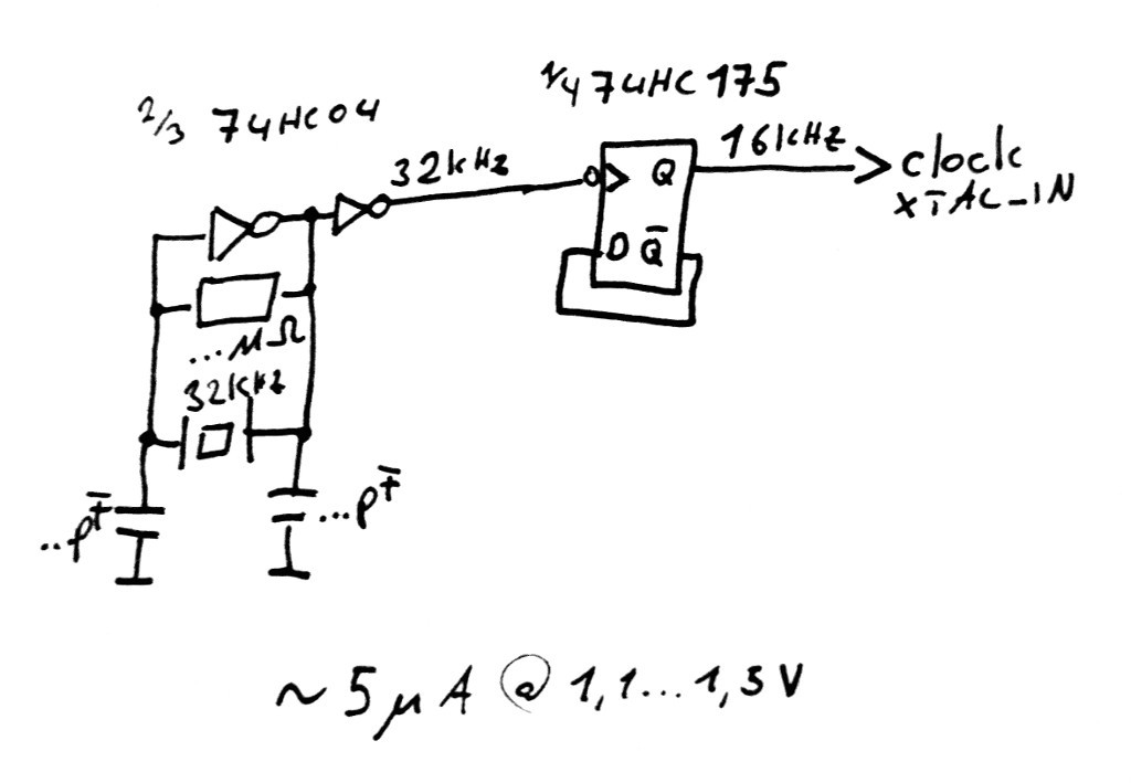
If the quartz is left out on the inverter IC, it is possible to just feed a signal in on inverter input.
My initial plan was to re-create this circuit, but replace the 74HC175 flipflop with an ne555 non-retriggerable monoflop with a monoflop-time of a tiny bit over one period of the 32kHz input. As the ne555 is just overkill for this application I decided to spend a few cents on a bunch of 75HC175 D-Flipflop from old stock (datecode 1988...) and go that route - sorry, the ne555 was just for the search hits :P.
The following screenshot was taken from the circuit above (yellow: current consumption in uAmps, blue: circuit output / 16kHz)

As the inverter and flipflop are cmos based, the current spikes occur at the same time as the logic gates switch. High spikes show the flipflop and inverter switch at the same time, low spikes show the inverter only. The average current consumption boils down to approx 5uA.
Connected with the clock and zoomed out the following picture appears (yellow: current in uA, peak mode enabled to fight aliasing):
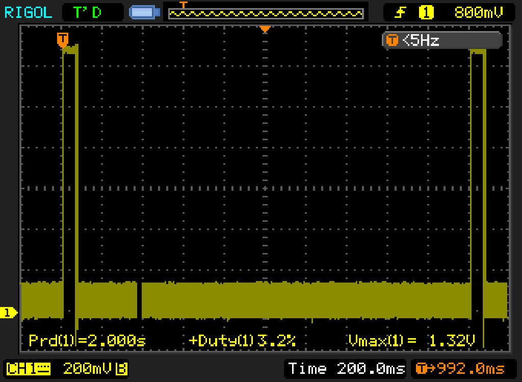
The bold line on the bottom shows the logic ICs switching. The big pulses at 2 sec period (clipped - ucurrent runs on 3V battery) show the drive magnet spin.
The circuit is built in 3d prototype construction technique for now, a flat perfboard design will follow.
Discussions
Become a Hackaday.io Member
Create an account to leave a comment. Already have an account? Log In.