Nixie
Nixie-
Case closed. (spincoater II)
08/06/2018 at 09:25 • 0 commentsWith the excellent result achieved with the improvised spin coater, it becamse sacrilegous to leave it at that, dangling wires and crappy mounting.
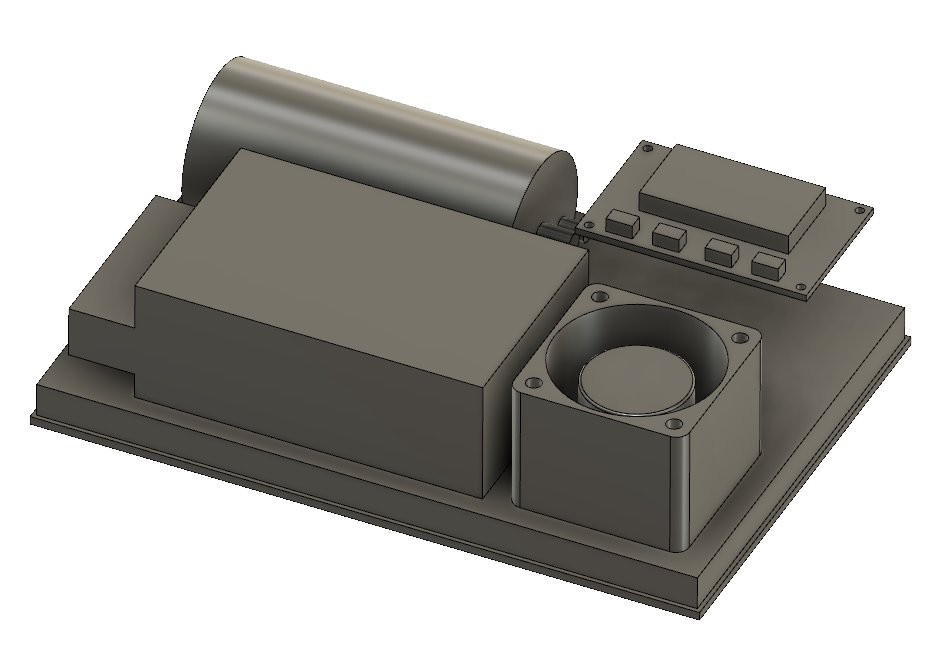
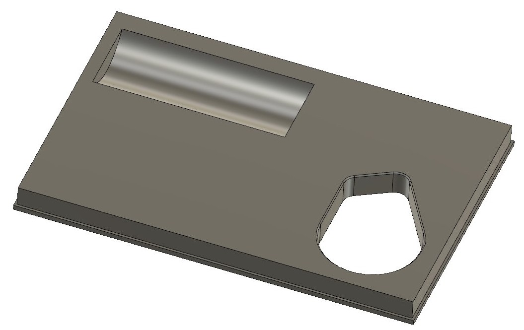
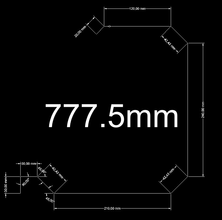
Thus, I set myself on the task of building a nice enclosure. First I quickly modelled everything in Fusion:
![]()
A thick base was added, so it's weight could act as vibration dampening. It would have a recess for the vacuum pump, as it was 8mm thicker than the power supply, and also a hole for the vacuum adapter for the motor to fit in. Resuming, I wanted the thinnest possible unit.
![]()
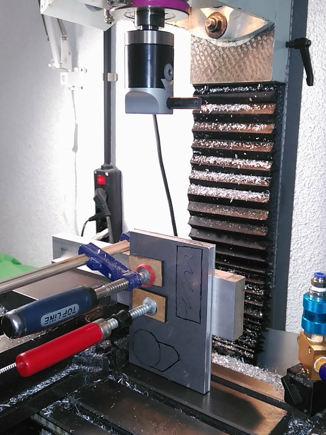
With that, I set up workshop to machine, cut and weld everything.
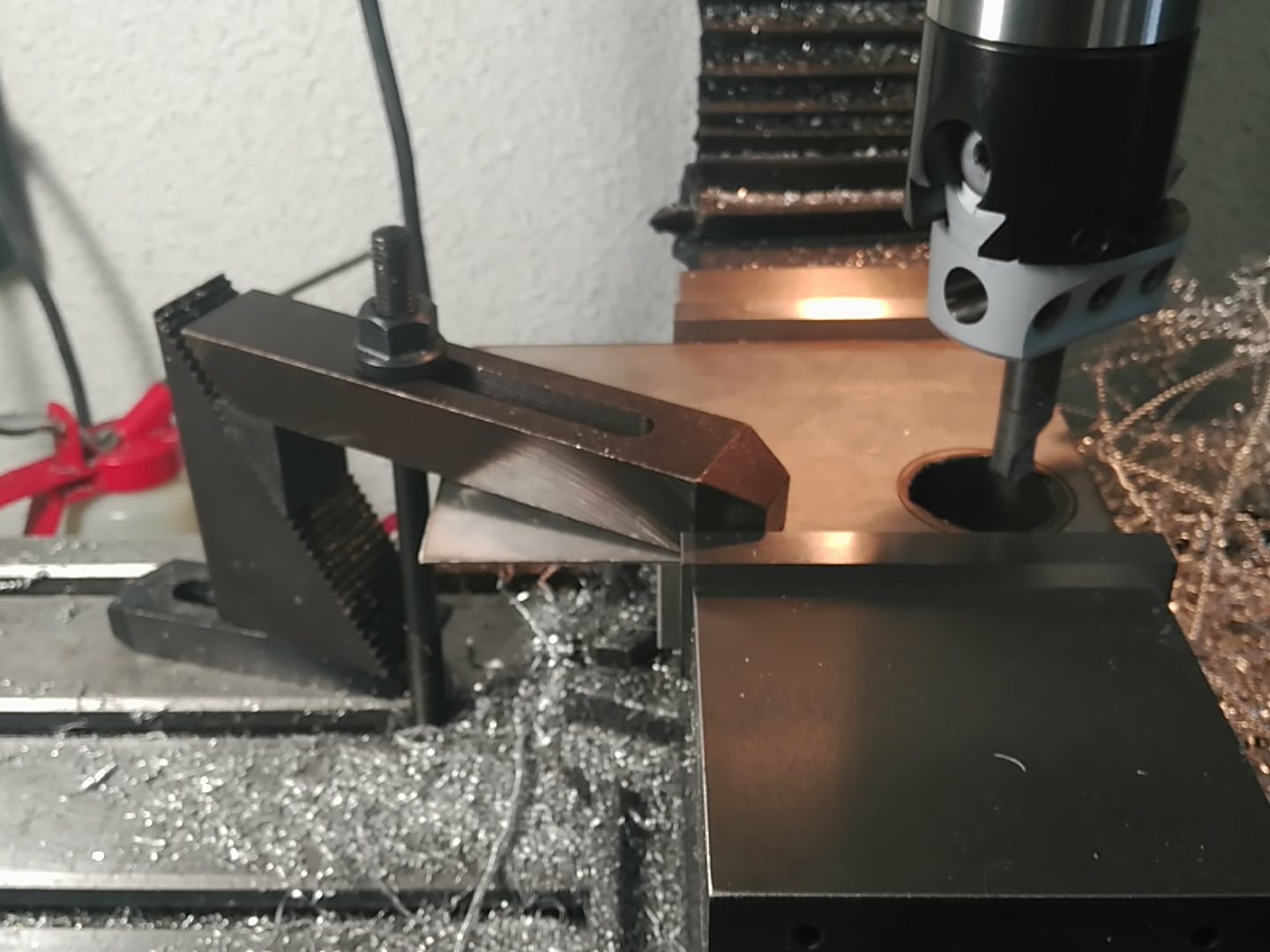
First, pump recess machining:
![]()
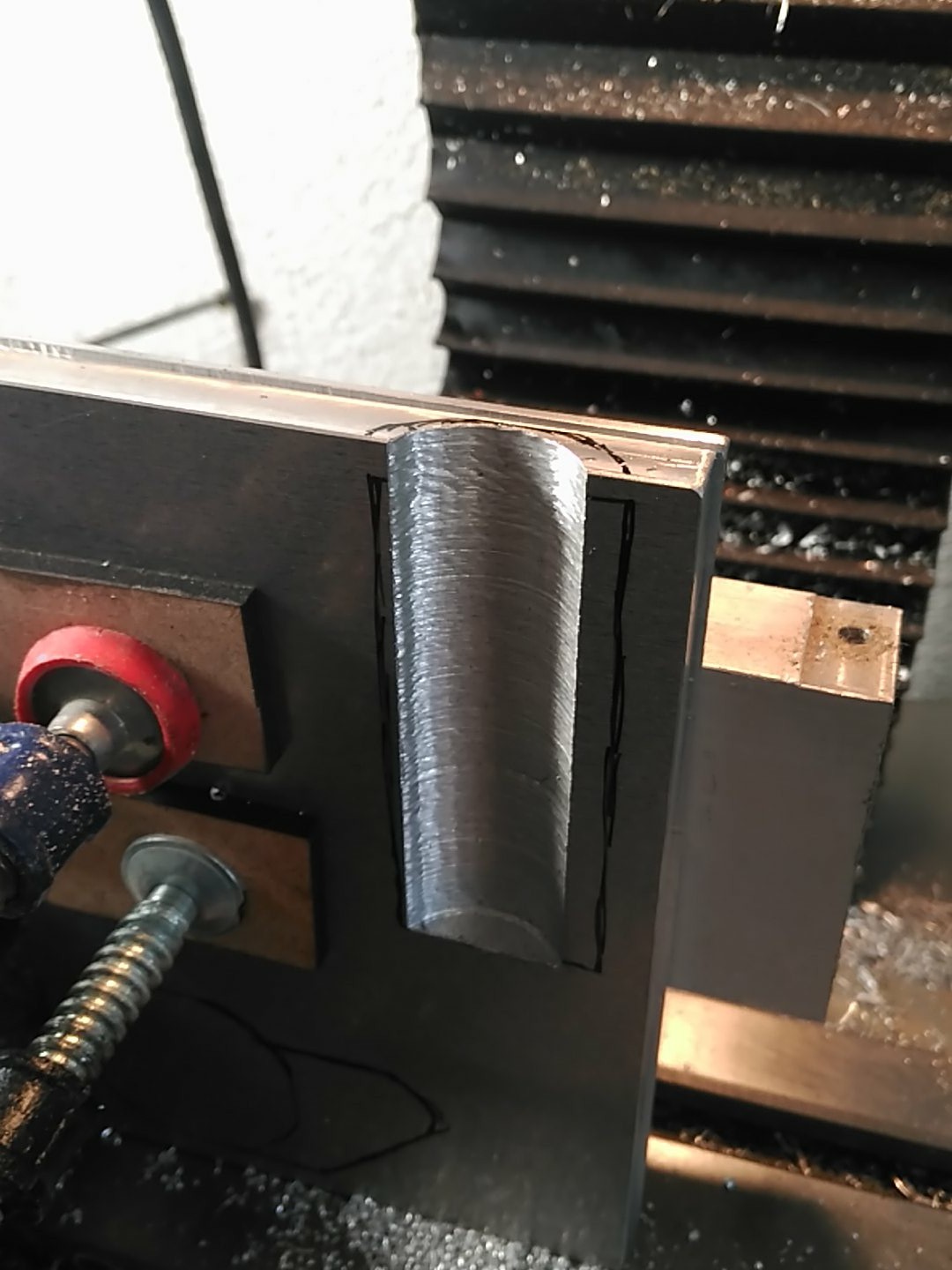
Halfway there:
![]()
The acuum adapter connector was changed to a slimmer one, and thus, the shape of it's recess was also changed on the fly:
![]()
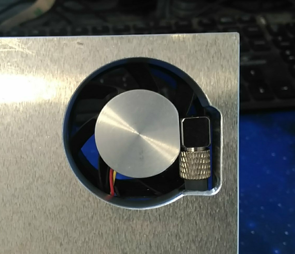
Top side:
![]()
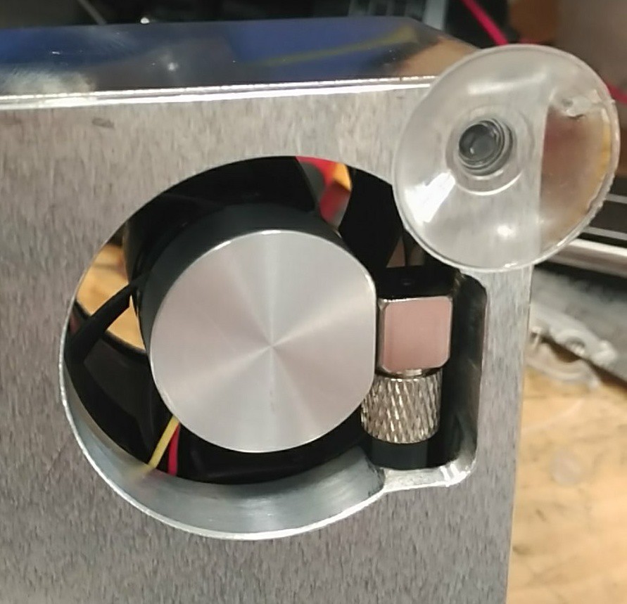
Pump clearance with the power supply:
![]()
I also added suction cups.
![]()
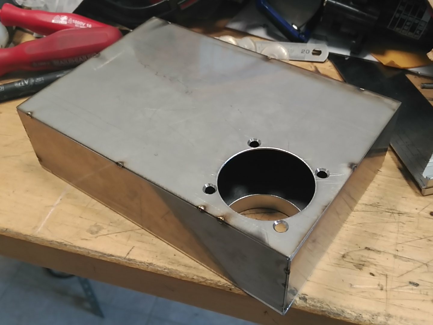
With that done, a stainless case began to take shape:
![]()
Spot welded:
![]()
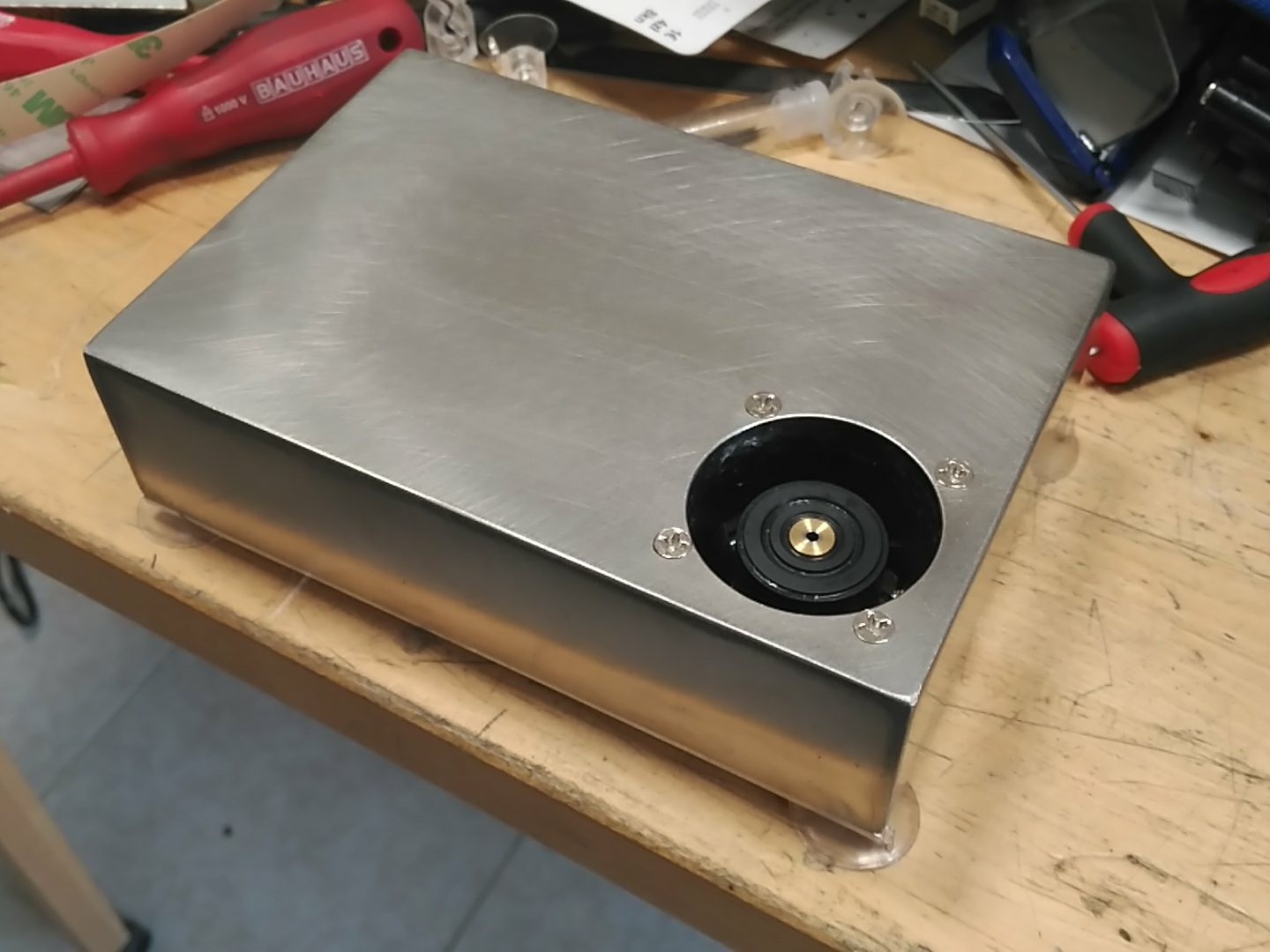
Fully welded and blended:
![]()
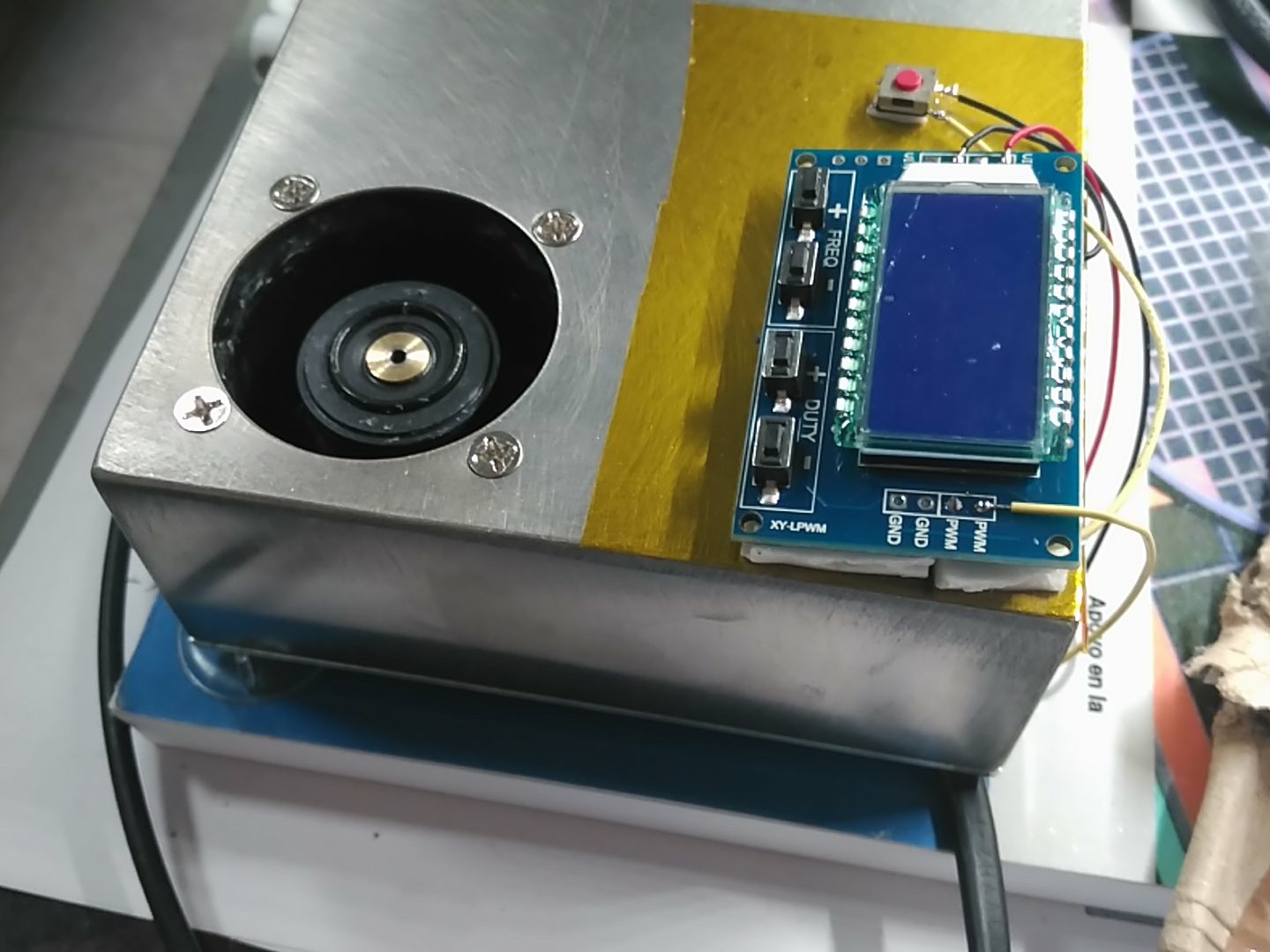
At this point, since I didn't had neither AC connectors nor panel mount buttons, I decided to leave the case like that, and just attach the controller to the outside with double sided tape (over kapton for easy removal) and wait the components.
![]()
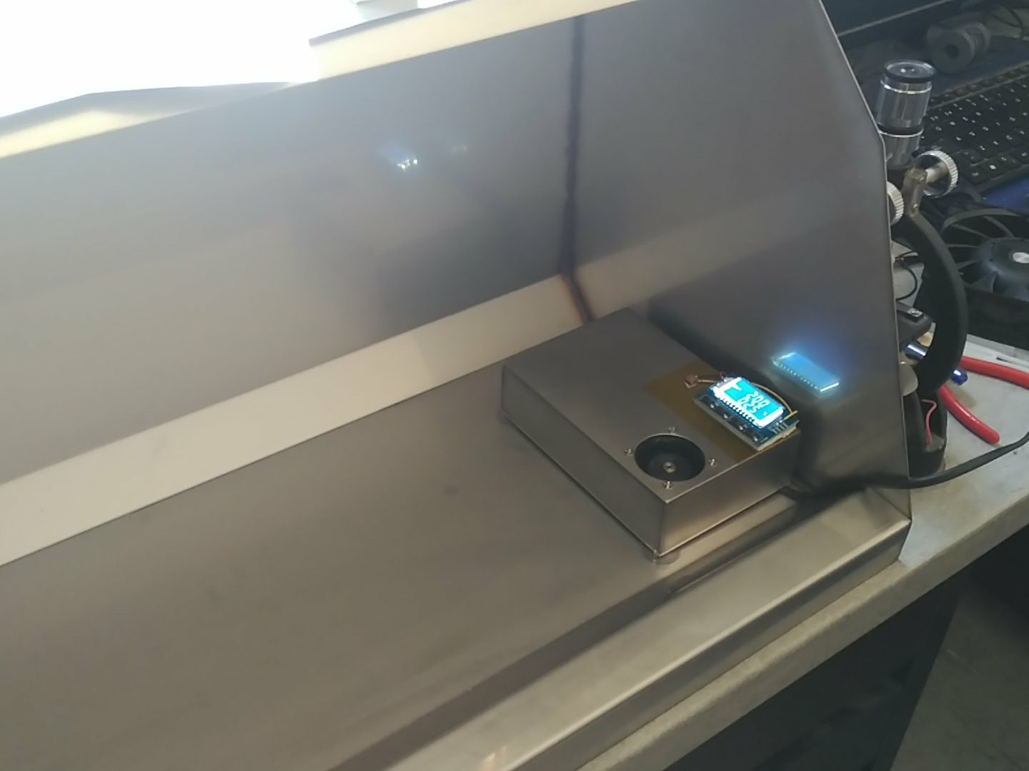
working placement:
![]() There!
There!
I hope the rest of the pieces arrive soon. ^^ -
You spin me right round, baby.
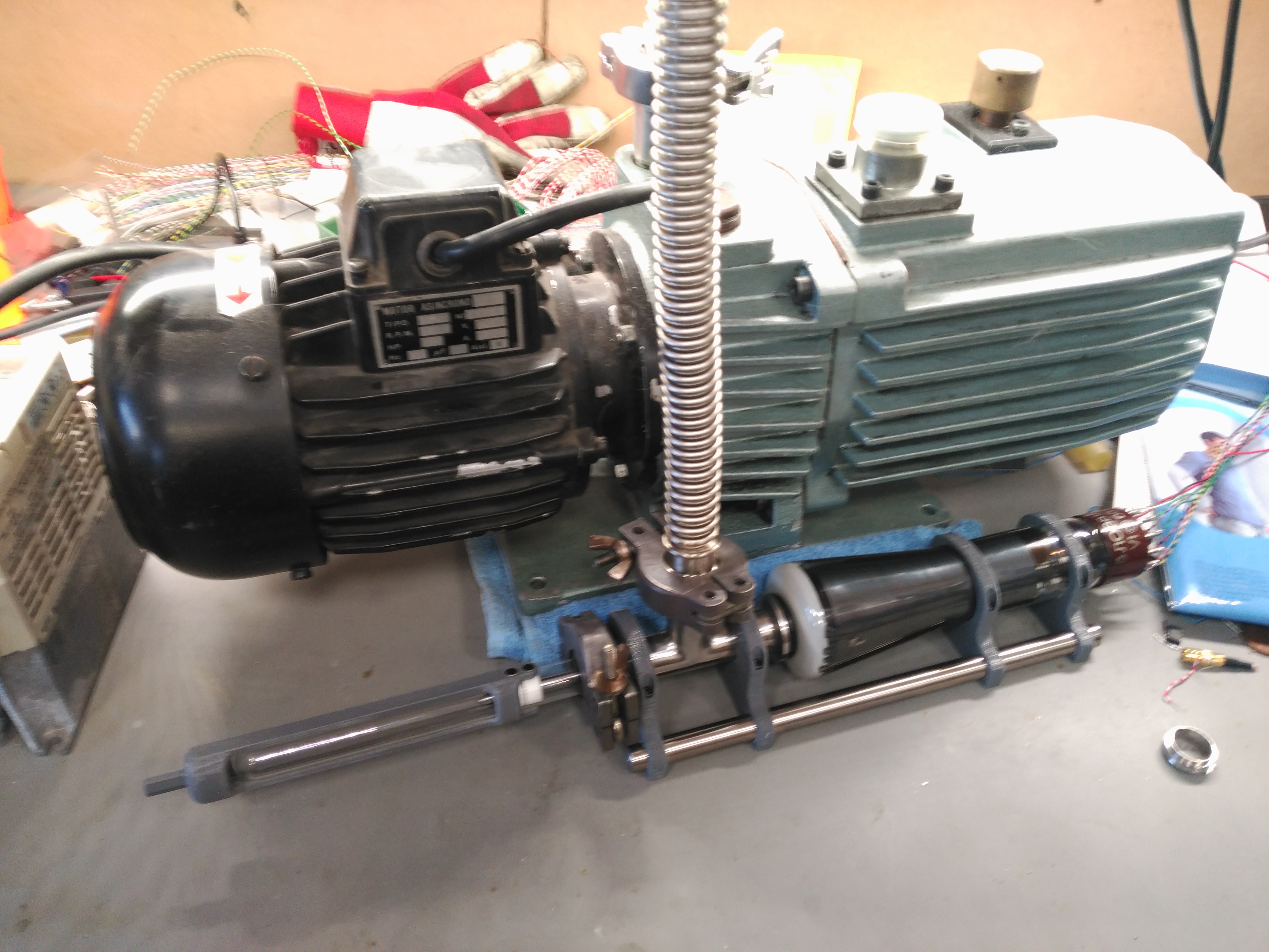
08/01/2018 at 17:36 • 1 commentI finally got into building the spin coater for the project, however, even I was surprised about the way things went.
All I knew is that I wanted a small spin coater, something that could do chip sized things and maybe something a little bigger, but nothing more.
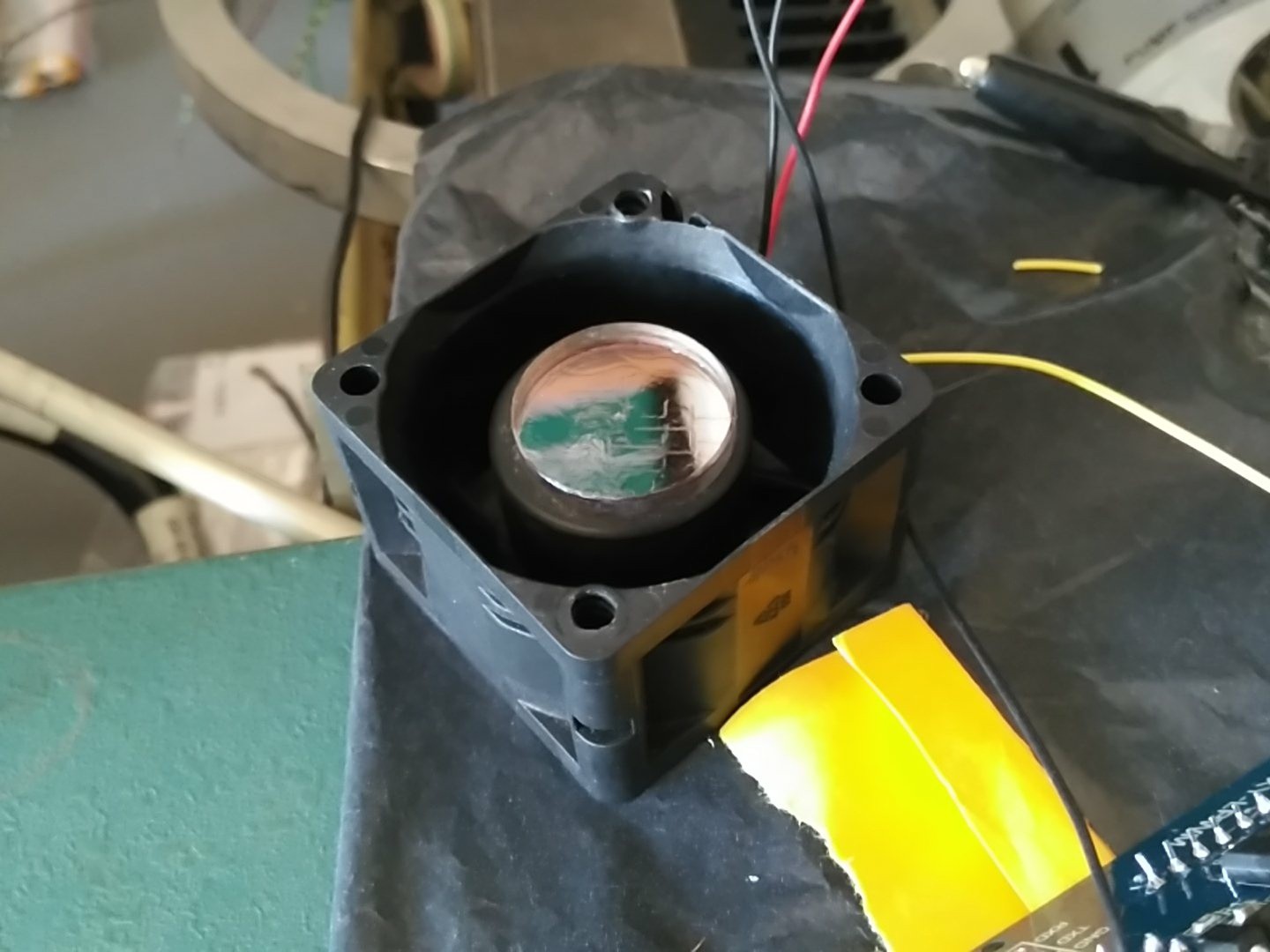
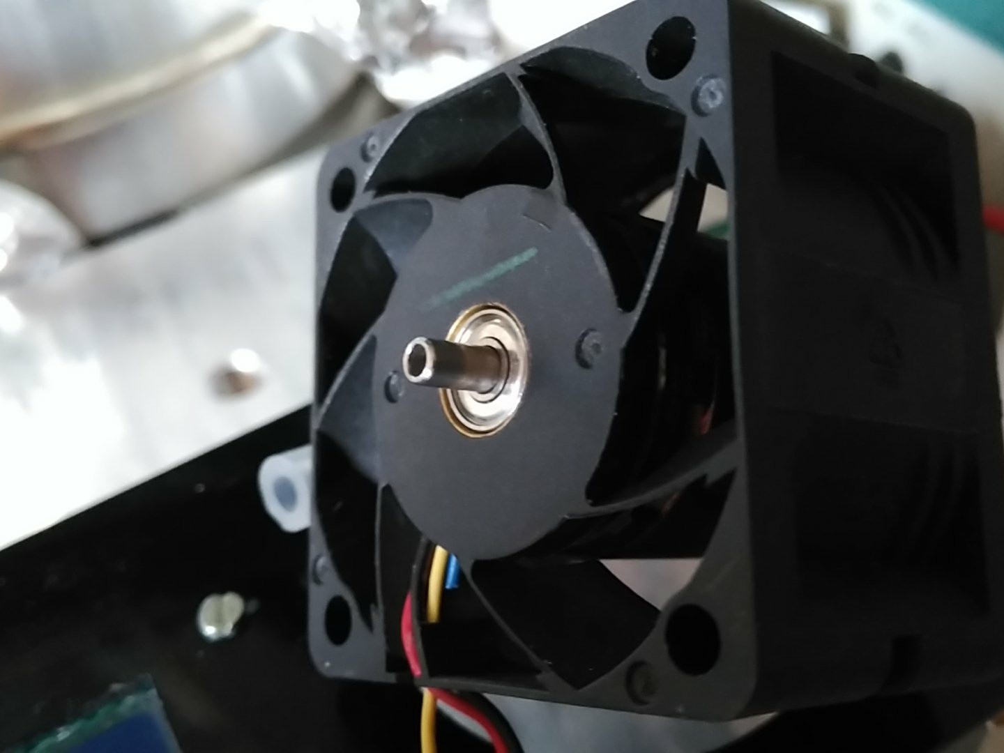
I started with a powerful 40*40mm brushless fan from Delta I had around. It has ball bearings for smooth operation and also it's directly PWM controllable and has smooth start built in. (more about that later)
![]()
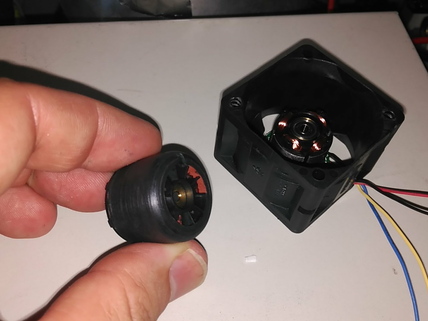
The fins where removed to reduce current consumption:
![]()
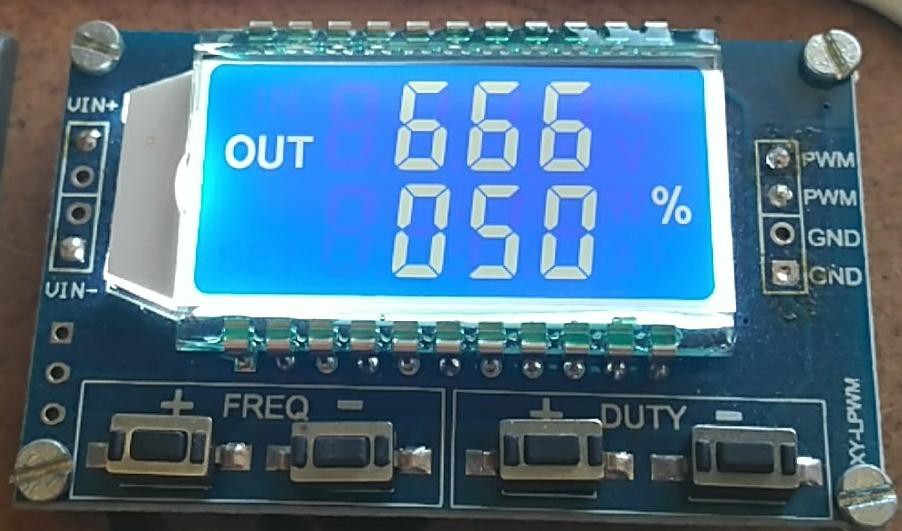
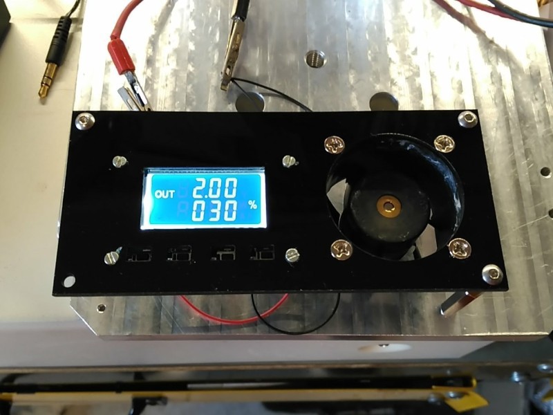
With that, I picked up a simple lcd pwm controller from ebay and hooked it up:
![]()
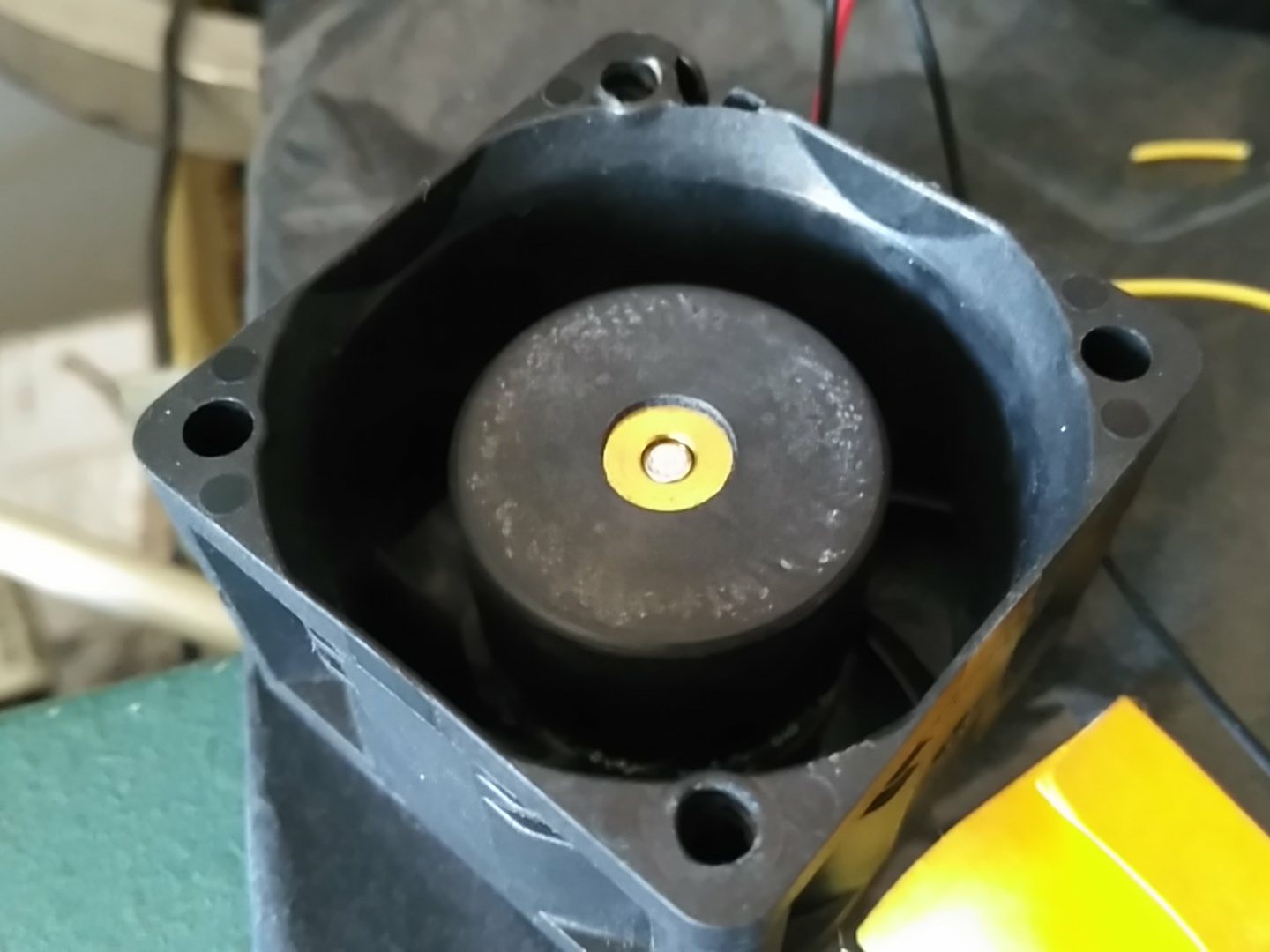
It worked well enough, so I faced the rotor in the lathe.
![]()
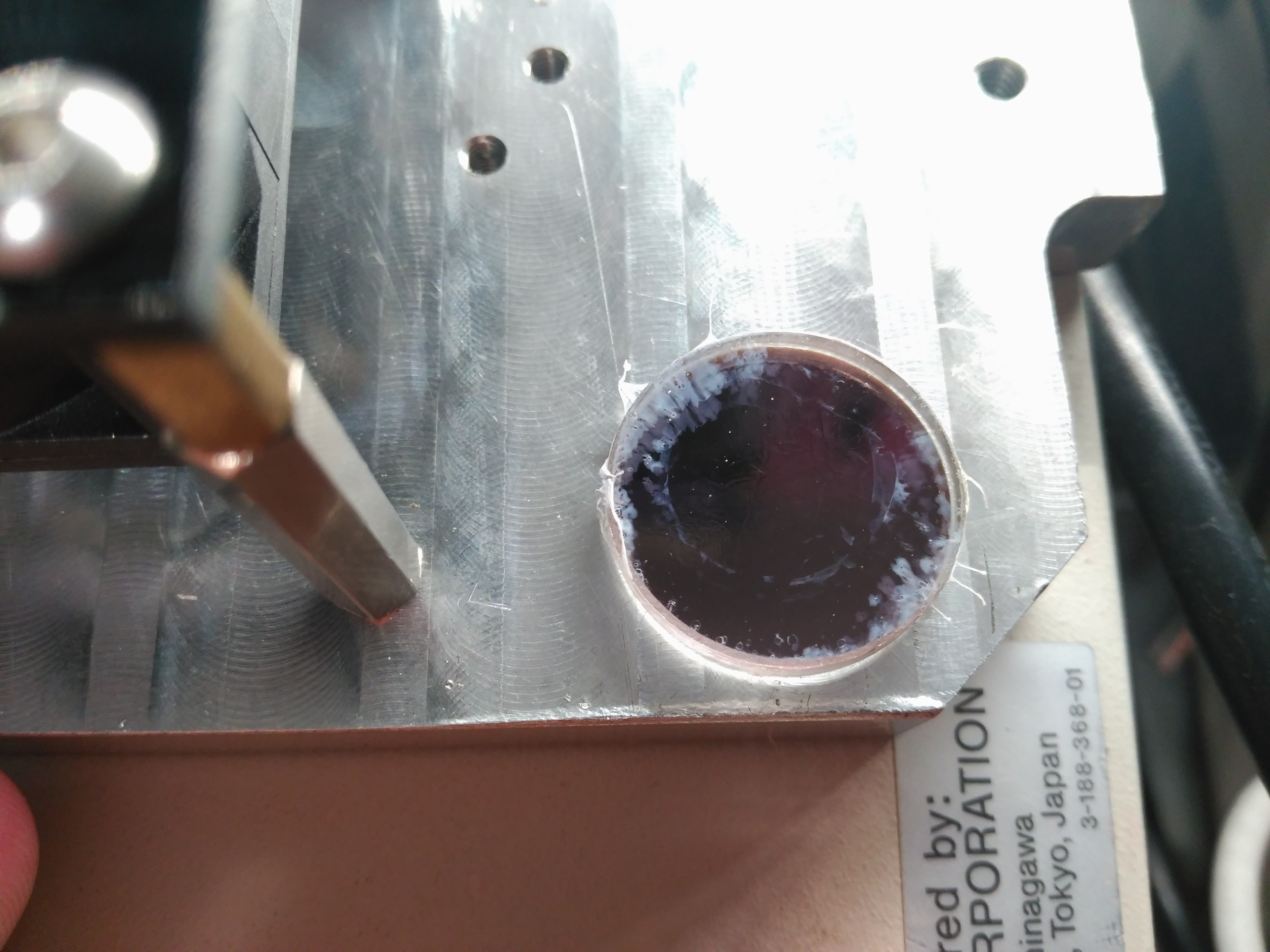
Using double sided tape, I tested a mix of PMMA and acetone:
![]()
It worked well enough, so I quickly cut an acrylic panel and bolted everything together:
![]()
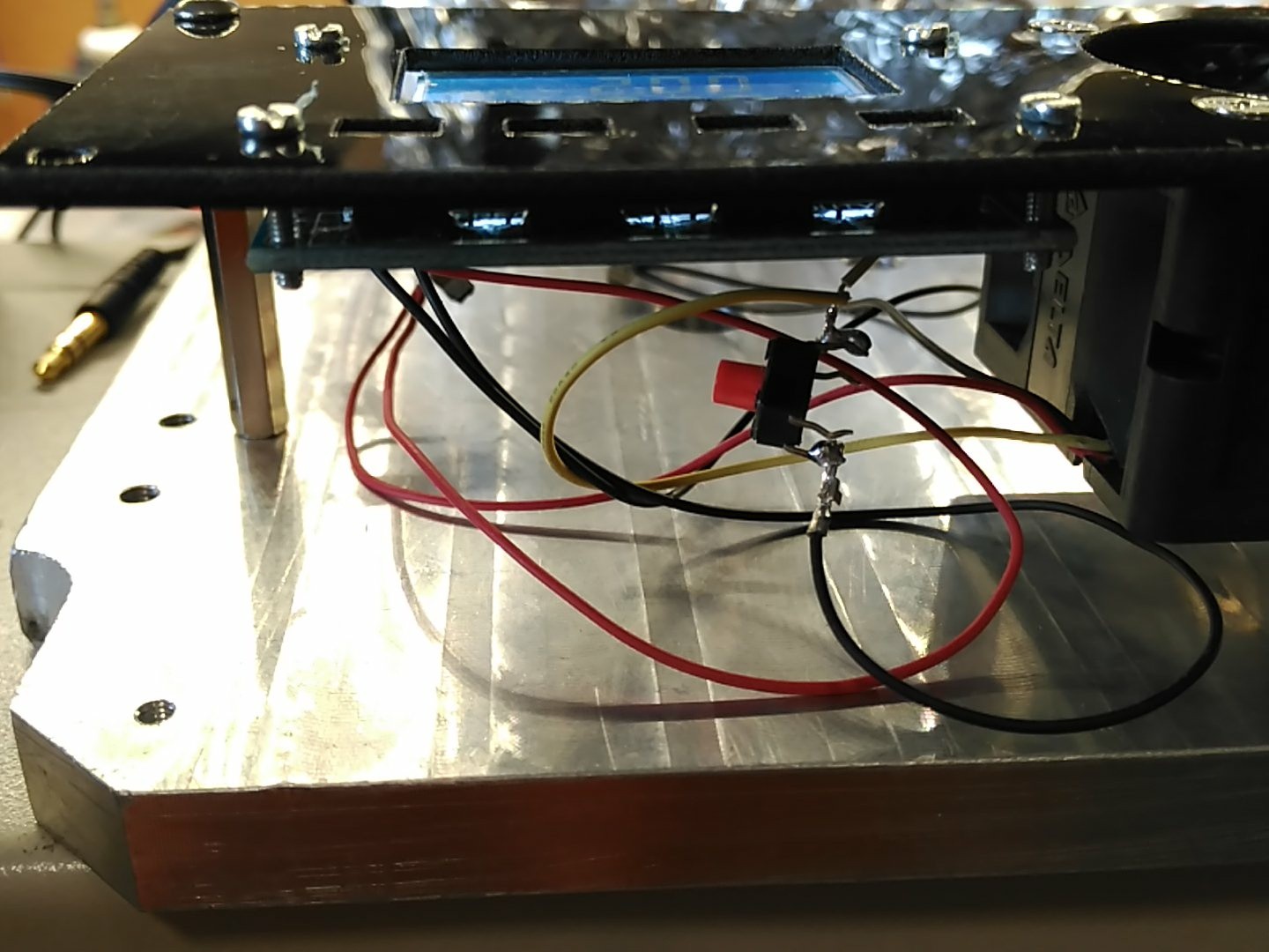
This is a bad moment to discover that you have absolutely ZERO panel pushbuttons and you have to leave the start button dangling underneath:
![]()
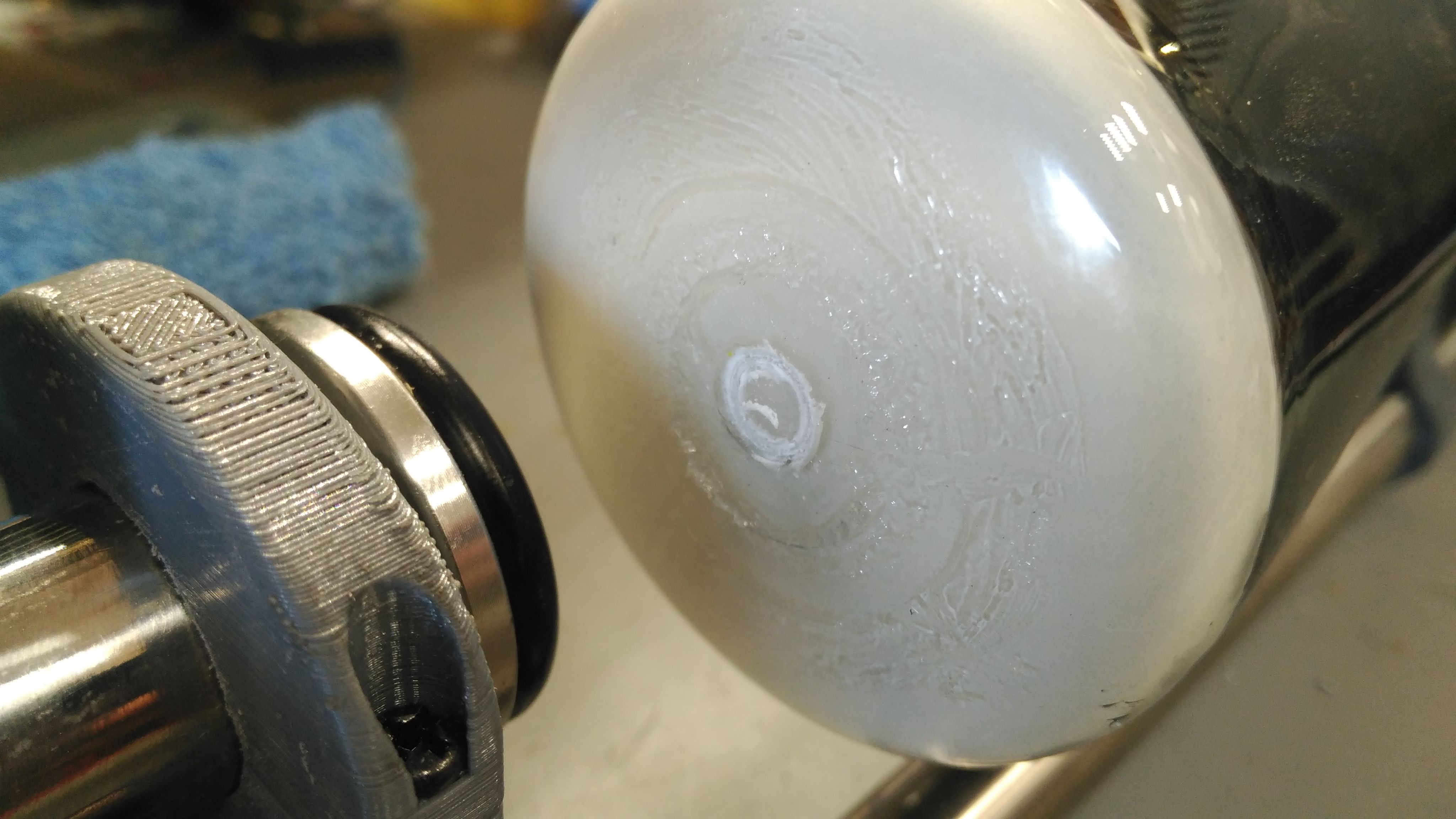
Quick test with double sided tape:
After 25 minutes in the oven @ 150ºC it looked nice. Since I'm using acetone as solvent, it evaporates too quickly, leaving the white marks. With proper technique an better solvents, it should work fine.![]()
Given the results, I was going to leave it at that, but the project had other ideas.
Make it better because your workshop says so.
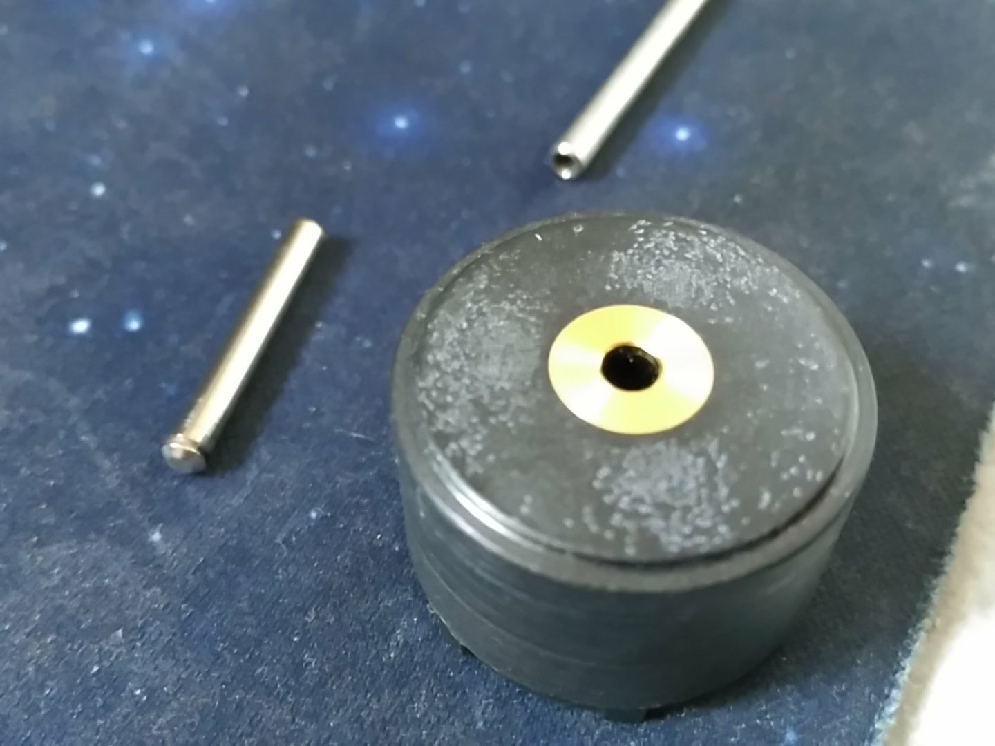
I happened to have some capillary tubes I ordered for the manipulator, but two of them where iron, not stainless. It also happened that one of them had the right diameter (3mm) totally interchangeable with the motor axle!
![]()
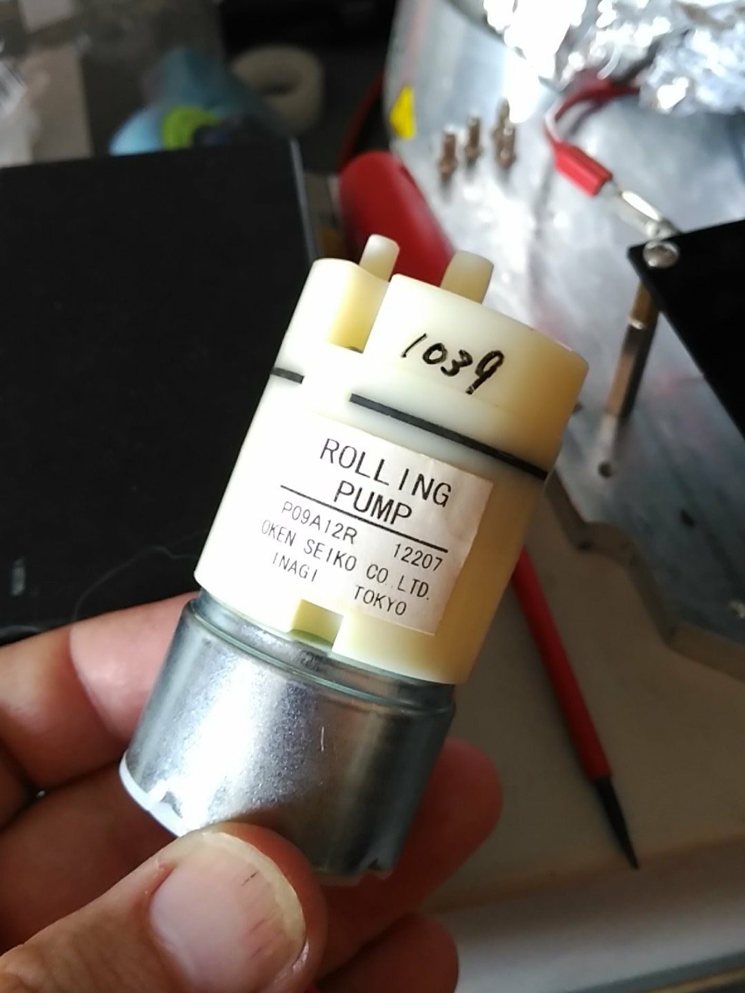
I just needed a vacuum pump, but it was going to be either very expensive, or take waaay too long to get here from china.
I also happen to NOT know very well what my "junk" drawers hold. This time, the pneumatics section did had a 24V vacuum pump ideal for the project!
![]()
So, I pretty much was good to go and try the vacuum chuck thingy.
The axle was changed by simply hammering it in, no need to remachine anything.
![]()
...and extended.
I left it longer than the original to try to protect the ball bearing from any coating that could seep in.![]()
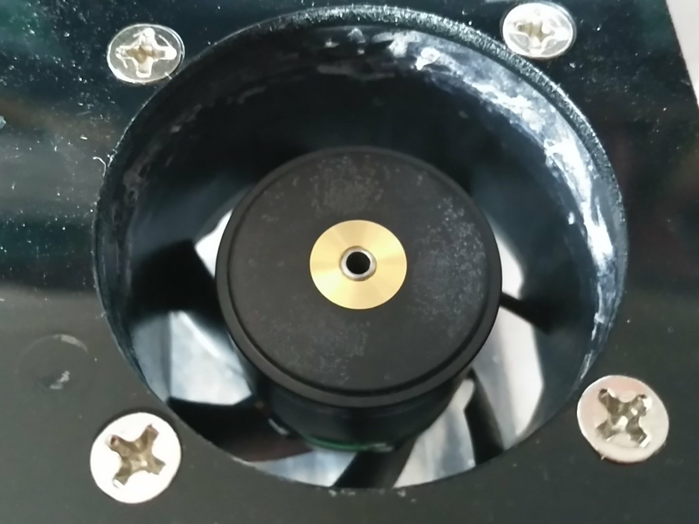
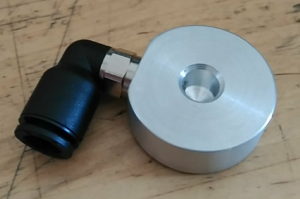
A vacuum tube adapter was machined from scrap aluminium:
![]()
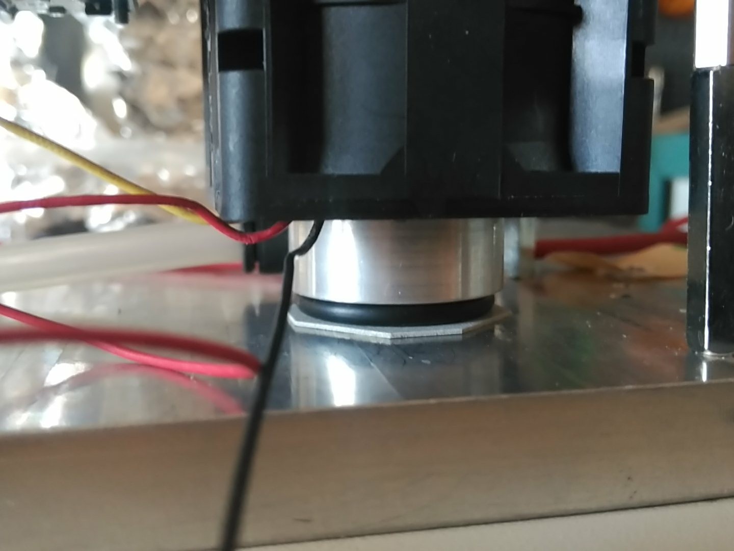
I used double sided tape to hold it in place and test, using an o-ring and some cardboard as spacers so it could not vibrate loose:
![]()
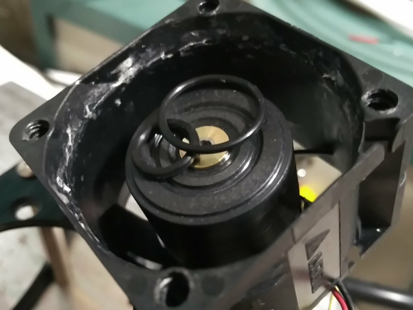
And some grooves where machined to hold two standard 10 and 16mm OD o-rings:
![]()
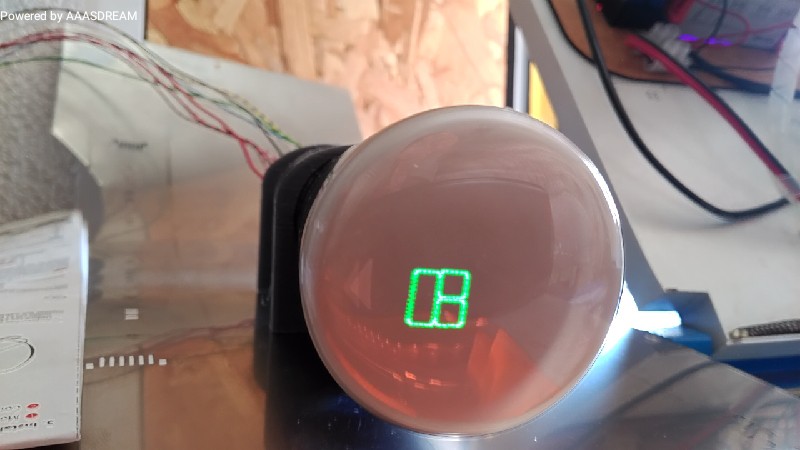
But...does it work?
Hell yeah it does!
(5550 rpm)
It also works well with odd shaped glass:But does the vacuum chuck make any difference, or is it working by sheer chance? Let's choke the vacuum line and see:
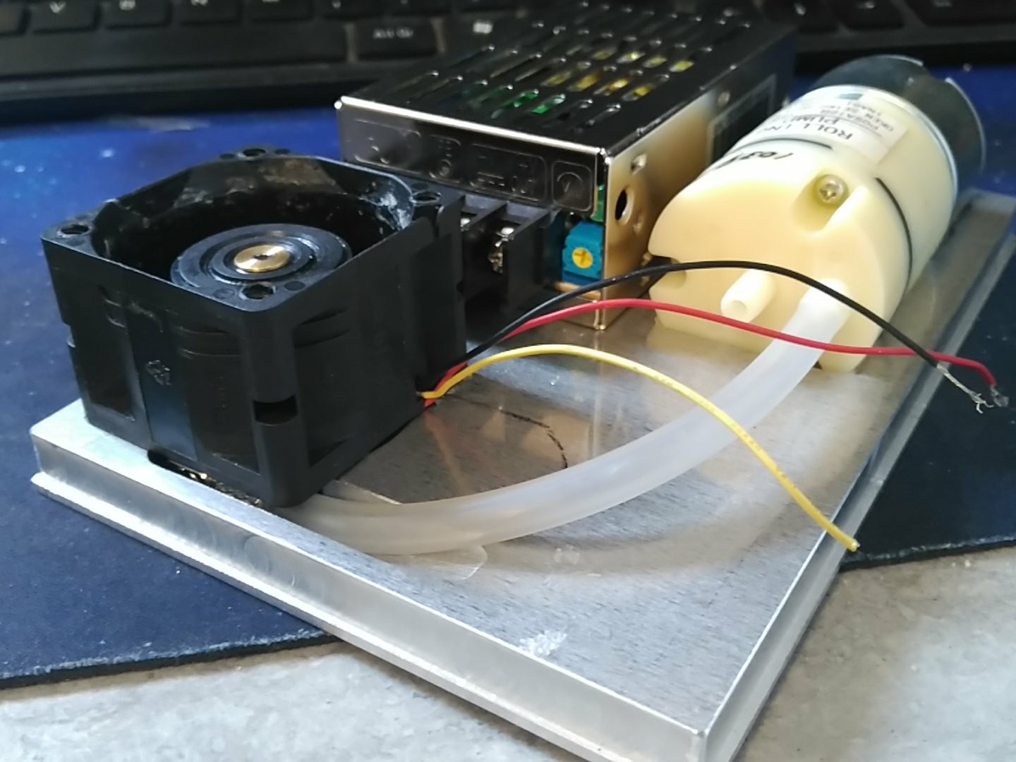
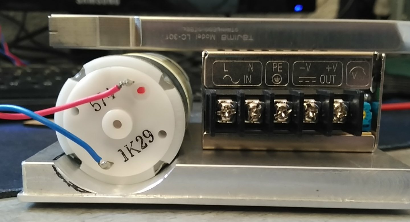
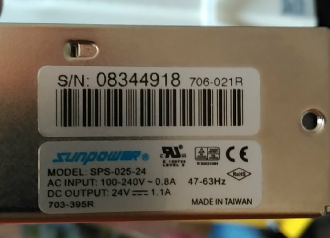
As for power, I had lying around a 24V 1A switching power supply:![]()
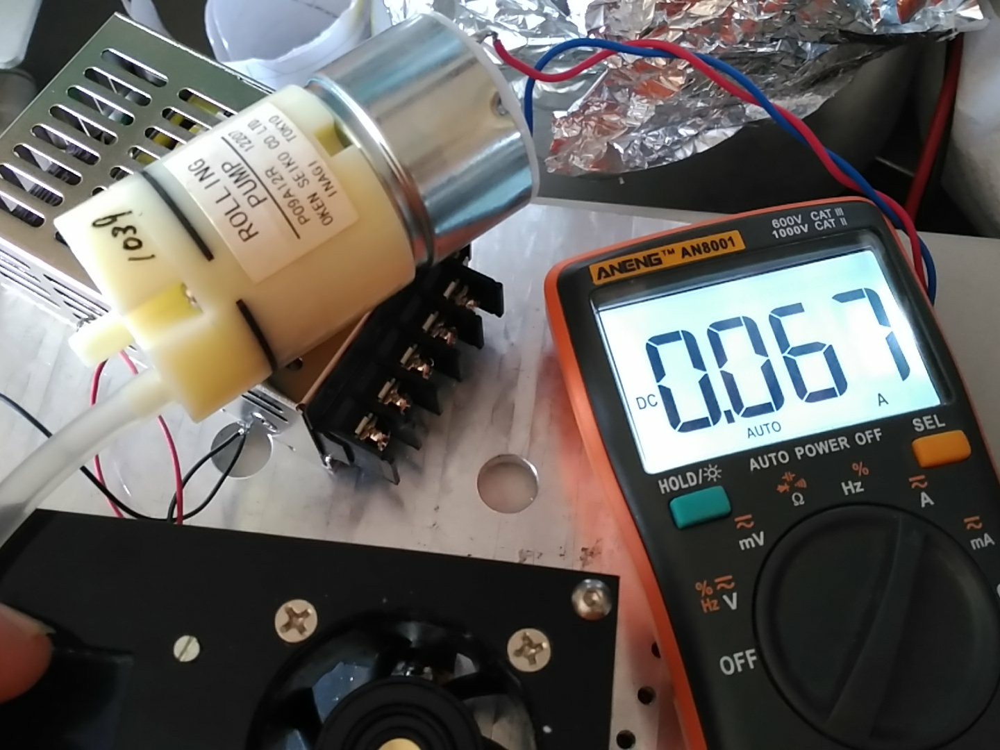
Initially I was also looking for a 12V power supply for the spin motor, but a quick measurement of the consumptions later:
(choked vacuum pump)
![]()
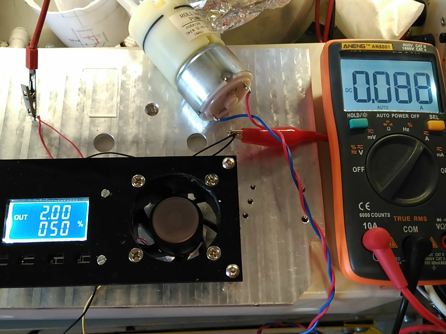
(spin motor with chuck ON)
![]()
With those kinds of powers, I can just simply throw a 7812, heatsinked for the lulz, and call it a day. Also remember that the smooth start prevents the spin motor from drawing lots of current, killing two birds with one stone.
As final note, let's talk about speeds.
This motor is not a normal computer fan. This is a high power, 18500 rpm nominal, 800mA brushless motor. Usually, the final RPM's @ 100% power depend on the density of the air and many other variables, so using it without modifications would require direct measurement and/or characterization.
HOWEVER...
Since all the fins have been removed, all the power goes to only mantain the speed, as there is almost no drag (compared to the fan sucking air) so we can be pretty sure that 50% speed will be very near half rpm's and any other divisions we can come up with.
On the funy side, the chuck can't hold anything that is not super centered past 50% rpms. That sounds bad, right?
Well, 50% is 9250rpm, much, much faster tan any spin-on coat I have heard of. The highest I have ever heard is 7000rpm for super fine coatings (nm) and this coater will do tat at 38%. So, unless I need something really, REALLY weird, I think I'm good.
Of course, a comercial machine has controlled spin-up curves and timings and so on, but frankly, this one can be built for next to nothing (maybe 25€ in important parts), the motor itself has smooth start built in (so it doesn't just smear the liquid with brutal acceleration) and it has a friggi'n VACUUM CHUCK, you can't ask for a better cost/performance ratio, seriously.
Metal case building for the spincoater!
https://hackaday.io/project/107598-semiconductors-home/log/150537-case-closed-spincoater-ii
-
Under the Hood. (part 2)
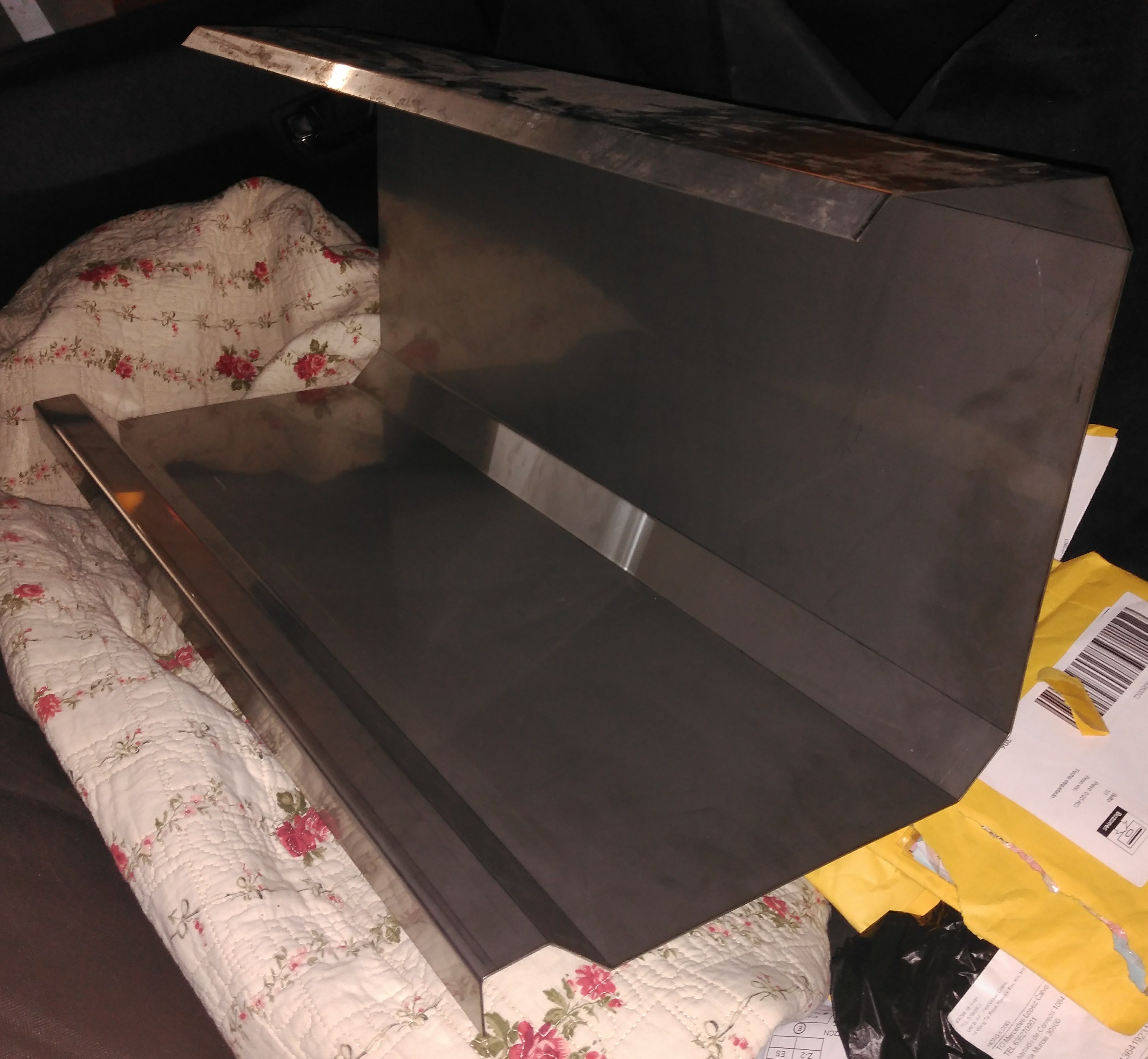
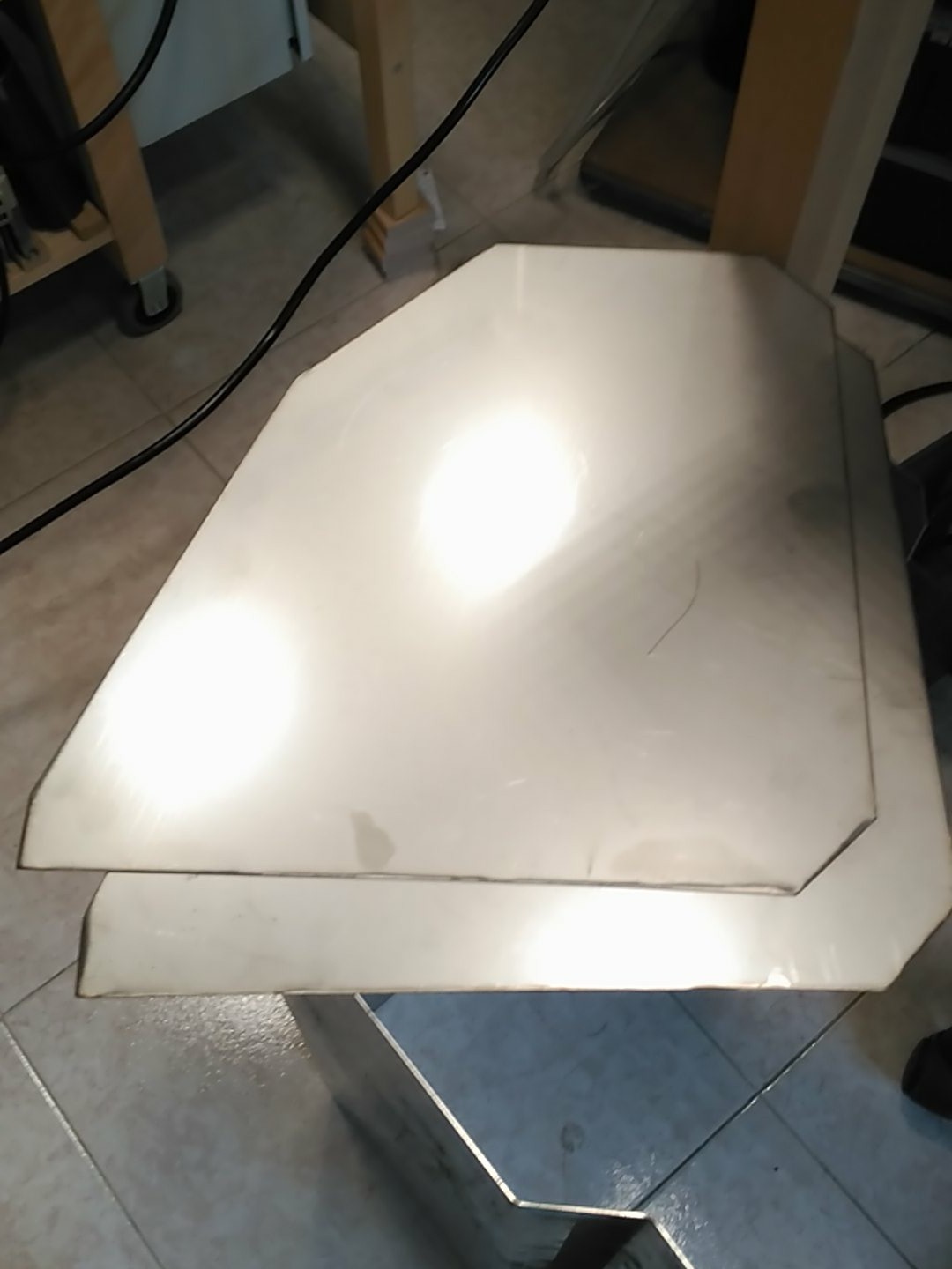
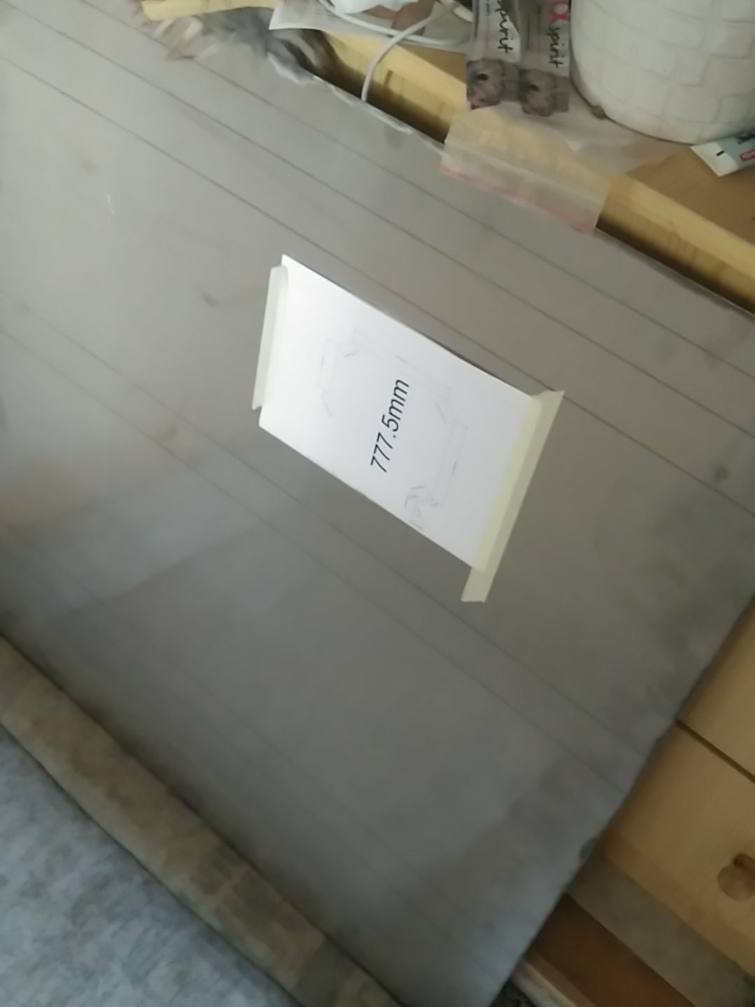
07/27/2018 at 19:46 • 0 commentsSo, after much waiting, the metal sheet got bent. At least, the service was cheap enough to compensate the wait.
![]()
Once I got home, I could not resist to put it on the table and see how it looked.
![]()
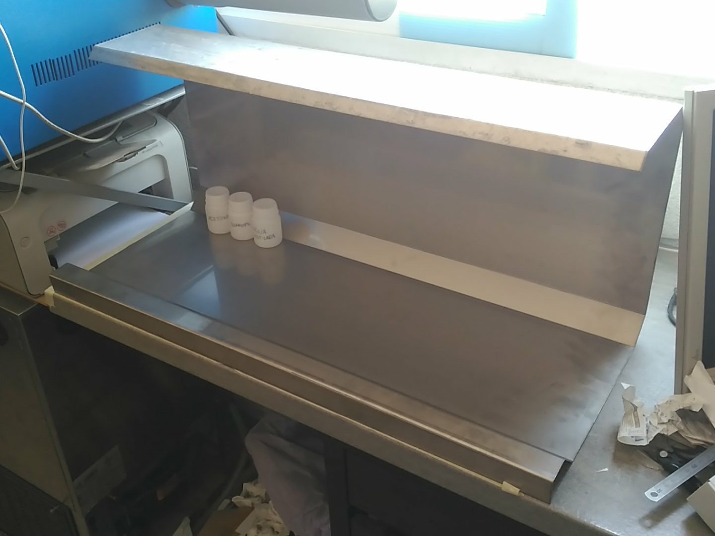
I was very satisfied, so the sideplates where traced:
![]()
And cut:
![]()
Some tack-welding later for fitting:
![]()
It looks damn gorgeous!
The armrest also works as small-spill contention:
![]()
Just missing the sidewelds, extraction circuit and the front acrylic shield, but I almost can't wait to start working with it!! ^^
-
Smalleing: Laser, Interrupted.
07/25/2018 at 12:31 • 0 commentsWhen we left, the PMMA trenches where about 200µm wide and 100µm deep. The idea, to further etch it so the bottom of the trench would reveal the substrate below, allowing for, hopefully, 100µm wide stencil bottom.
Soon it was revaled that some spacing (50µm) had to be added in between starts and stops, otherwise, the laser would overetch in the corners because of stepover.
![]()
With said spacing, the result was much better:
![]()
That continued into some paterning* tests:
*(no relation to actual semicon paterning)Squareish:
![]()
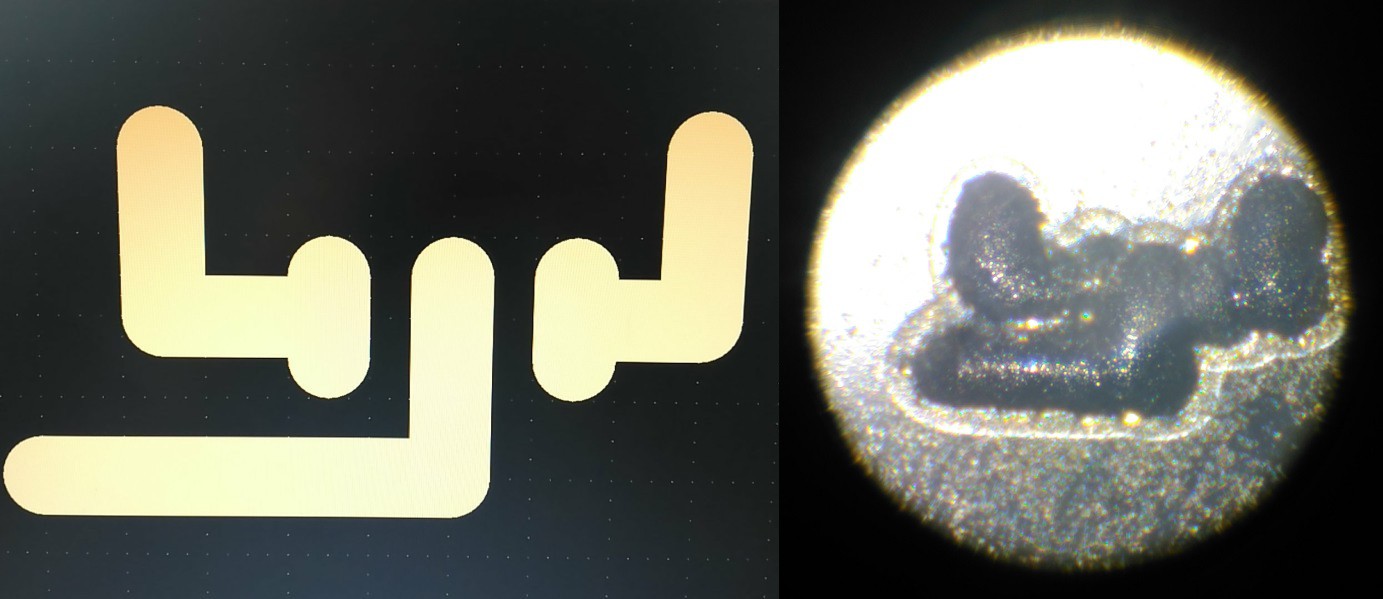
Imaginary fet:
![]()
After that, I thought that was it, however, my brain had other plans.
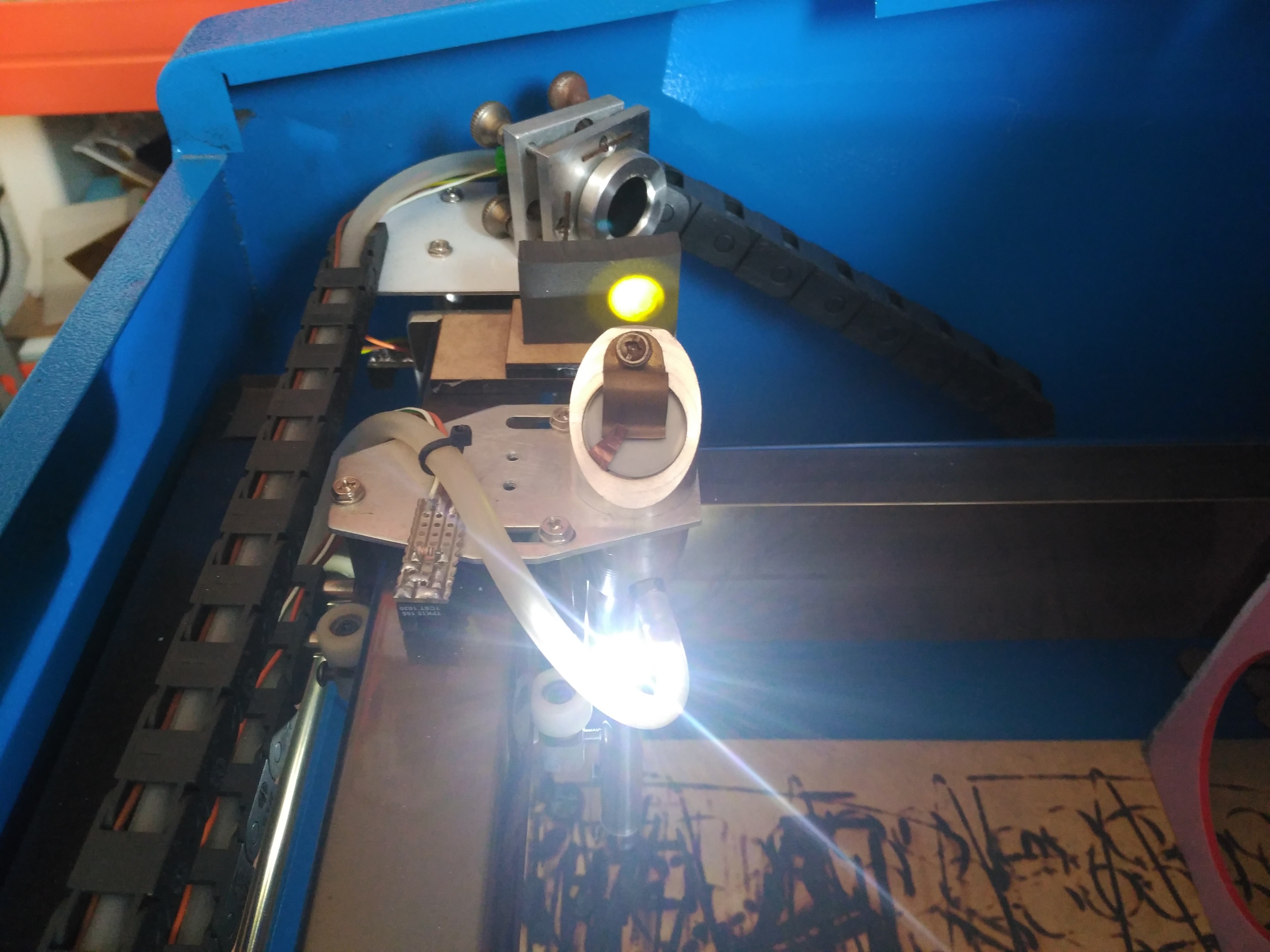
It thought about getting rid of the useless parts of the laser beam, and concentrating on the etching, using a graphite "Hot Trap" as iris. That way, I could increase the power in the laser tube to have more consistency (lowest amperages behave a bit erratically), but not burn through the PMMA layer.
![]() On top: Beam backward tracing with a flashlight so I can position the graphite block.
On top: Beam backward tracing with a flashlight so I can position the graphite block.
Result:
Smaller and much more defined trenches!
About 2/3 the width of previous tests and 50% shallower depth of trench (aout 50µm deep).
Good enough as to have rendered the 50µm spacing obsolete.
This should enable higher precision in the mask, requiring a gap of 25µm between endpoints, and closer spacing between trenches.![]()
I'm having so much fun XDDDD
See you in the next installment!!
-
Turbopun!
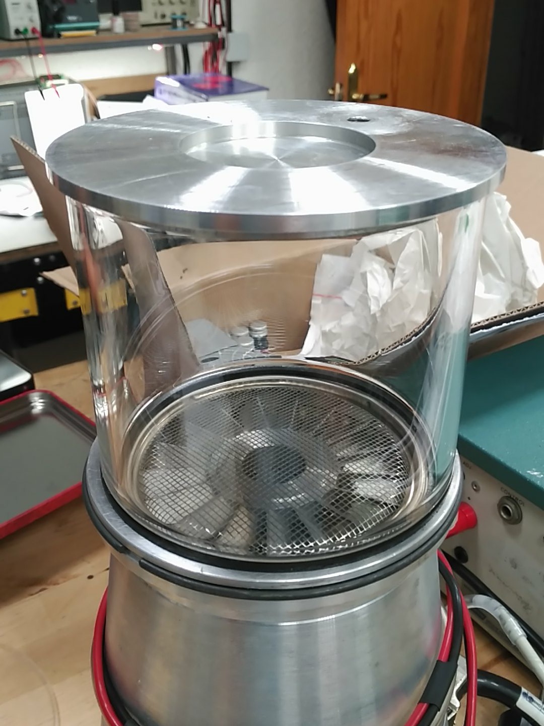
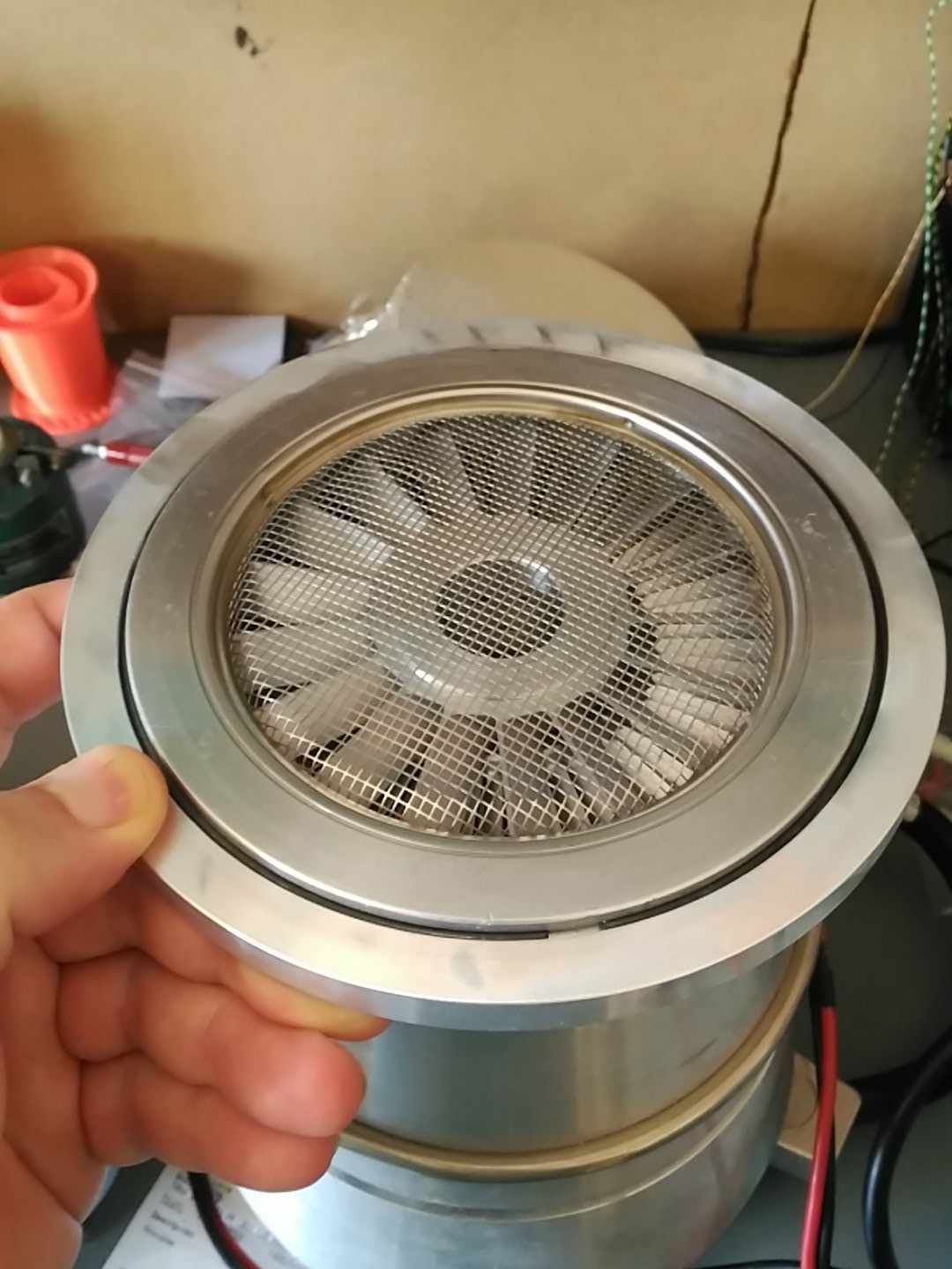
07/25/2018 at 11:51 • 0 commentsThe turbomolecular pump arrived and I got a first look at what I was dealing with. It was much more massive than I thought it would be. ^^U
![]()
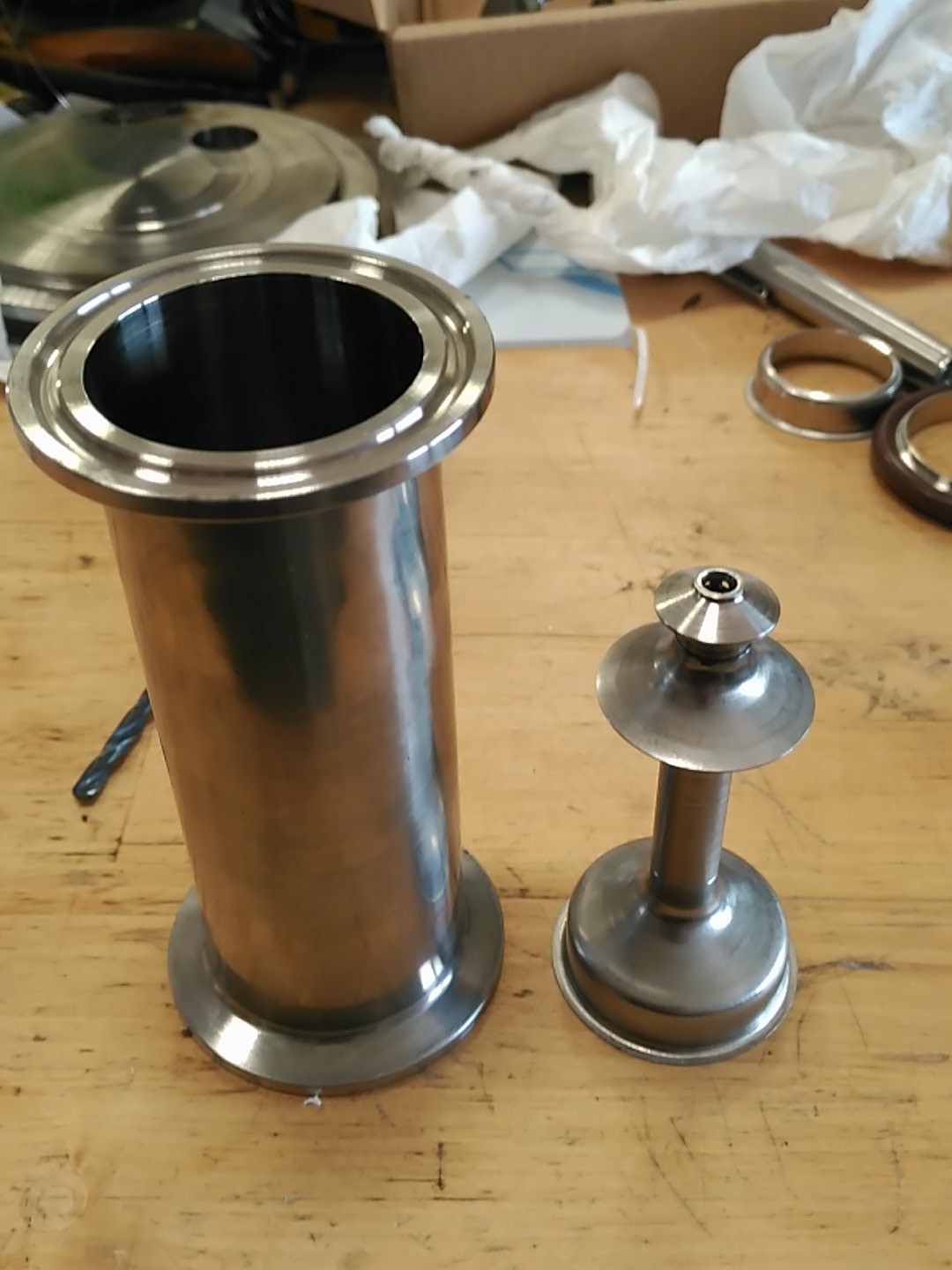
That's my vacuum chamber on top of the turbo. Now it looks absurd to do make some kind of adapter.
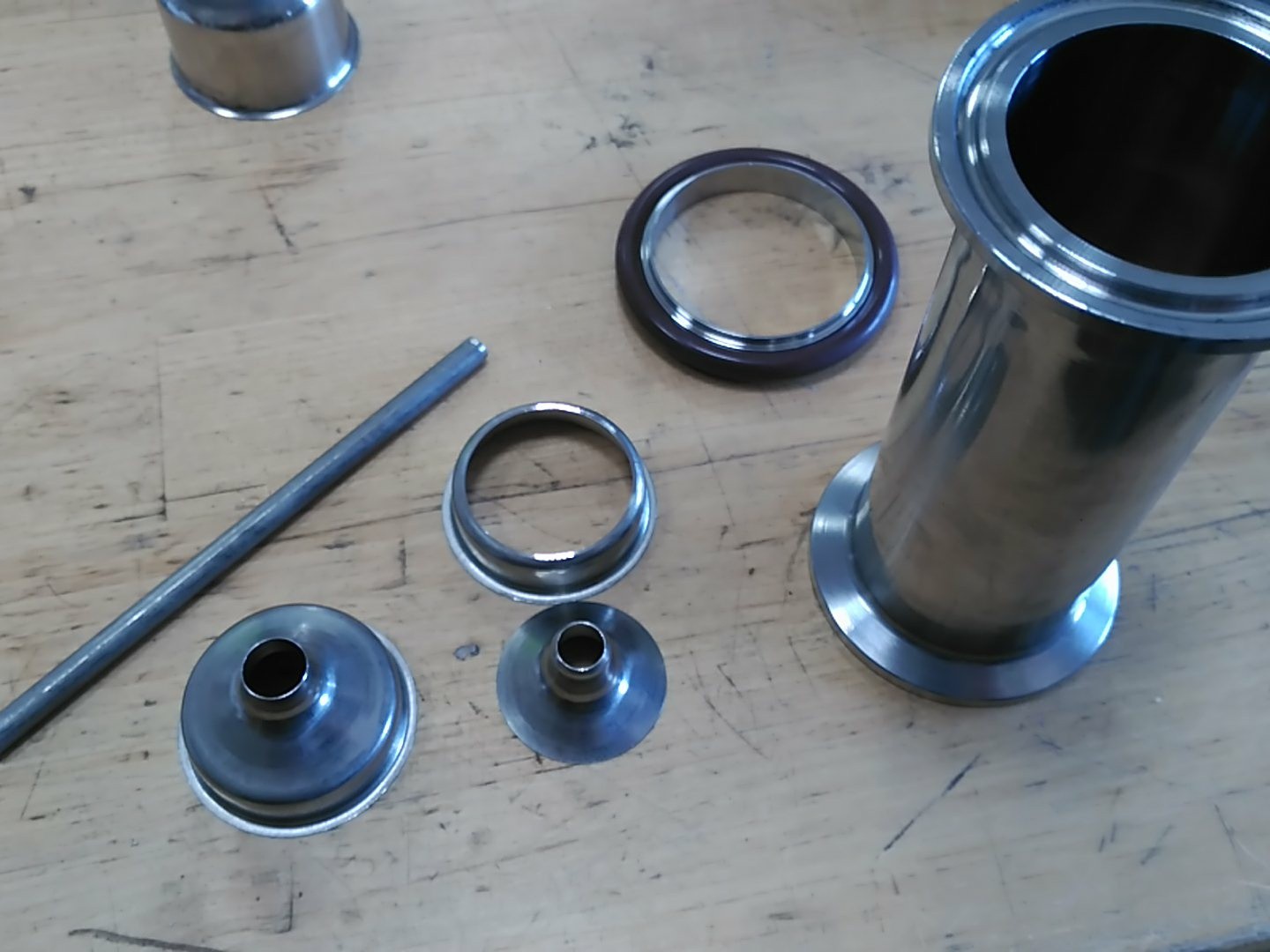
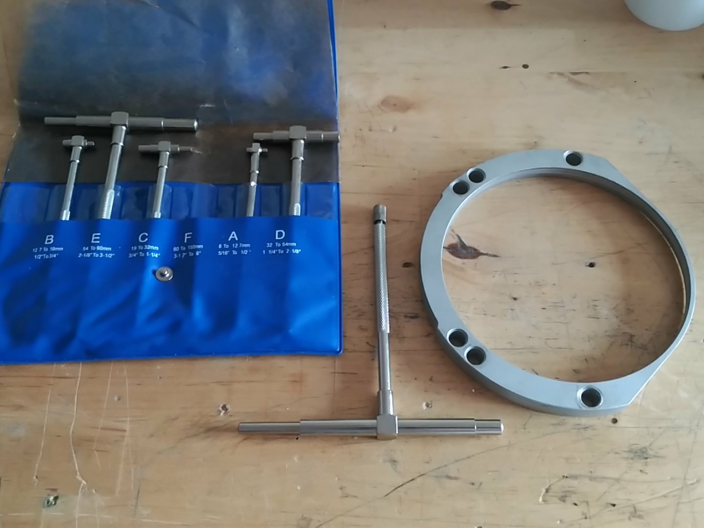
The pump came with a holding ring, but it had a weird shape and clamping holes, so I decided to make a new one:
![]()
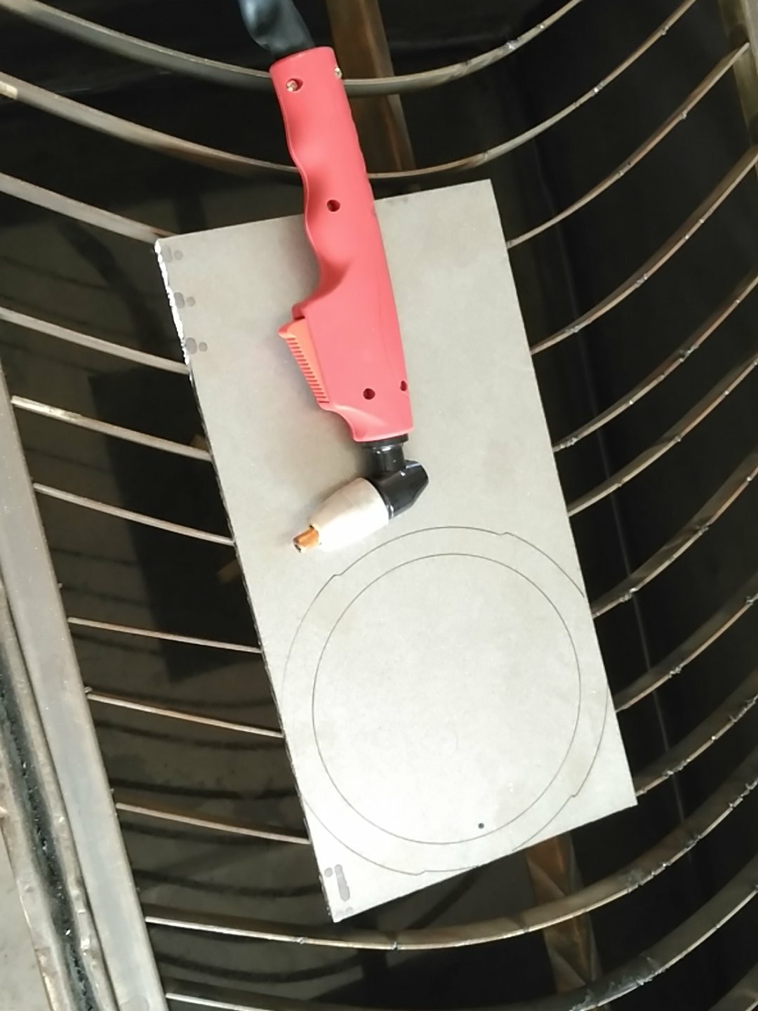
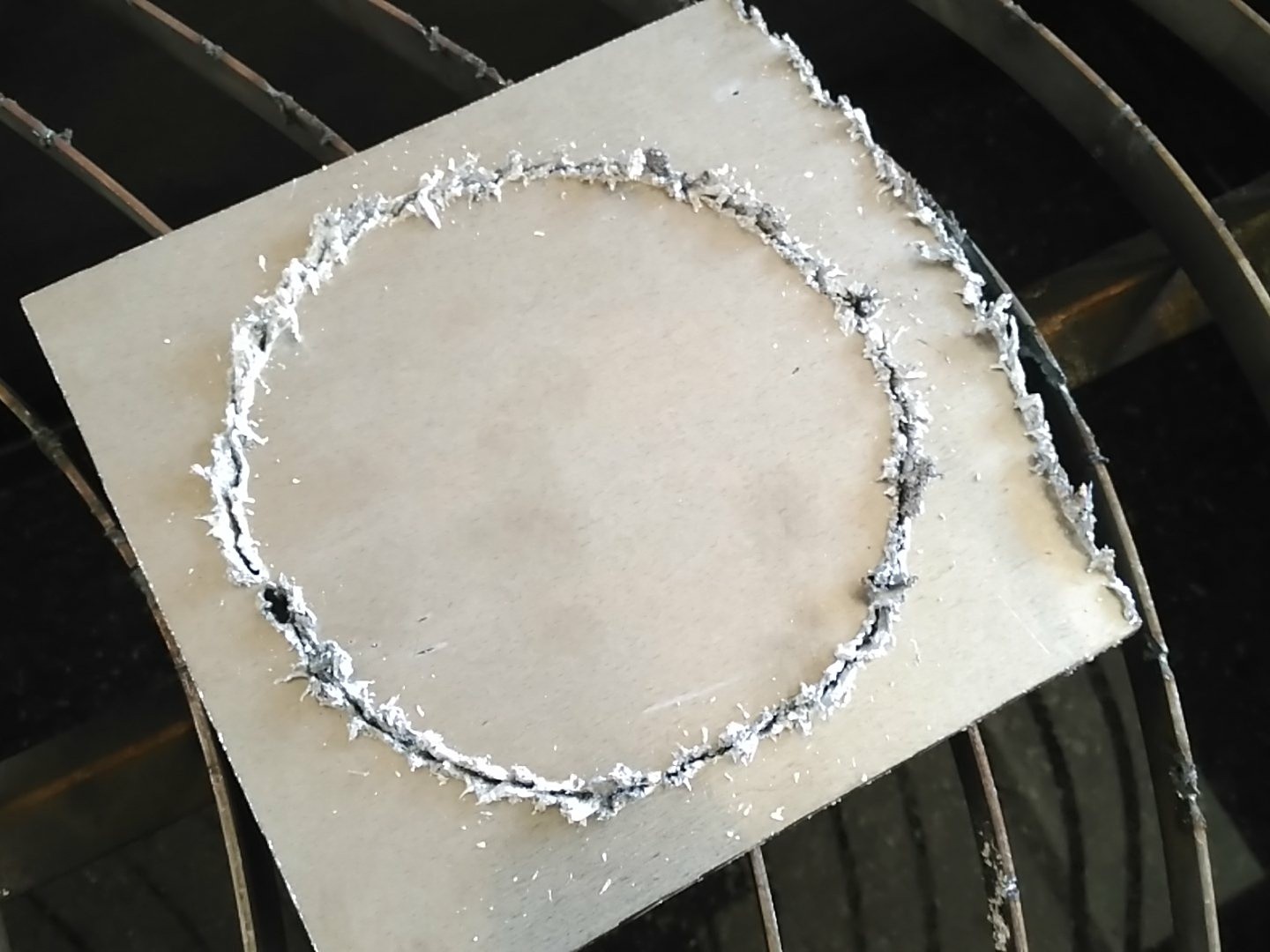
At first I was going to CNC machine it, but I messed it up a bit, so got angered and decided to machine it by hand, cutting the "ring" from the stock with my new cheap plasma cutter:
![]()
This is probably at the limit of what this super cheap machine can do, but hey, it took me only 5 minutes to cut, so it was well worth:
![]()
Nothing that can't be cleaned with the angle grinder. XD
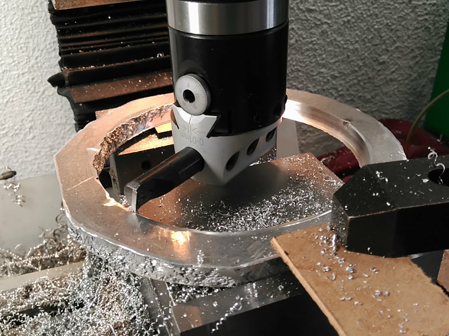
It looks much nicer from the top, tough.After that, it was mounted on the milling machine and brought to dimensions:
![]()
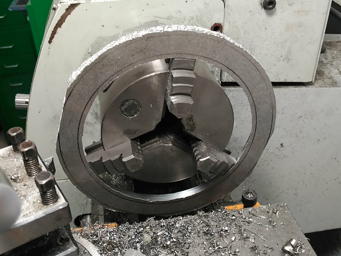
The outside perimeter and faces where finished in the lathe, wich was at it's workholding limit, btw:
![]()
It came out okay, with a bit of extra play, but nothing that can't be lived with.
![]()
Tha will tension the top of the chamber so it can't disastrously open to atmosphere. I won't drill the holding holes until I figure out how to tension everything.
-
The wafer in the PMMA mask
07/15/2018 at 19:58 • 0 commentsSo, while waiting for the turbopump to arrive, my mind was left meandering around, and thinking about the PMMA masking, and the difficulty to obtain very low molecular weight masking liquid...
I thought...
If Silicon is sort of transparent to 10600nm laser light...but PMMA is not...can't I just use laser etching to patern low resolution features on my test wafers?
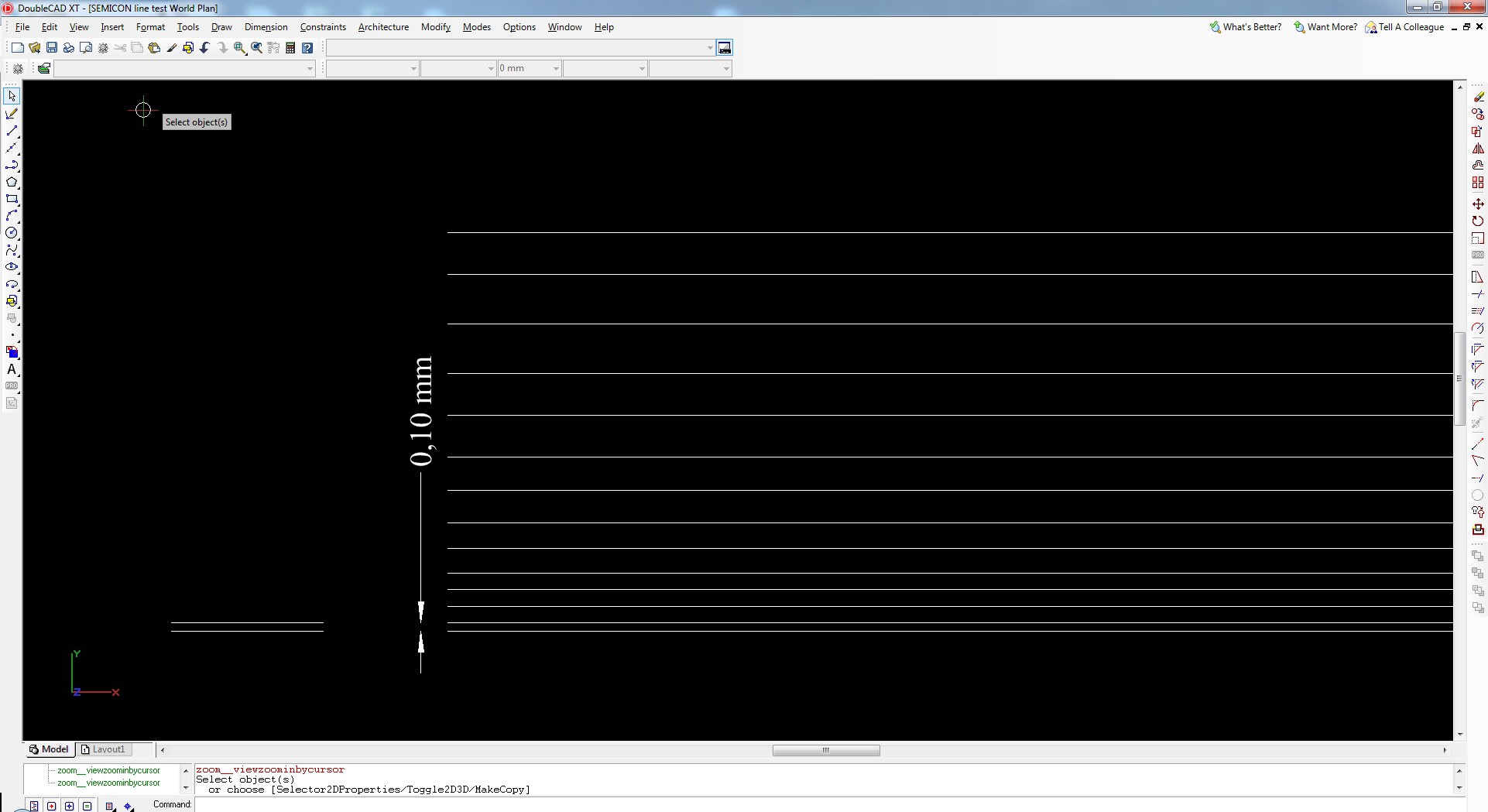
With that thought, I prepared a test vector file with lines separated 100µm - 200µm - 300µm for the laser cutter:
![]()
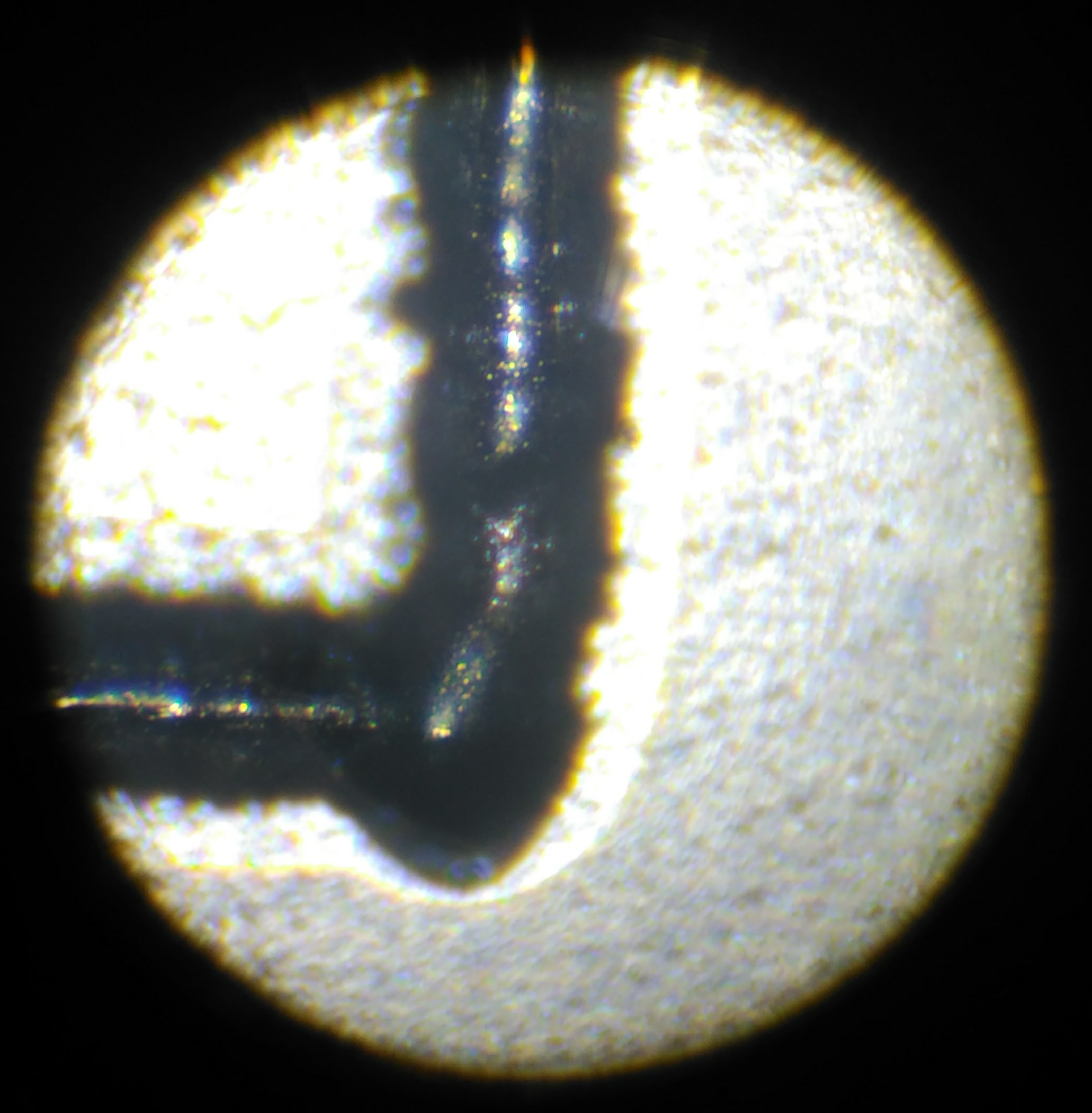
After lasing that, I mcgyvered this microscope to see the tiny details:
![]()
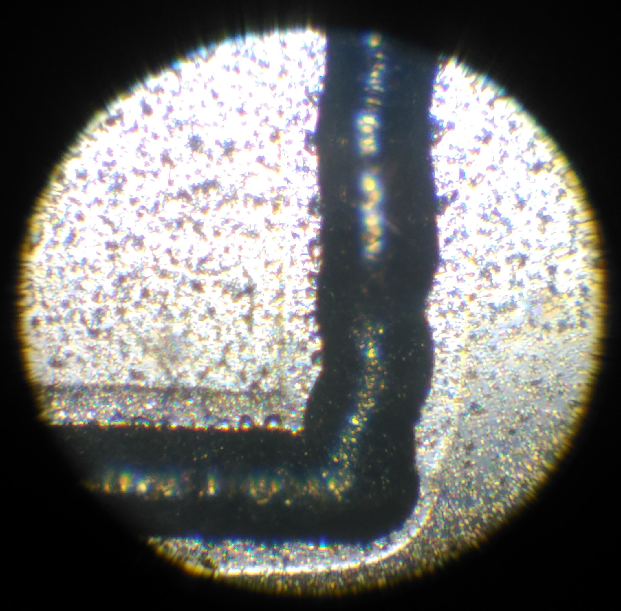
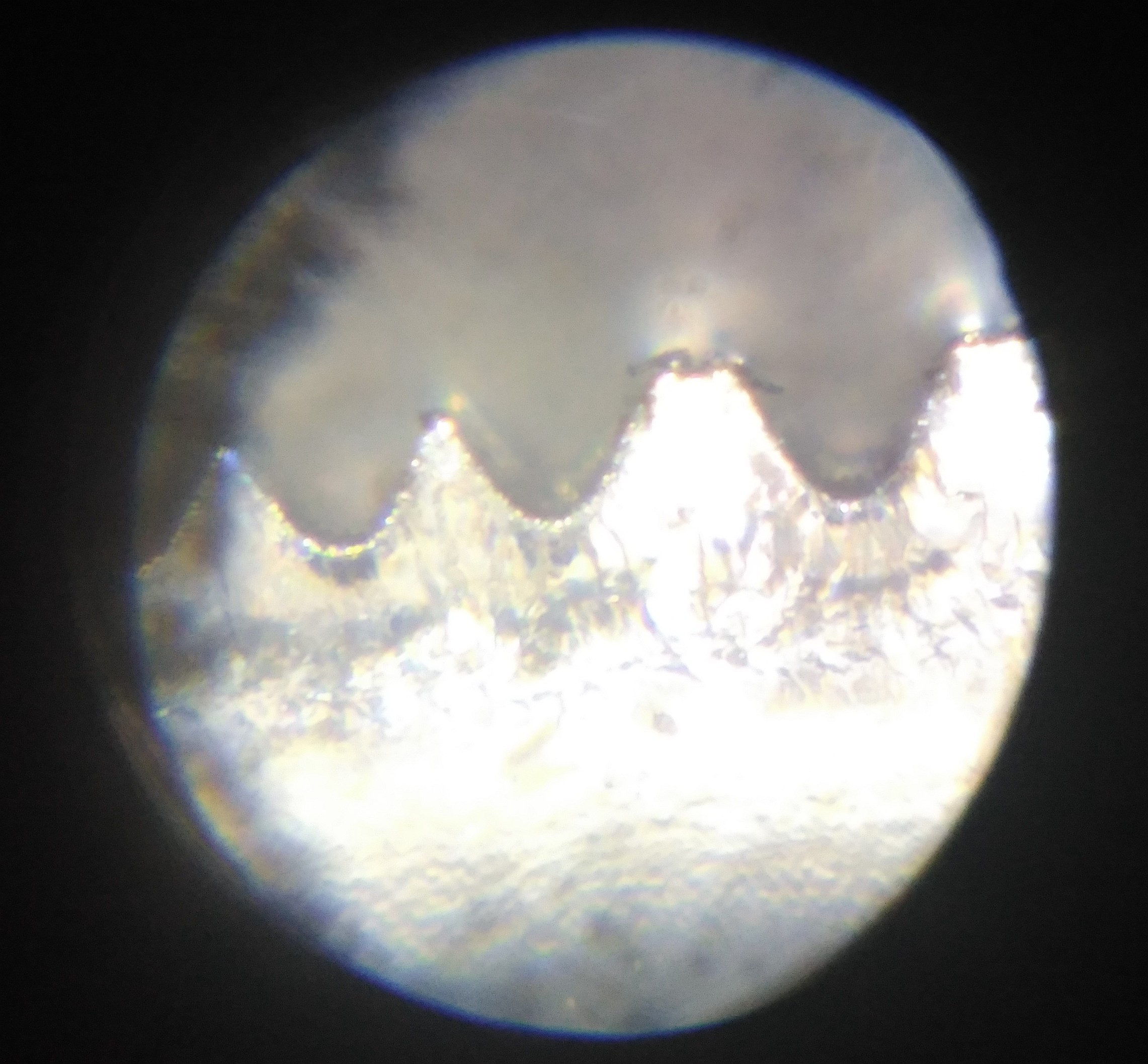
And here's what I saw:
![]()
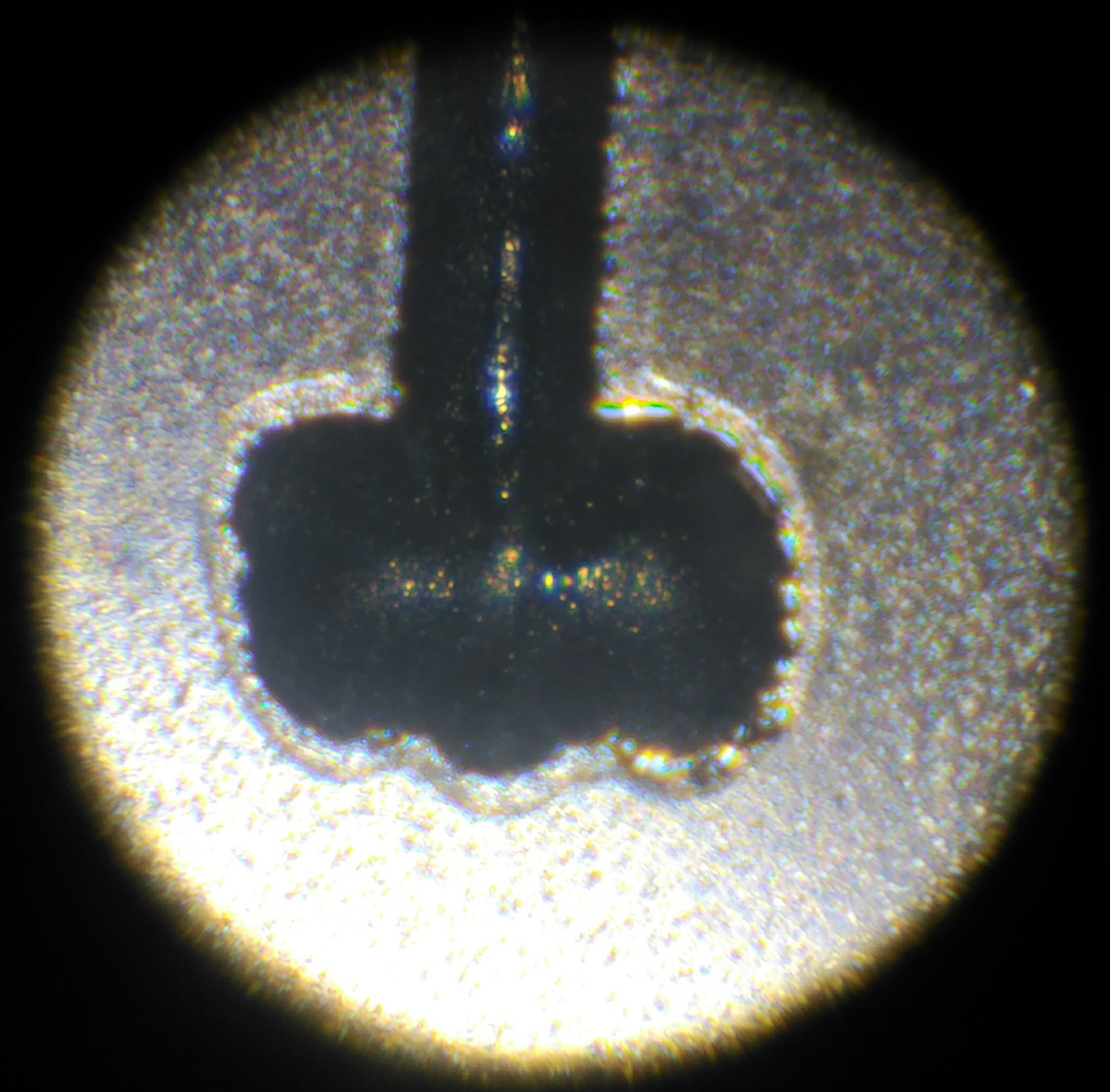
The trench etch looks fairly constant:
![]()
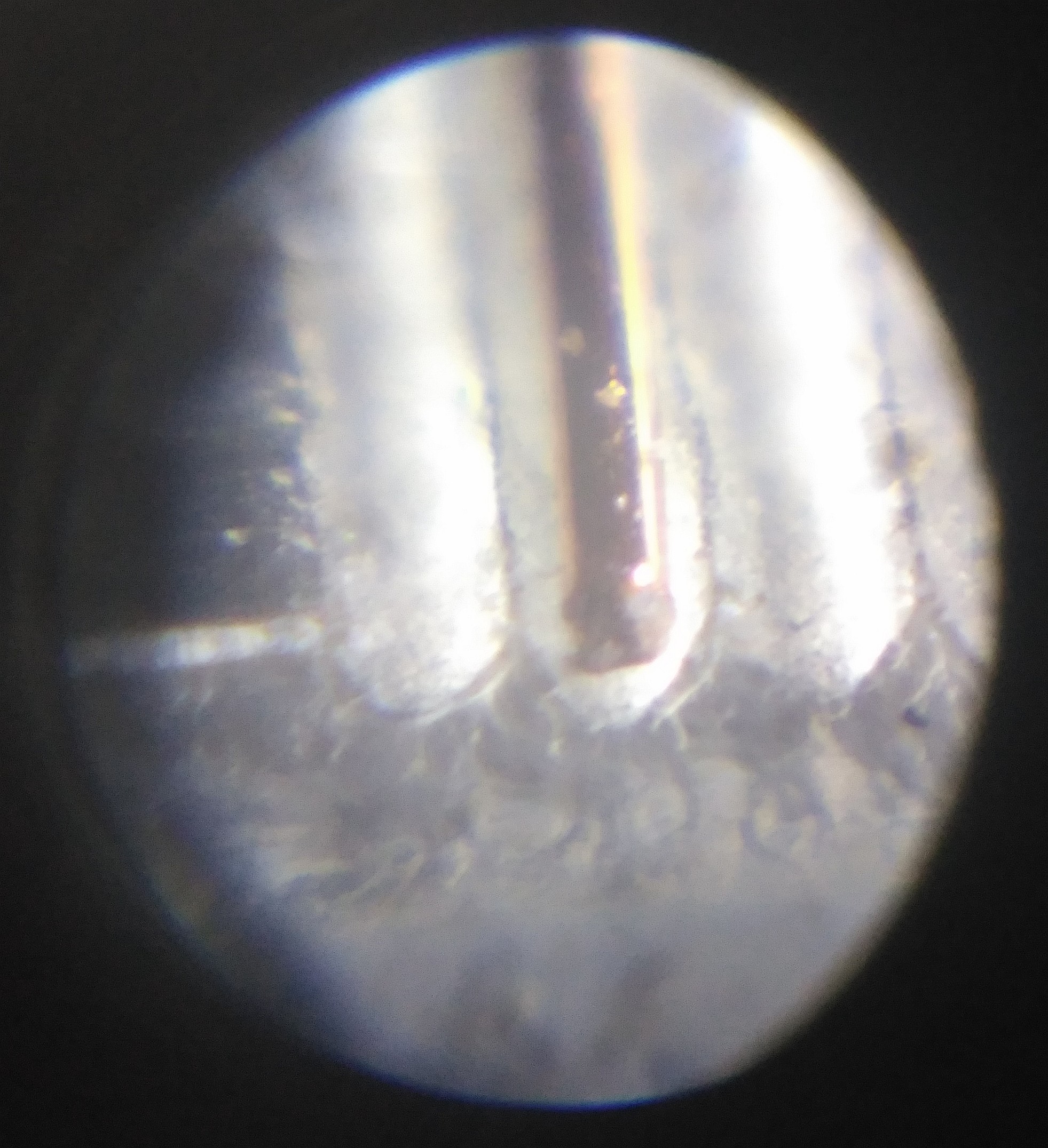
a 110µm copper wire for scale:
![]()
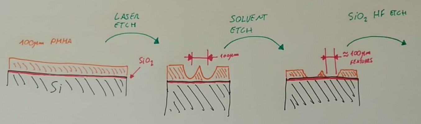
The plan is as follows:
![]()
You first etch the PMMA with the laser, but not trying to go all the way, just to the top of the silicon wafer. Then, using PMMA solvant, you eat away some thickness from the leftover PMMA, revealing the silicon on the bottom of the trenches.
After that, an anneal step and you can etch the wafer. This should enable 100µm features, with 100µm spacing.Wich frankly, is a really good start for me.
-
Under the Hood. (part 1)
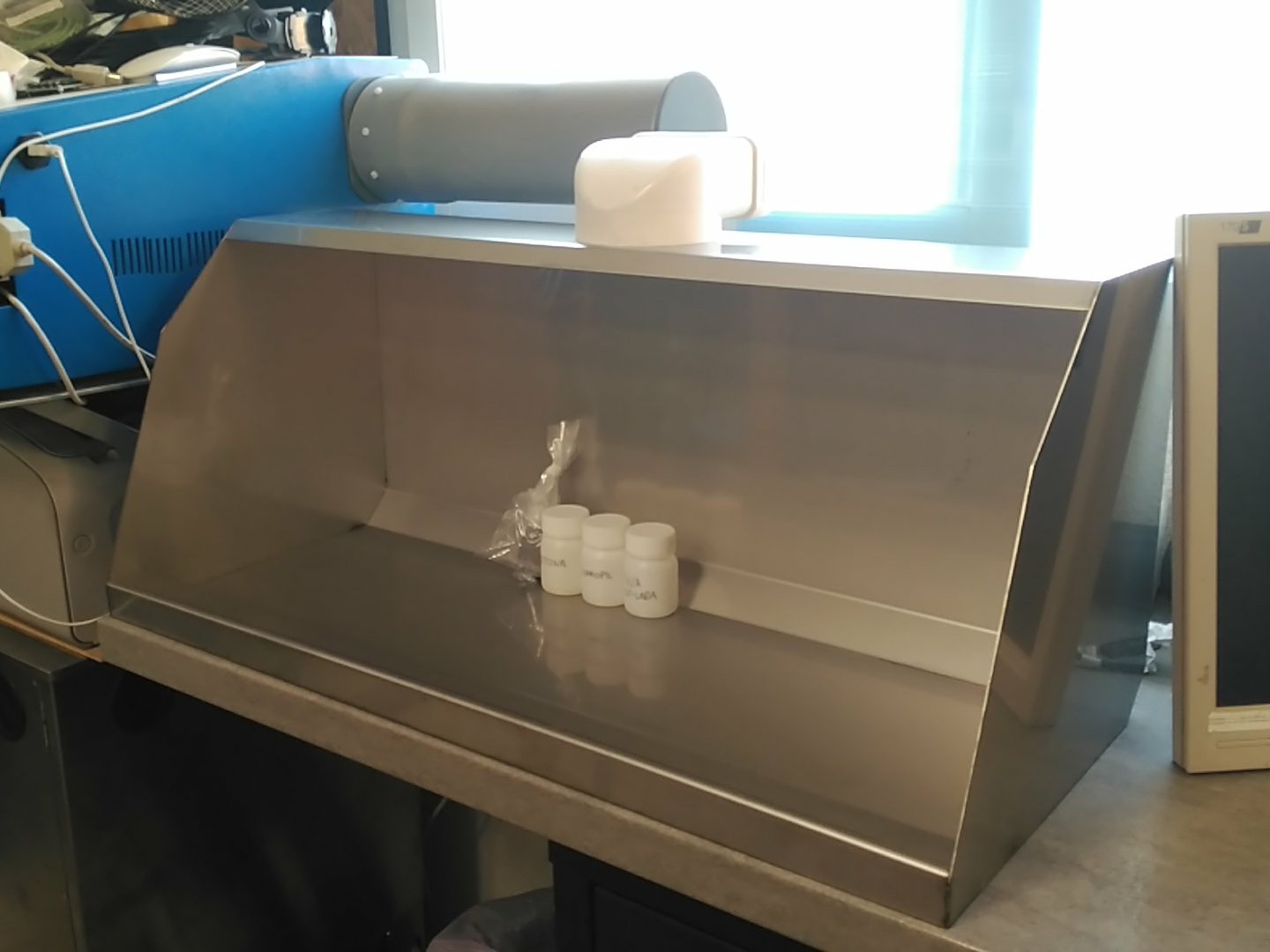
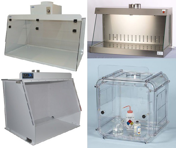
07/14/2018 at 10:16 • 0 commentsFinally, the fume hood is in the works!
I was unsure about what I wanted to do, so I sat in front of the computer and started to look into what the industry does.
![]()
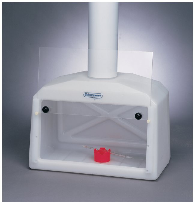
I also found complete molded HDPE fume hoods, wich look fantastic, and not super expensive (300ish €)
![]()
But in the end, anything I could make was bound to be cheaper.
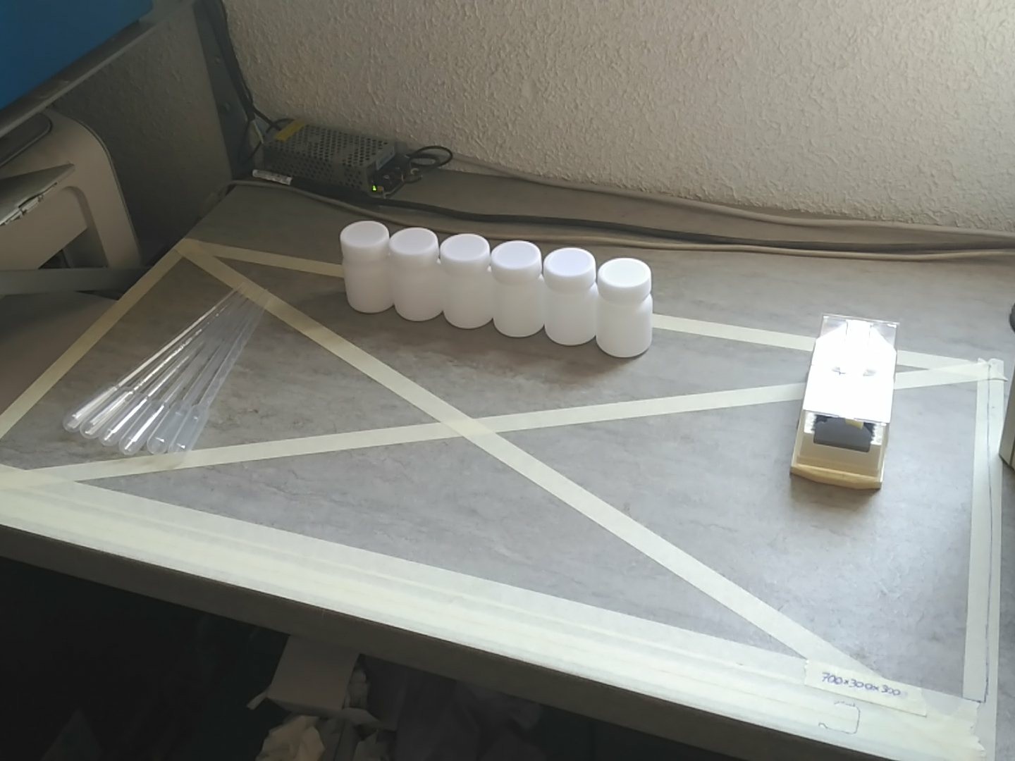
First I marked the avaliable space on the table.
70x30x30cm.
![]()
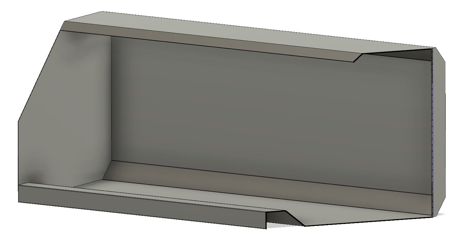
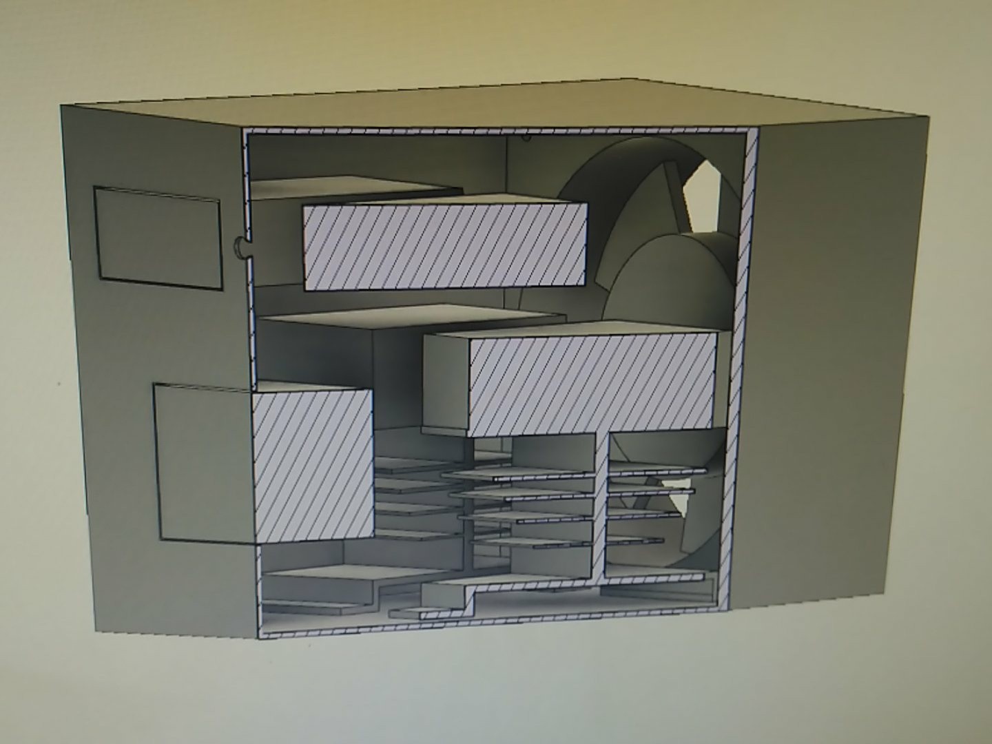
Once I clearly saw the boundaries, the design quickly came to my mind. It had to have a closed bottom so any small spills where contained, and be easily fabricated.
![]()
A simple C shape with 30mm height arm rest, and two side plates.
![]()
At first I thought I could half cut the sheet with an angle grinder and bend it by hand, but for 700mm width, that was not feasible, nor weldable with the experience I have.
After asking in a metal workshop, bending was so cheap, I opted to have it profesionally done instead.
![]()
Next time, finished hood!
-
Control Freak 2: Sidebox
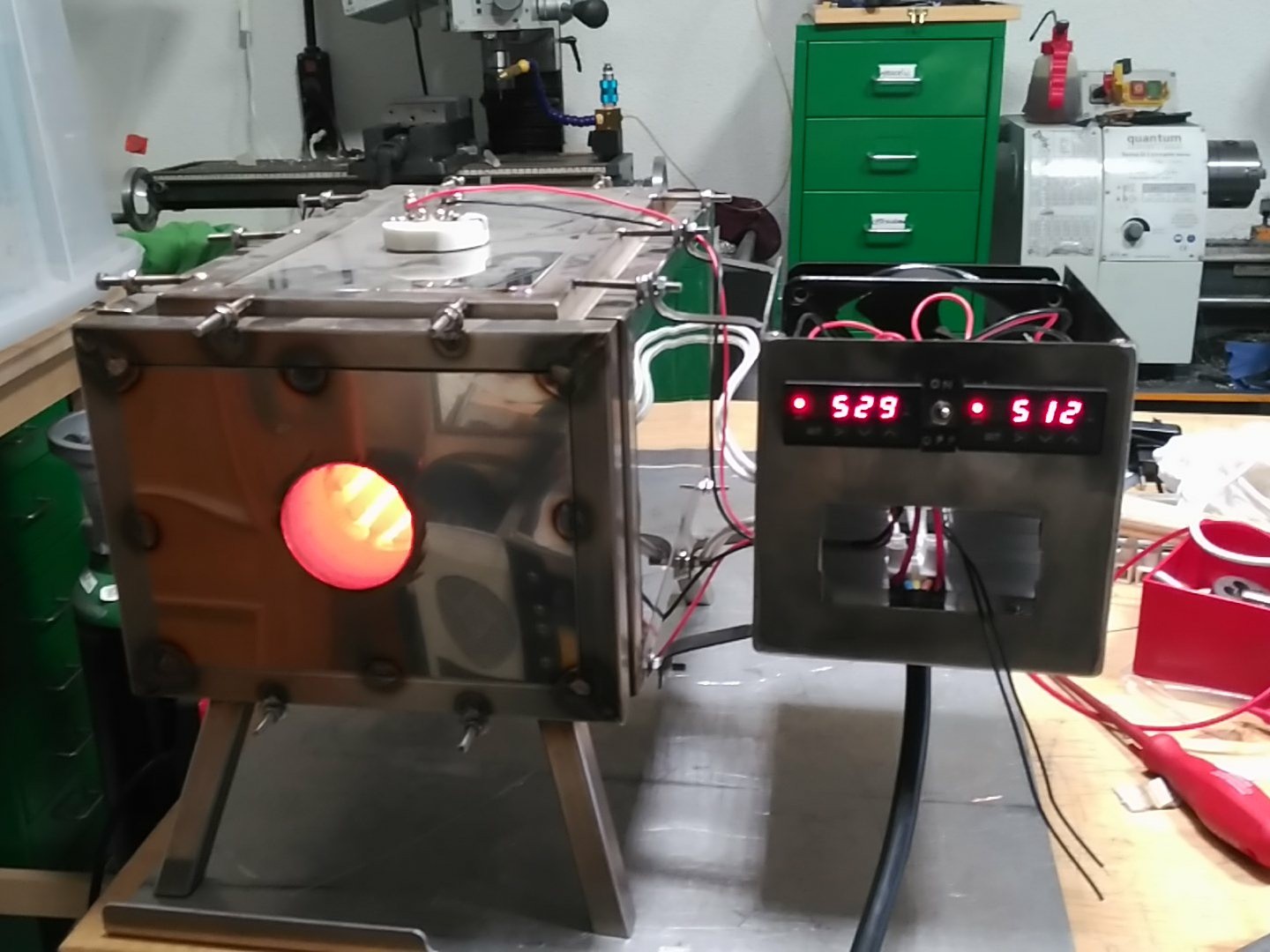
07/13/2018 at 21:58 • 0 commentsFinally!
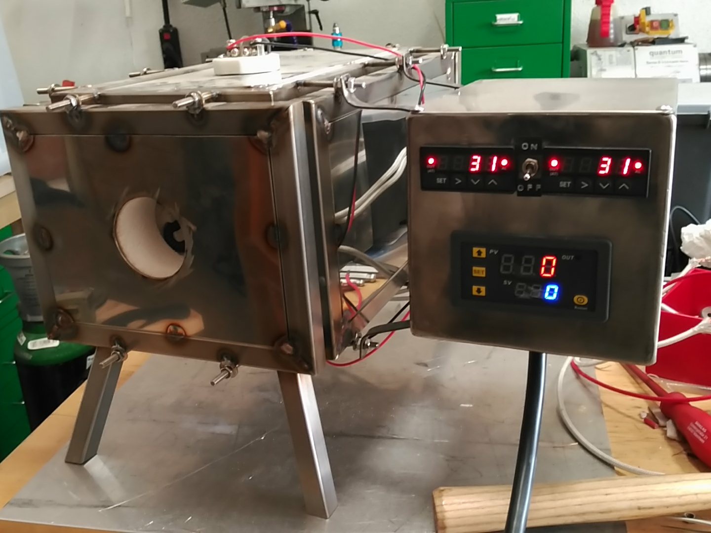
The oven controls got integrated with the main body!![]()
It features dual temperature controllers for top and bottom resistances + a timer for process control.
It also has the ability to disconnect the SSR's but still monitor the temperature of the oven.Build log:
A rough 3D model was made (in Fusion 360):
![]()
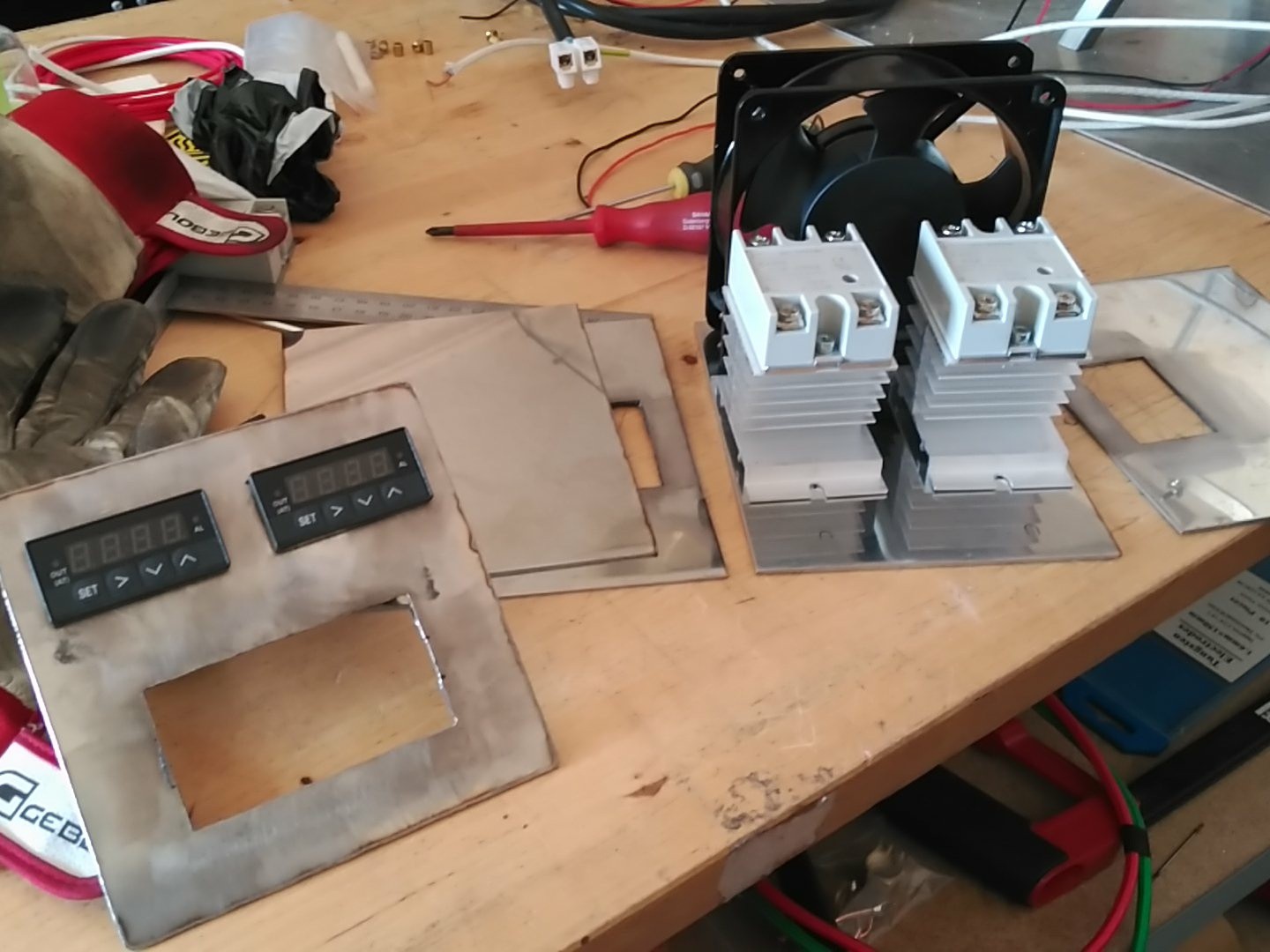
Then the panel CAD drawings where transfered and laser cut, and some panels made:
![]()
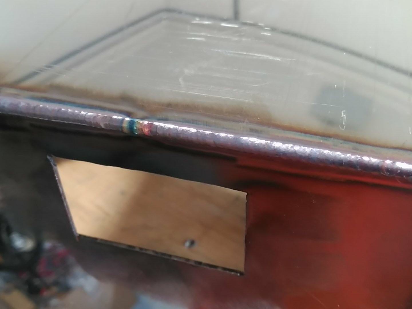
I'm slowly getting better with my TIG:
![]()
Dry fit, file, dry fit, add nuts:
![]()
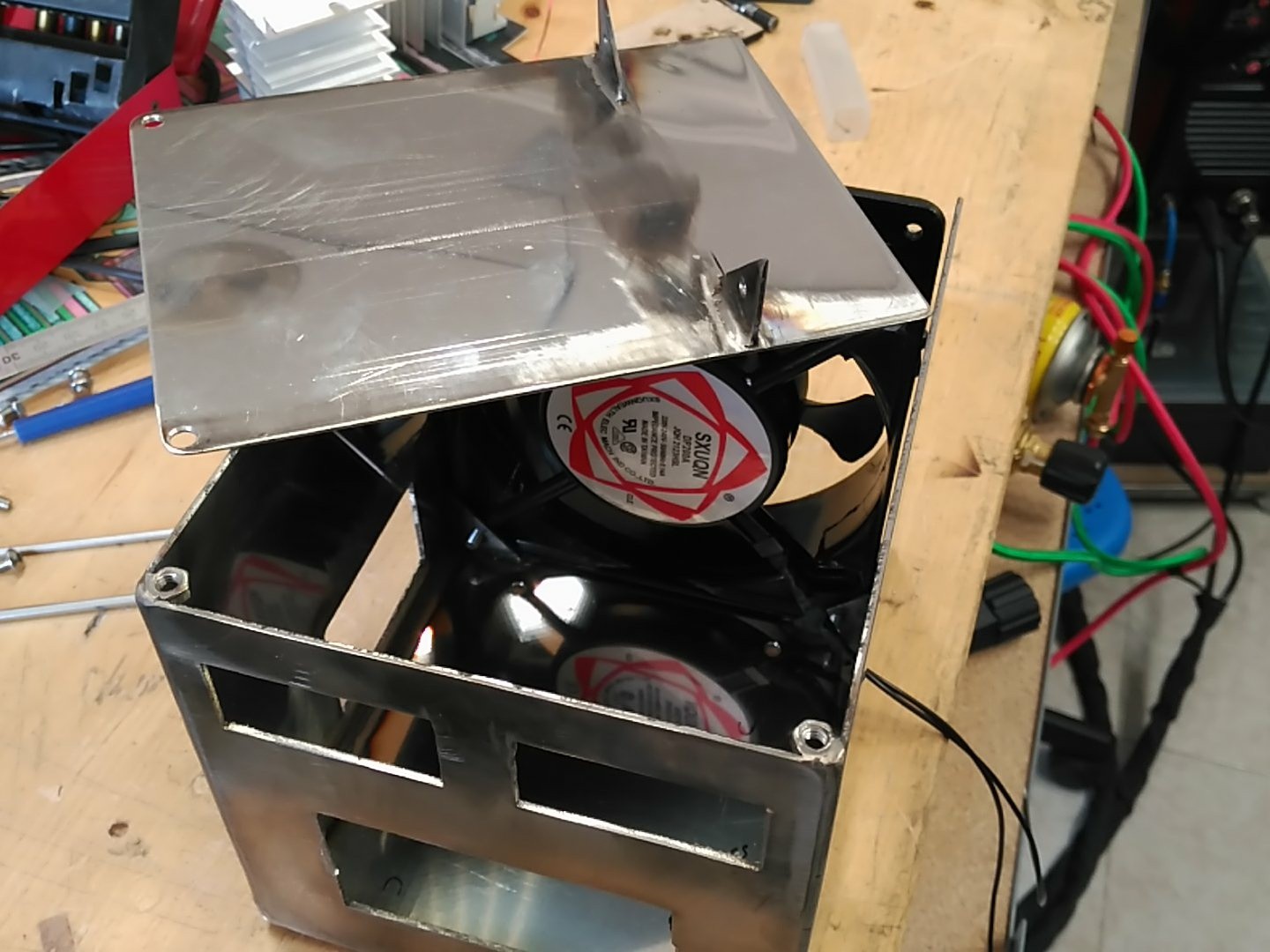
Add supports. At this point I'm too tired to care about the bends looking nice. XD!
![]()
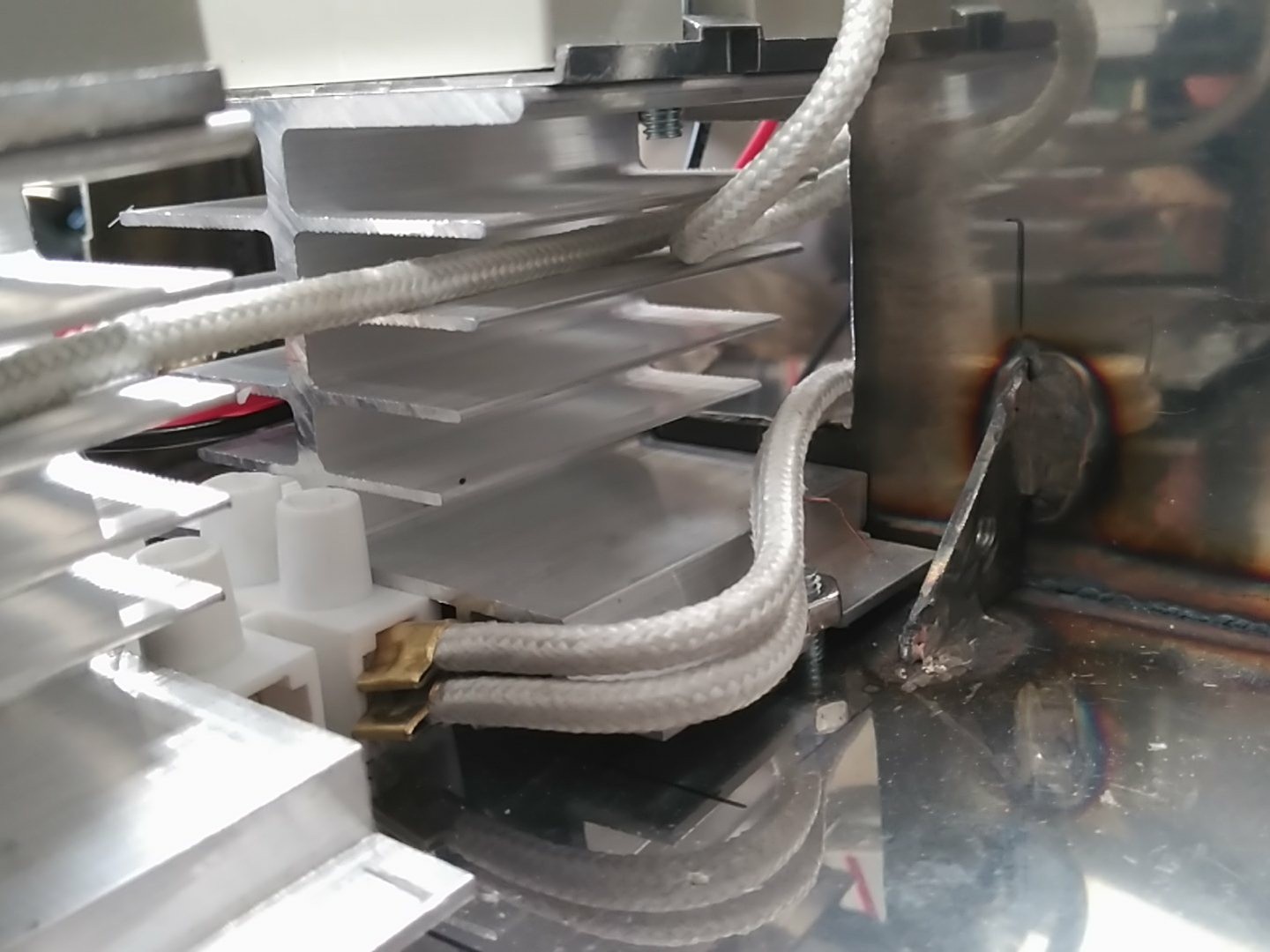
Power cable management:
![]()
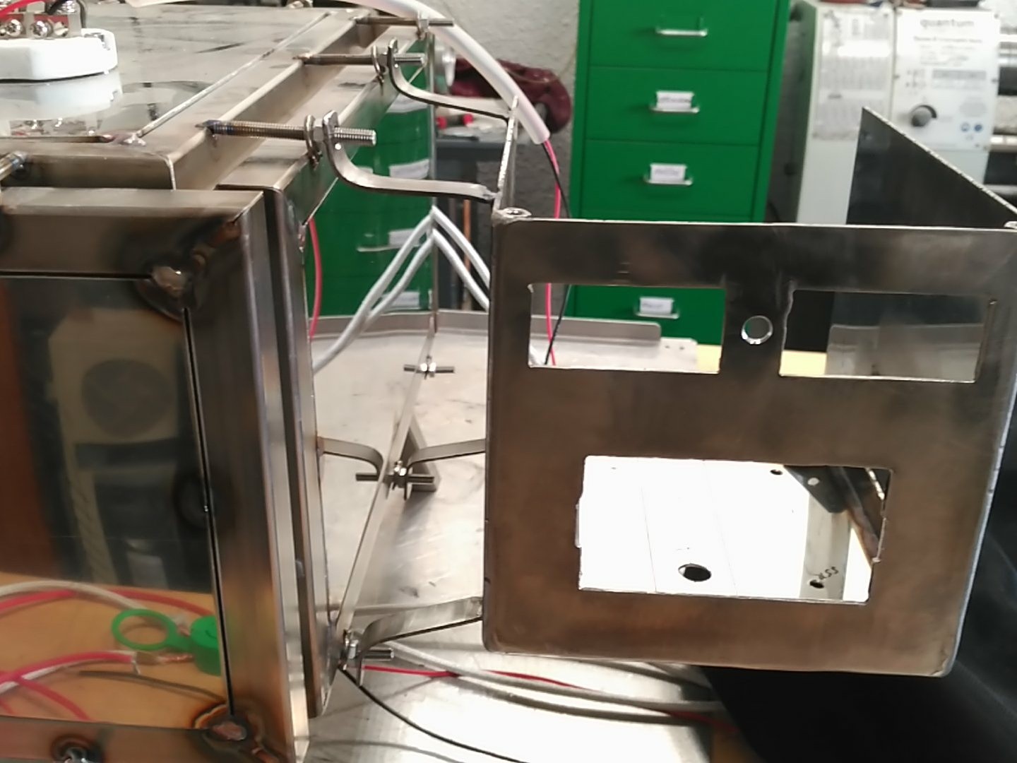
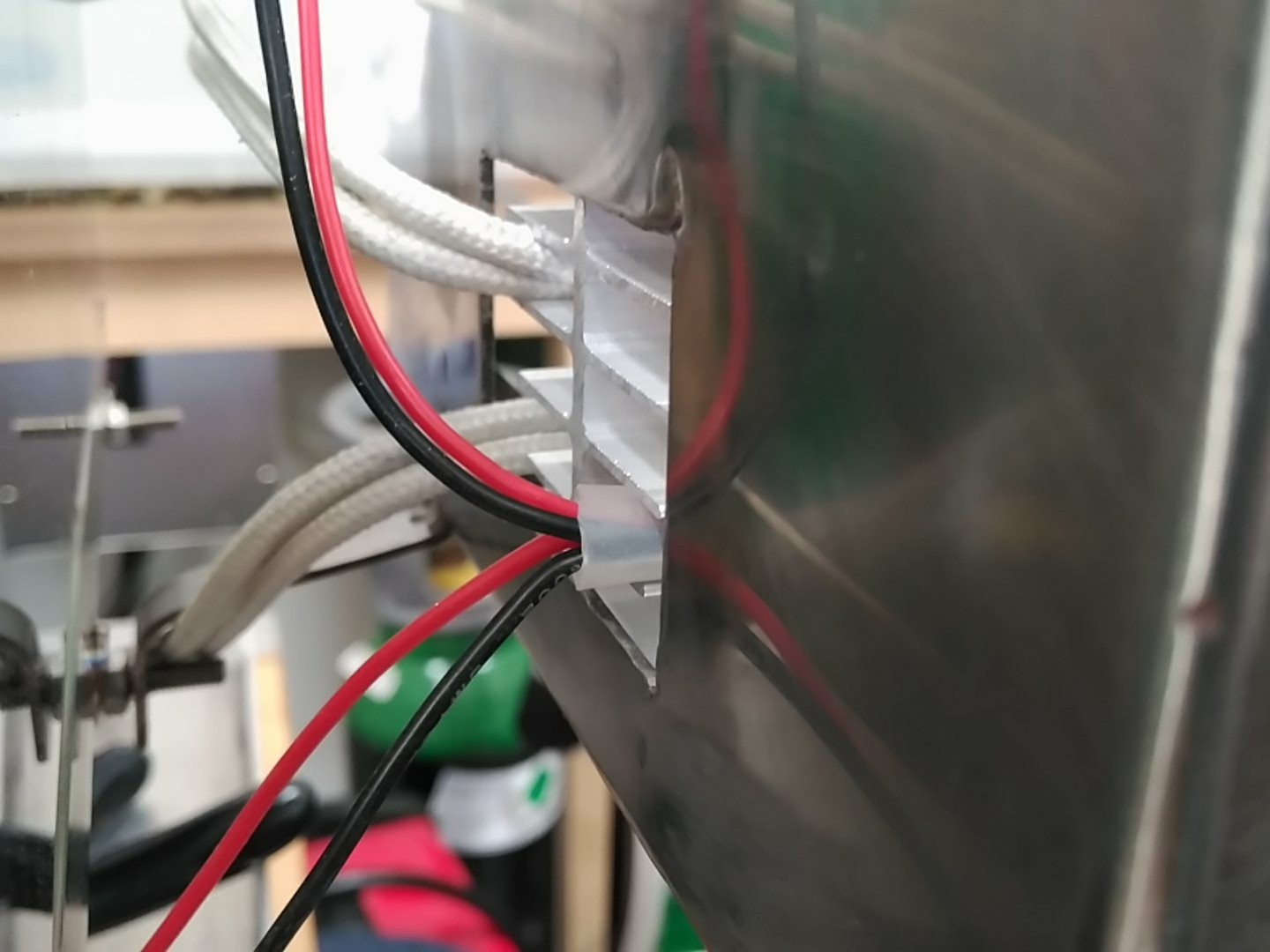
And exterior routing:
![]()
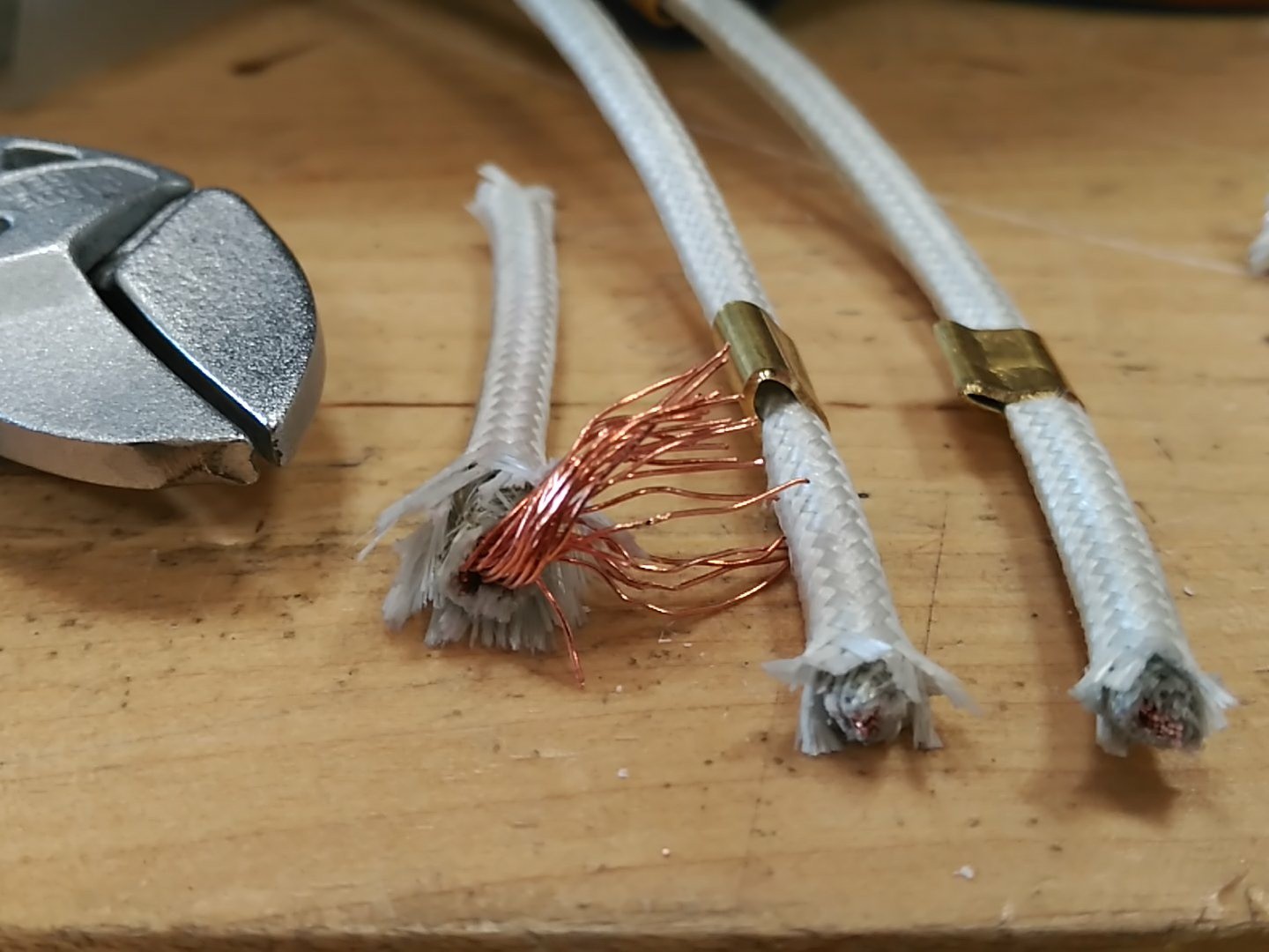
White cables are fiberglass triple insulated and the silicone tube is rated for 150ºC. Should I get to the point where that cable management fails, there are waaaaaay worse problems at hand.
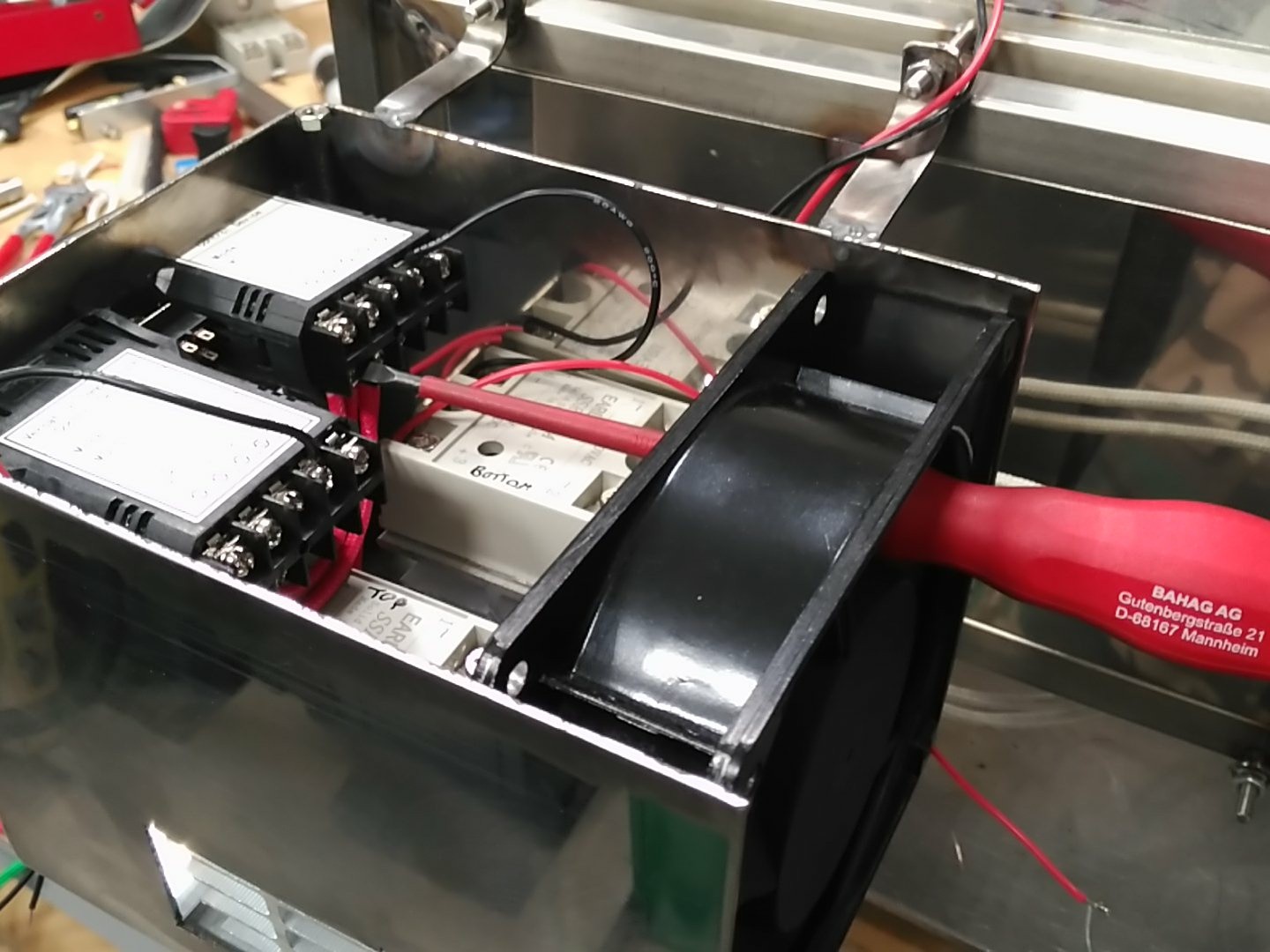
Also, when you want a compact unit, this kind of things happen:
![]()
Once the power section was finished, I gave it a quick try:
![]()
Everything looked good, so the timer was installed, and the box closed. (top image for final result). It does NOT have any control over the oven, it just buzzes when the time is up.
A quick note on the fiberglass reinforced cables.
Just peeling them off won't work, they will unravel and become dangerous. You must crimp them in some form. I just happened to have some brass tube and crimped it's side with parallel pliers.
Leave some millimeters after the crimp before cutting the protection.![]()
See ya!
-
Control Freak.
07/05/2018 at 16:54 • 0 commentsFinally got a plasma cutter so I could work sheet metal and make the fume hood to work with the nasty chemicals required.
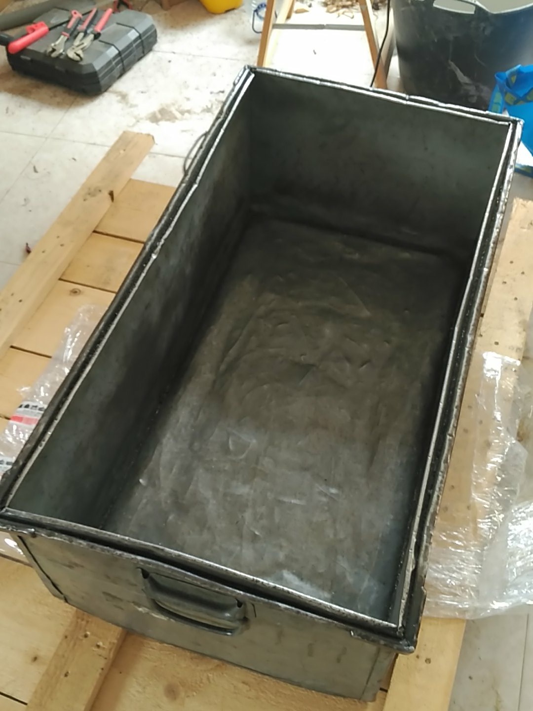
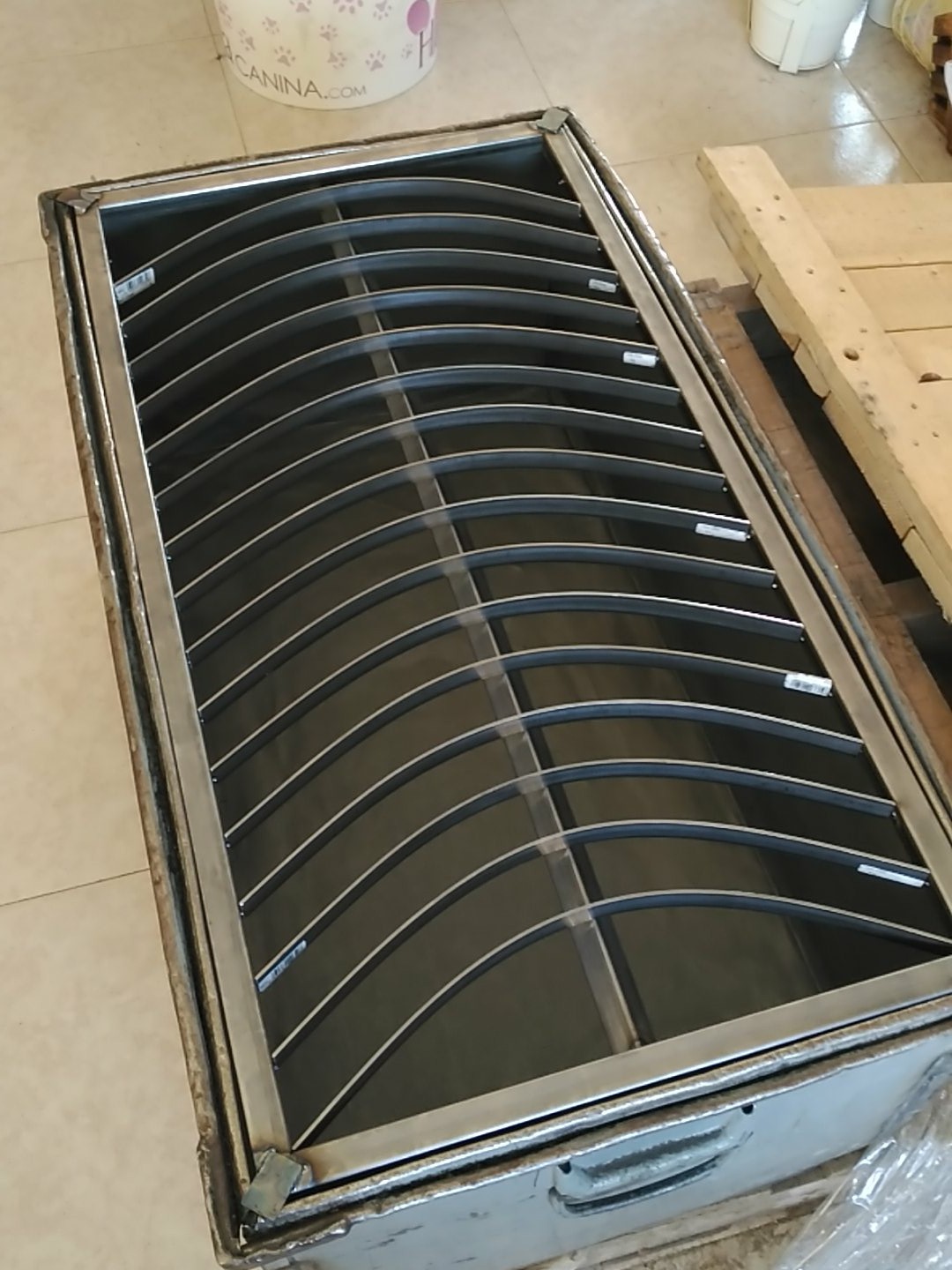
Plasma cutting is relatively easy, however, unless you have a very good worksop, it requires some way to contain the sparks it produces, so I had to build a water bath and cut support.
A secondhand metal box was bought:
![]()
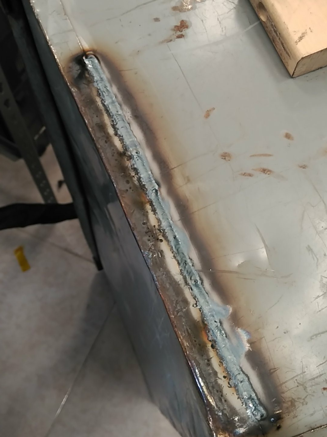
And welded shut because the ends where just spot welded.
![]()
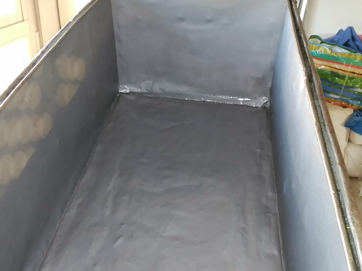
Painted it with anti rust paint:
![]()
The cut support was made to fit inside the box and have removable blades:
![]()
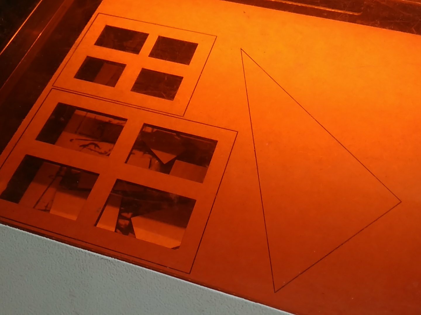
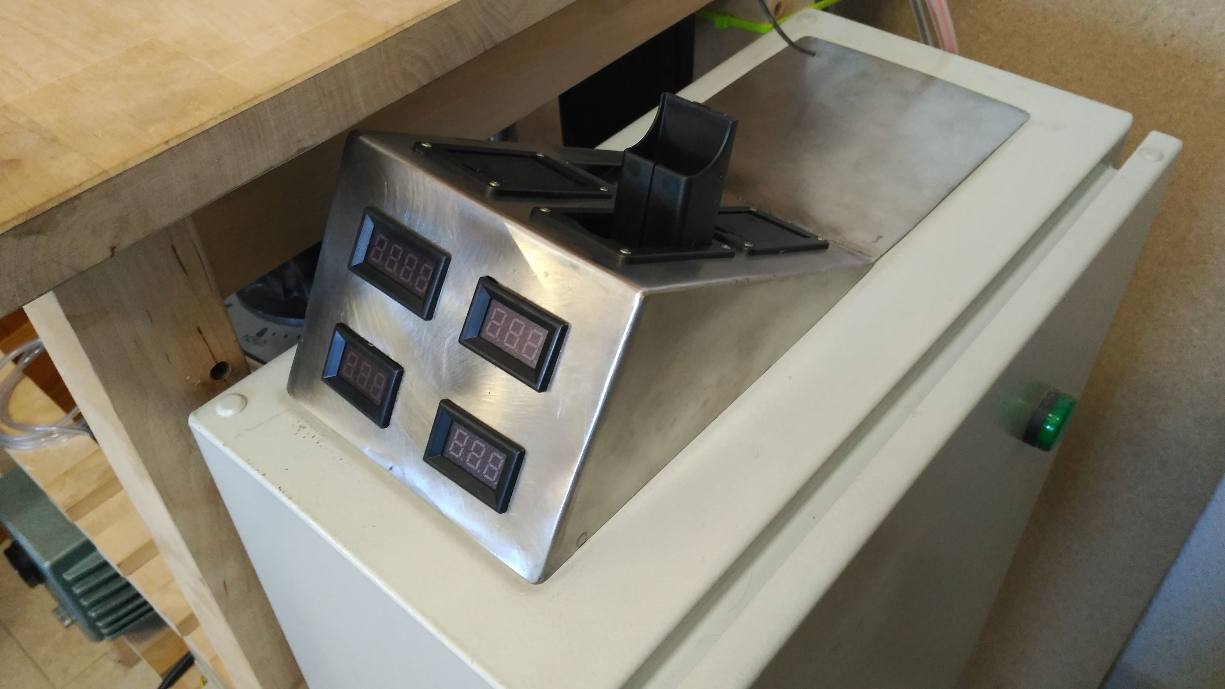
As first project, I made a monitor panel for the sputtering machine.
Good thing about plasma cutting, is that you can make wood templates, and so I lasercut some:
![]()
You must remember to adjust for the kerf and nozzle width (for my cutter it's 3.375mm/r (1mm kerf)
![]()
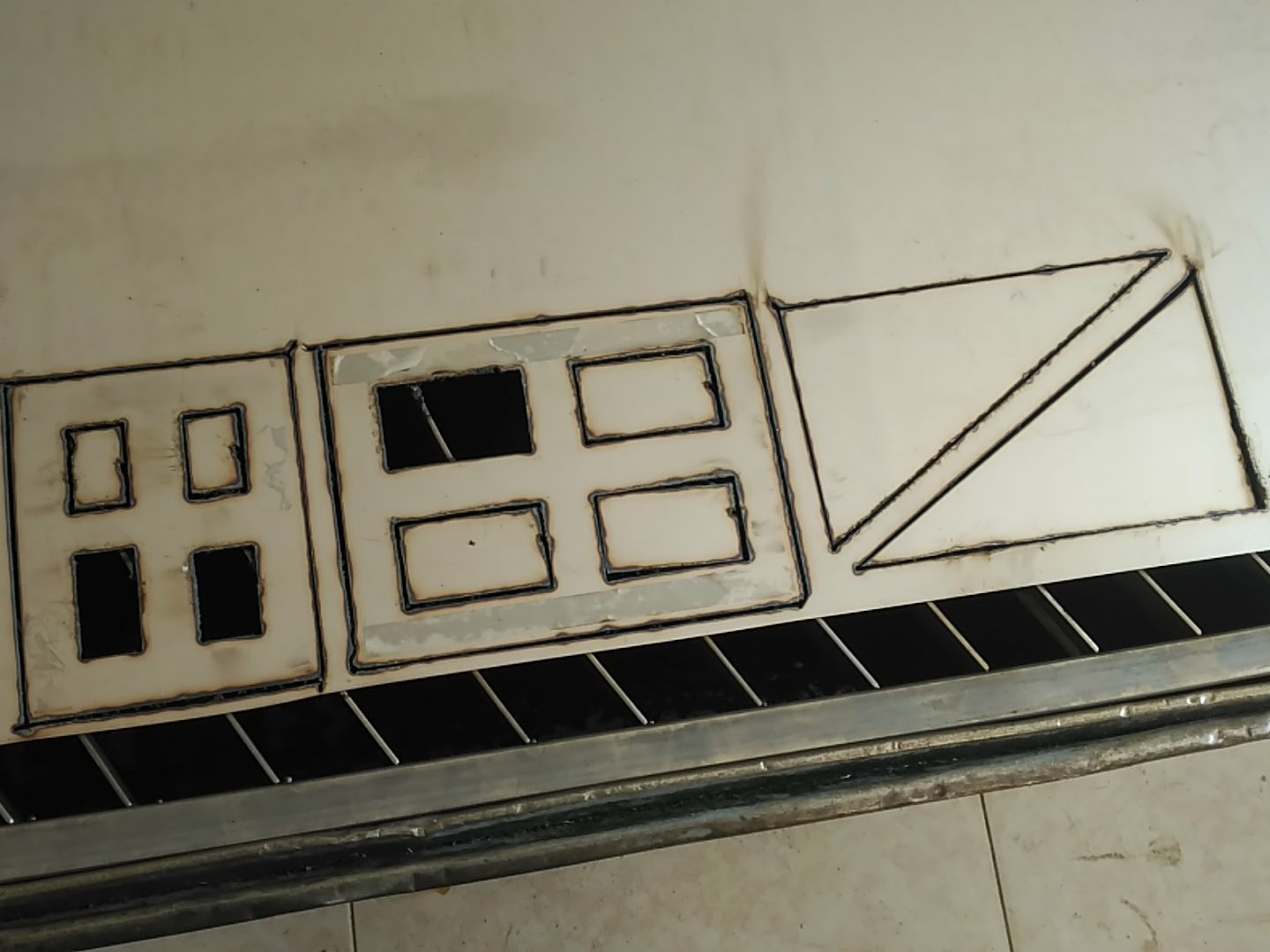
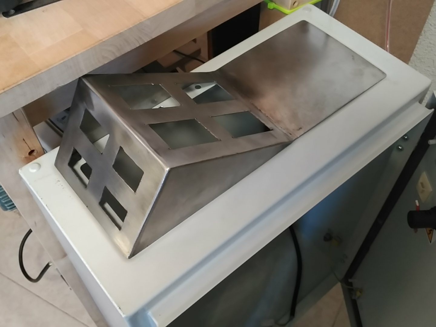
I have much to learn on plasma cutting, so this was not perfect, but should work.
![]()
Since this uses high voltage and I didn't want to have weird feedback loops between the instruments, I installed separate battery holders for each one. They are 9V flip-ups from guitar equipment.
![]()
-
You can't cheat physics...{e-beam litography @ home, part 1(the fail)}
06/26/2018 at 14:17 • 0 comments...me neither!
Where have I been? Up to no good, apparently.
So, I have this weir idea to use acrylic (PMMA) as masking, because it is convenient and readily avaliable, however, to do photolitography with it, you need an electron beam...sooo, where do you get one?
Unlike some countries, in mine, there are no electron microscopes readily avaliable for cheap prices, so I had to look for an alternative source of a focused e-beam.
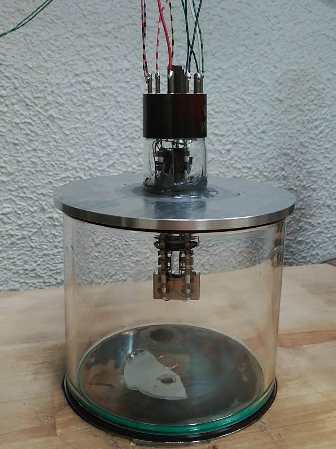
![]()
Yup, that's an oscilloscope CRT pointing inwards to the vacuum chamber.
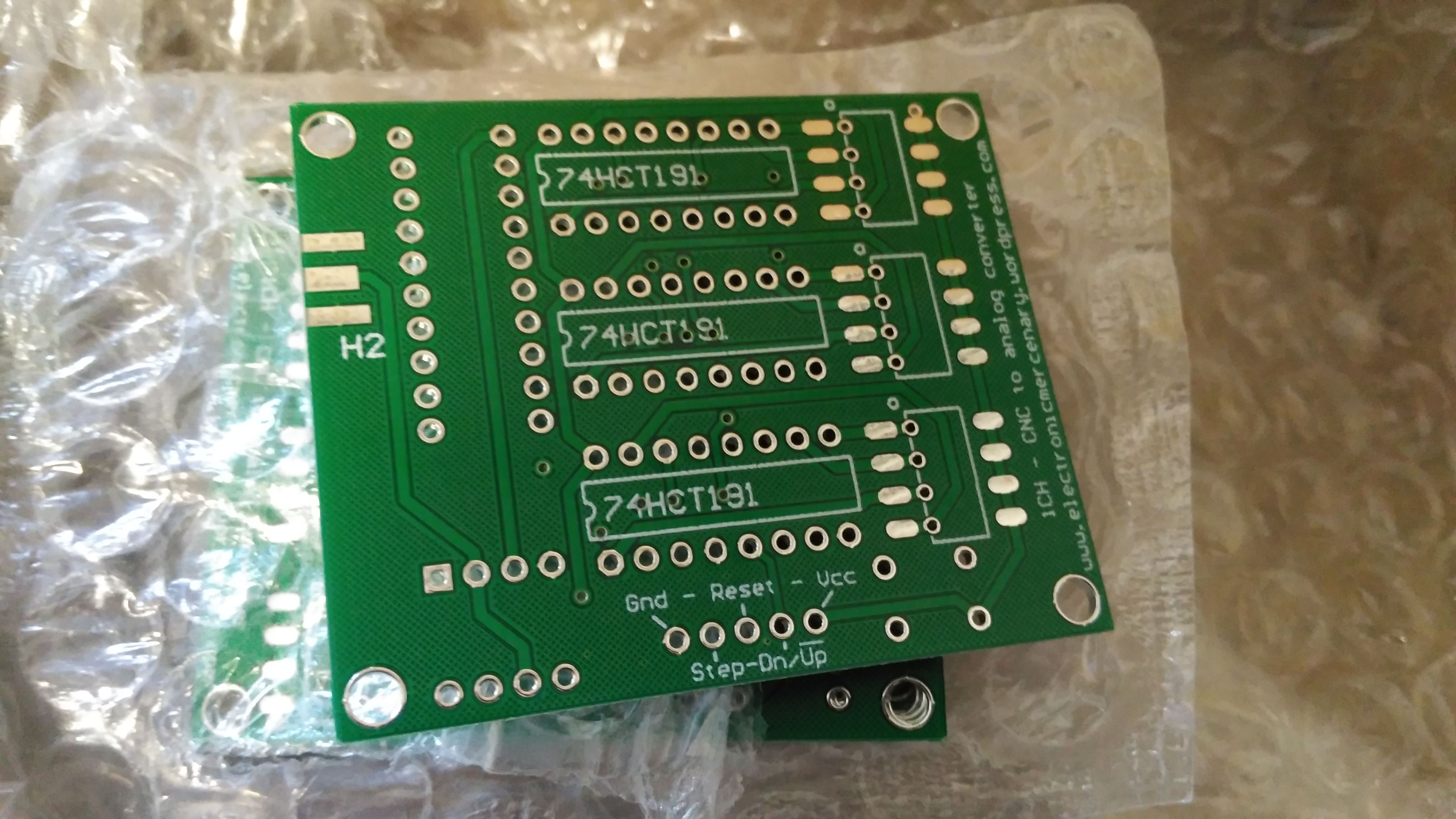
For control I made a CNC to analog board:
![]()
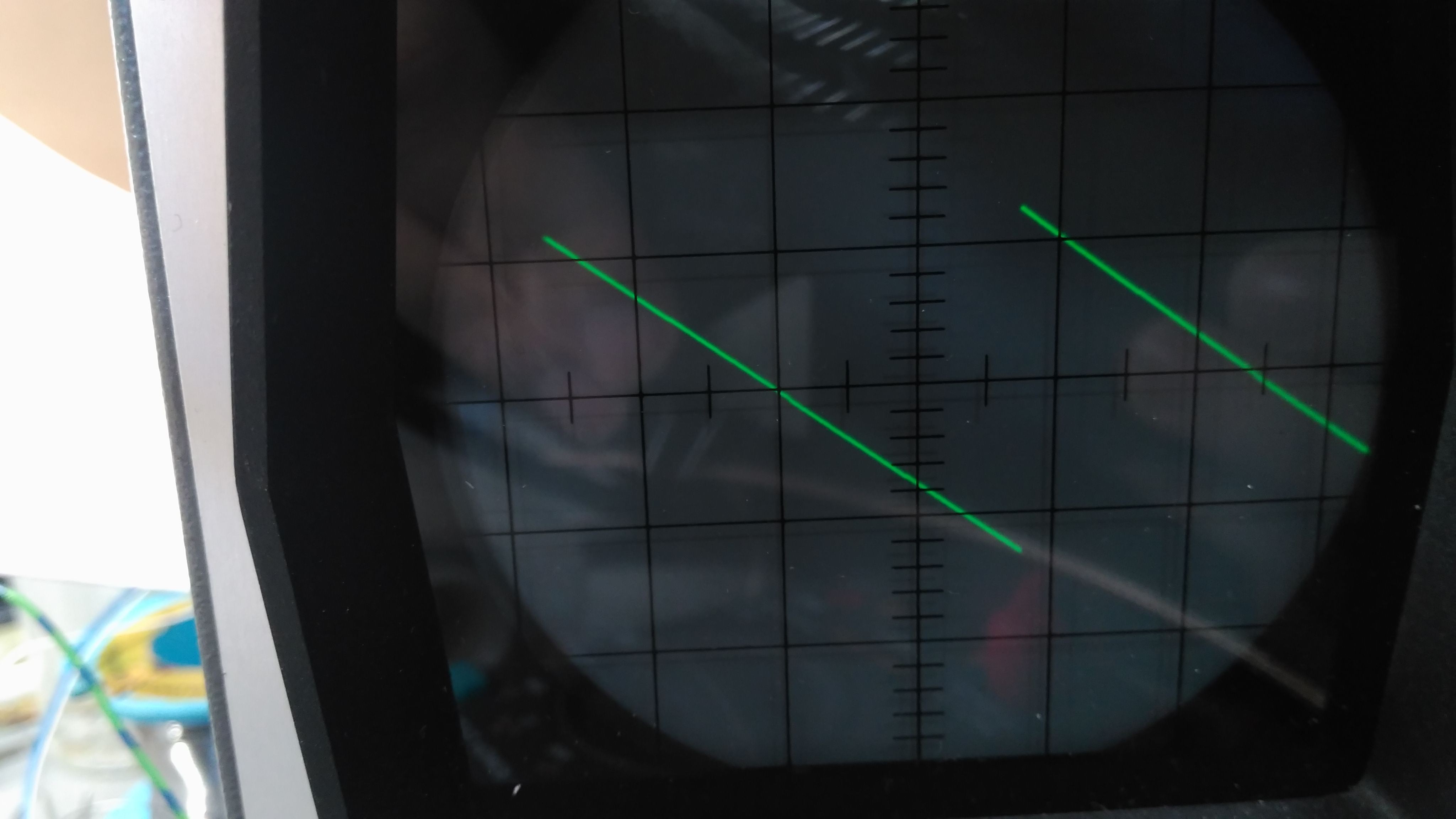
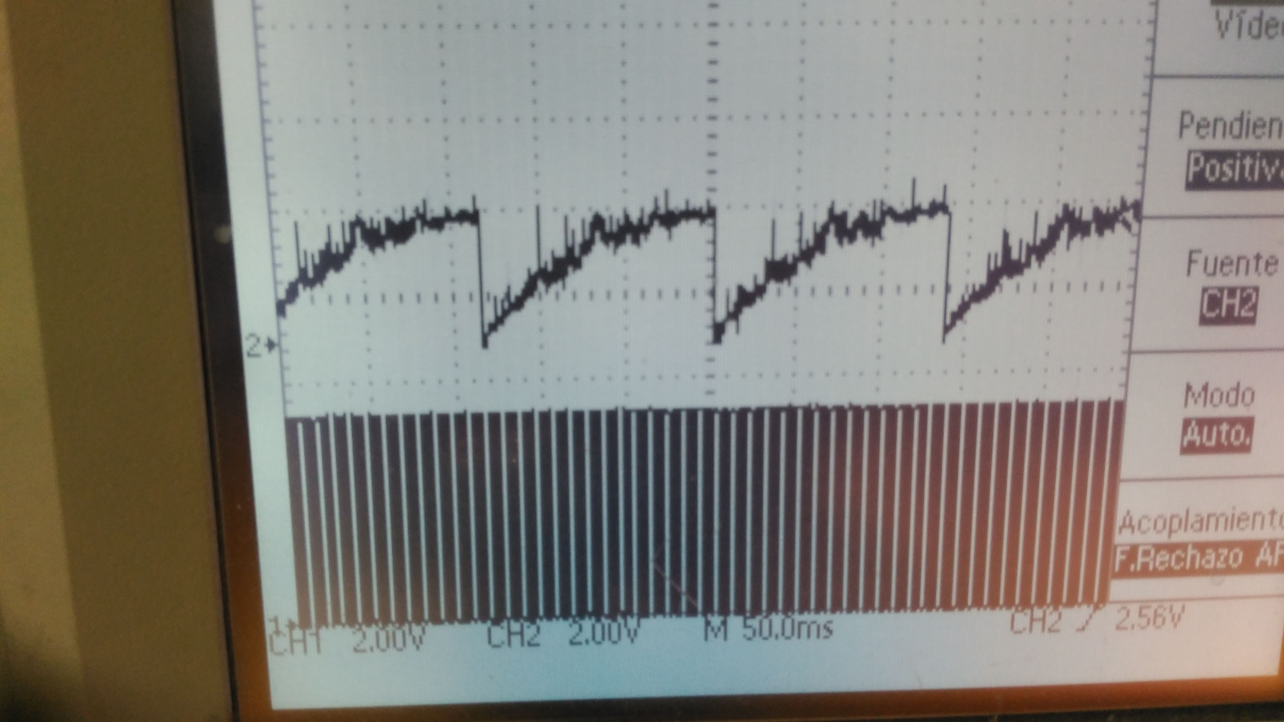
Using 3 up/down 4 bit counters to get the step and direction lines from my laser cutter software and using a DAC to have an analog value that the oscilloscope electronics could use. However, I had problems with the integrated DAC, wich was noisy as hell during switching:
![]()
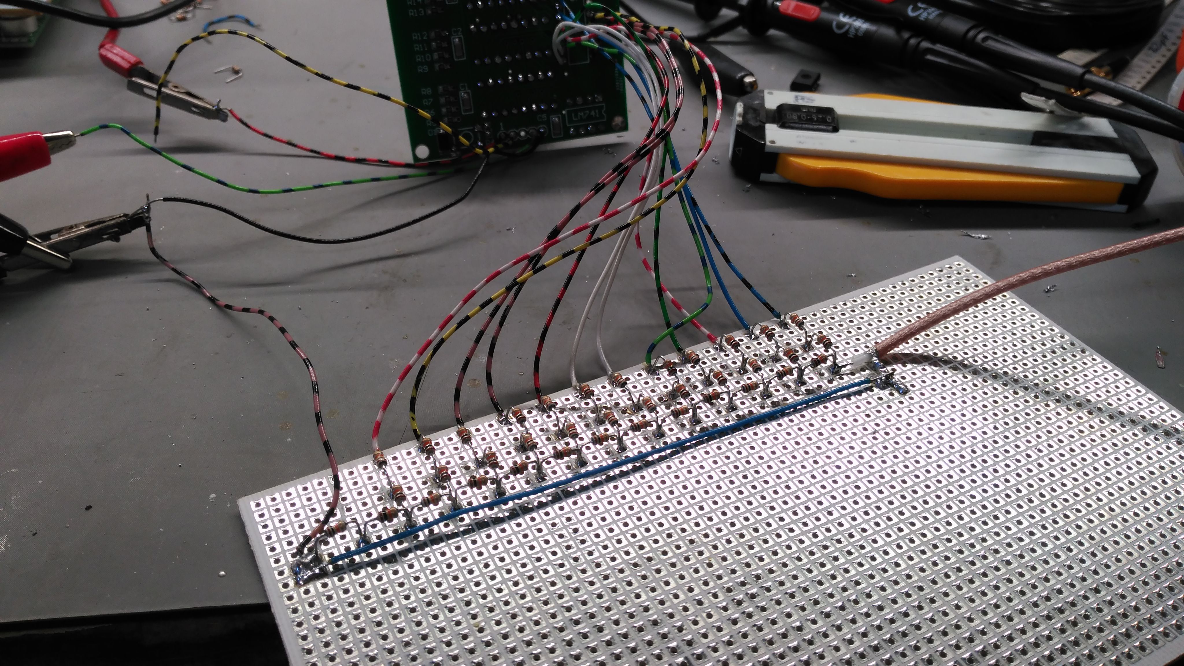
And had to resort to making my own R-2R ladder.
![]() It was done with 5% resistors, just for the heck of it, and it is pointless as is, but I had a bag of them, so, no regrets.
It was done with 5% resistors, just for the heck of it, and it is pointless as is, but I had a bag of them, so, no regrets.
Anyhow, the performance, side by side, was much better:![]()
I implemented two of them (hacked the blanking too) and had some fun:
(long exposure shot):
![]()
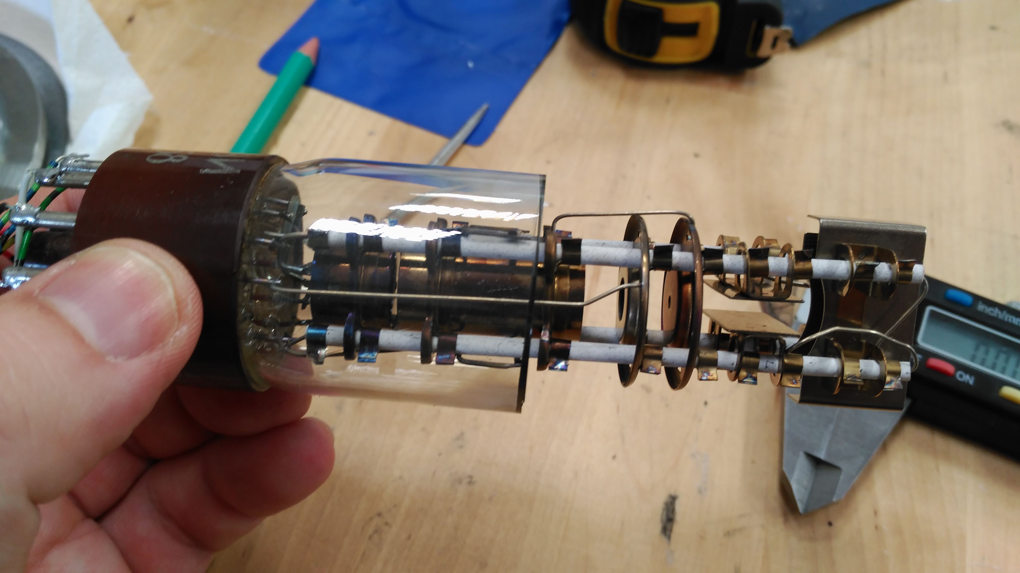
Originally I had planned to drill the front of the tube with this vacuum setup, and use it as is.
![]()
However, after five hours of trying to drill it dry I had only gone just half the glass, and decided it was worthless.
![]()
So I broke the vacuum with a small diamond drill and then cut the tube. It took a few trials to get a clean cut, so I ended with a short stub:
![]()
As you saw in the first photo, I glued it to a machined plate and sat it in the vacuum chamber.
In the end, I decided to try to start the tube with only the mechanical vacuum pump. I had a small hope that it would be inefficient, but work to some extent, however, 30/50 microns is still too high of a vacuum to properly run a CRT tube, and plasma discharge started right away.
Since I was pretty sure this was going to happen, I did record it in slow motion, to capture more details, fail starts @ 0:25
Also I already had bought parts to build an oil diffusion pump:
![]()
![]()
Unfortunately, I overestimated how low my TIG welder could go, and at it's lowest setting, pierced the thin 0,25mm stainless sheet. Rendering all pieces unusable.
Having to spend more money on this, and having just met someone who could help, I decided to try to obtain a turbomolecular pump.
Semiconductors @ Home
Building all the tools neccesary to make chips at home.
 There!
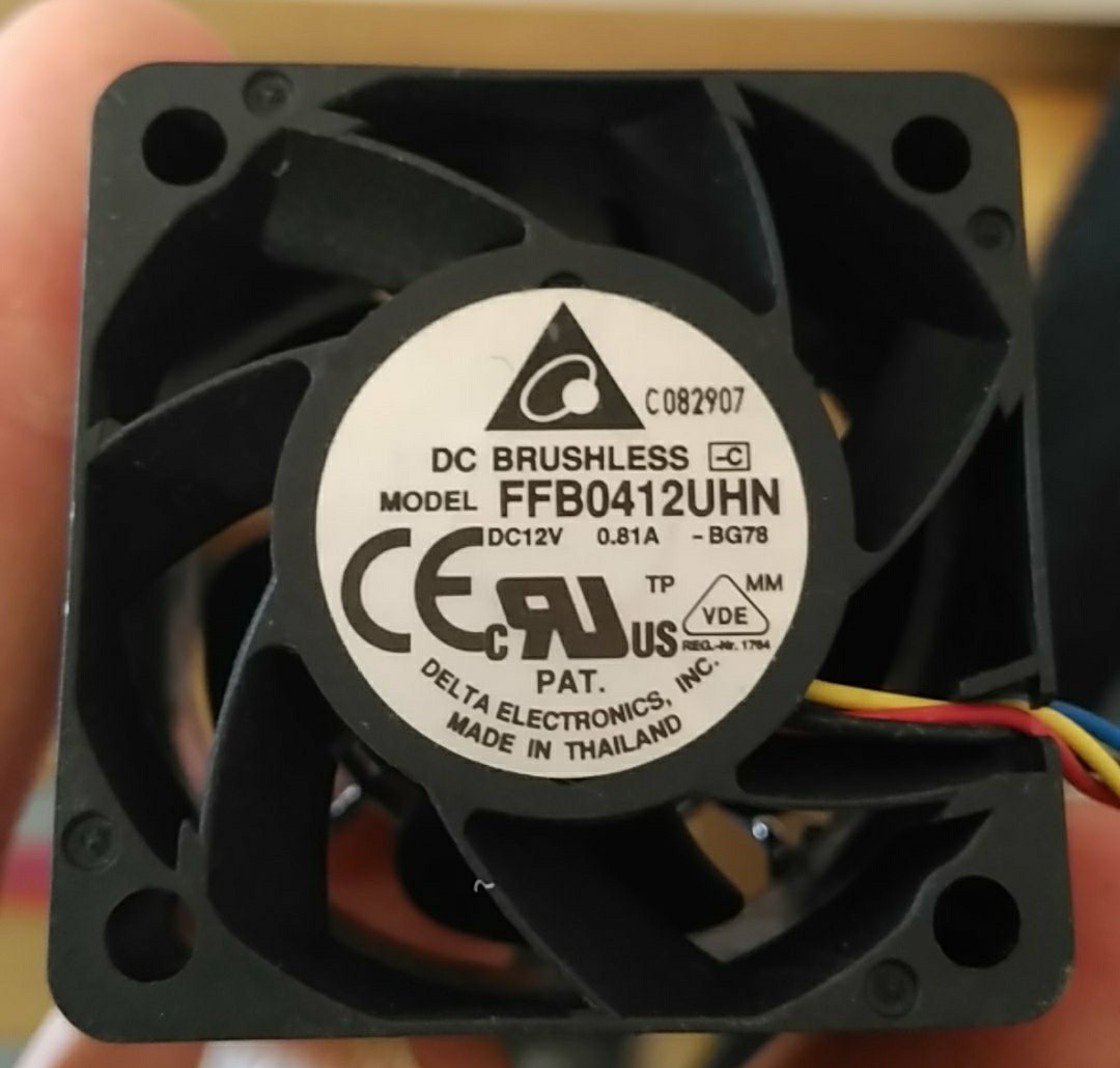

 On top: Beam backward tracing with a flashlight so I can position the graphite block.
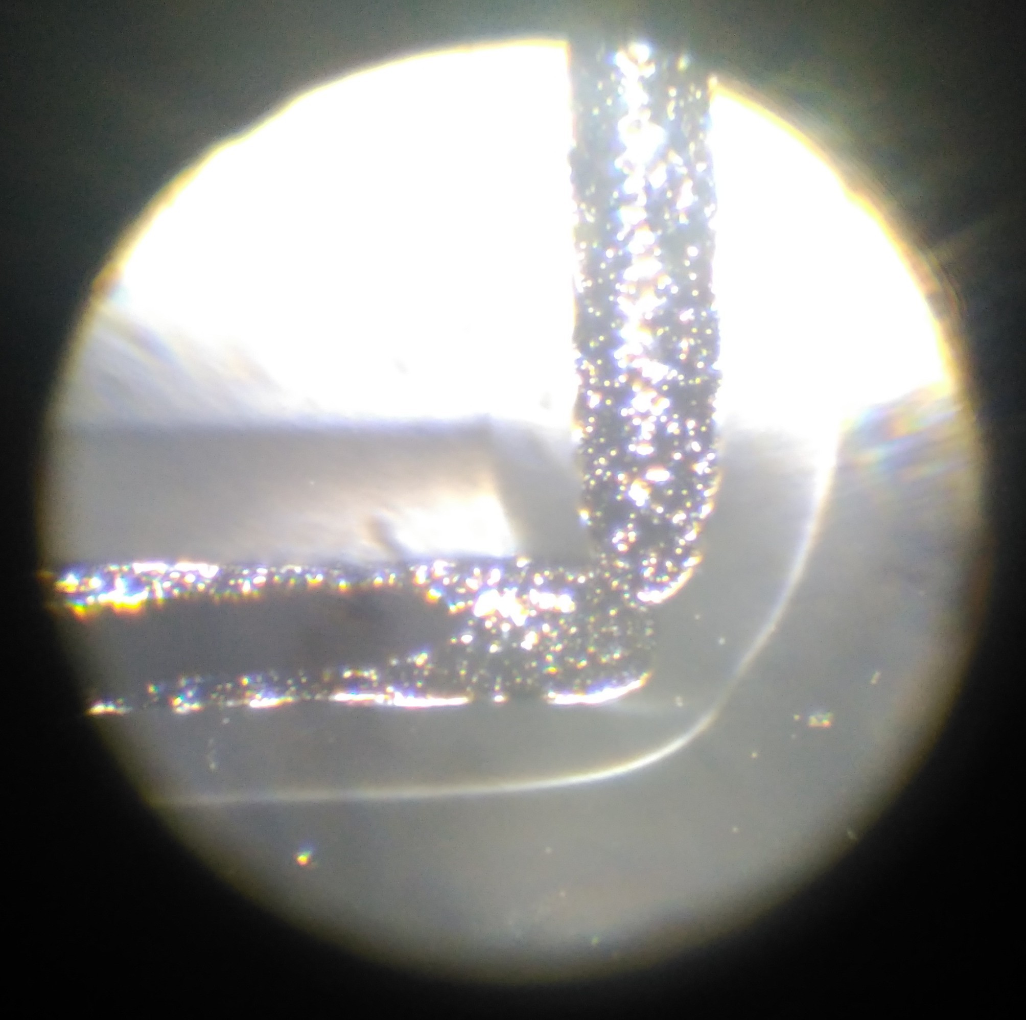


 It was done with 5% resistors, just for the heck of it, and it is pointless as is, but I had a bag of them, so, no regrets.