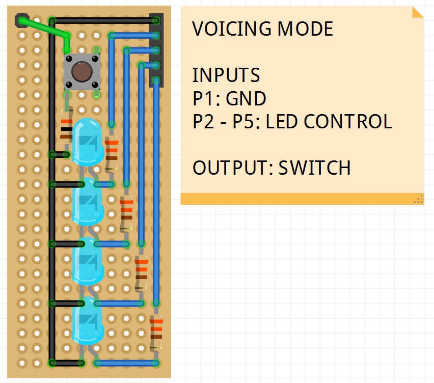
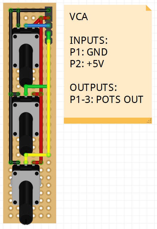
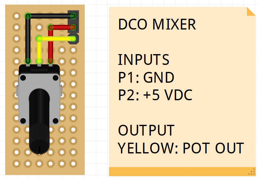
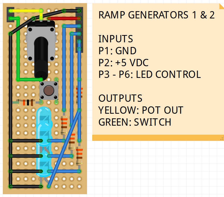
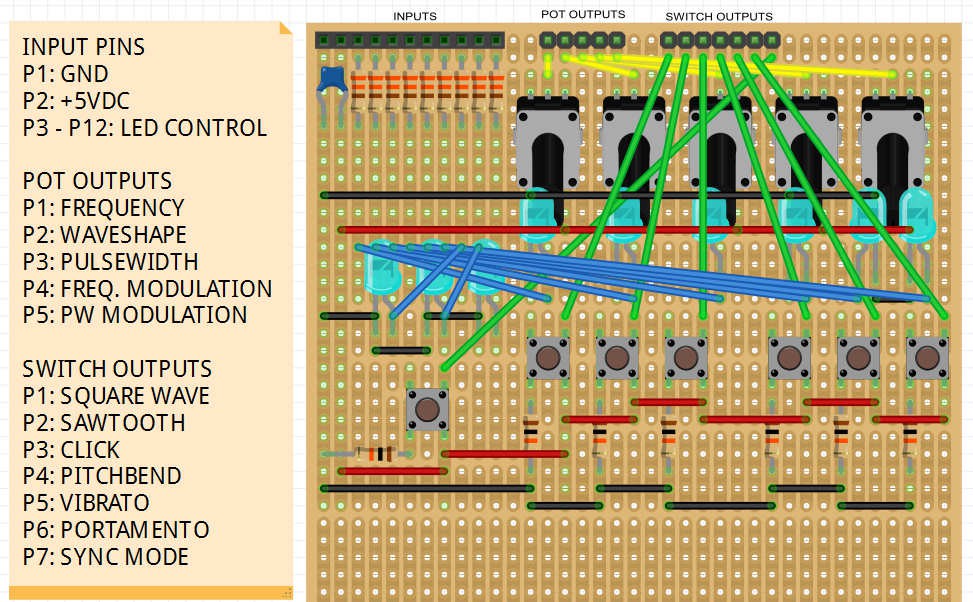
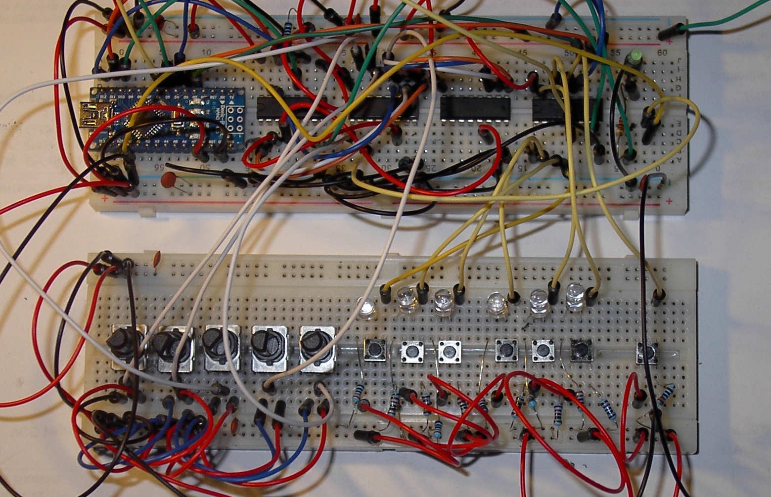
The heart of the controller will be an Arduino Mega 2560 because I need the extra IO pins and I'll never be able to fit the program code in just 30 Kb. All user input will be done with lots of potentiometers (knobs) and momentary switches (buttons). A numerical keypad may be added for the modulation matrix configuration. Feedback will be provided by a 20x4 LCD screen and a large number of blue LEDs to indicate switch status.
0%
0%
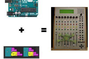
Matrix Midi Controller
A long-term project to build the ultimate hardware controller for the Oberheim Matrix 1000 synthesizer.
Become a Hackaday.io member
Already have an account? Log in.
Just one more thing
To make the experience fit your profile, pick a username and tell us what interests you.
Pick an awesome username
hackaday.io/
Your profile's URL: hackaday.io/username. Max 25 alphanumeric characters.
Pick a few interests
Projects that share your interests
People that share your interests

 uri.shani
 David Cain
 HP (@banjohat)
pcf8591