-
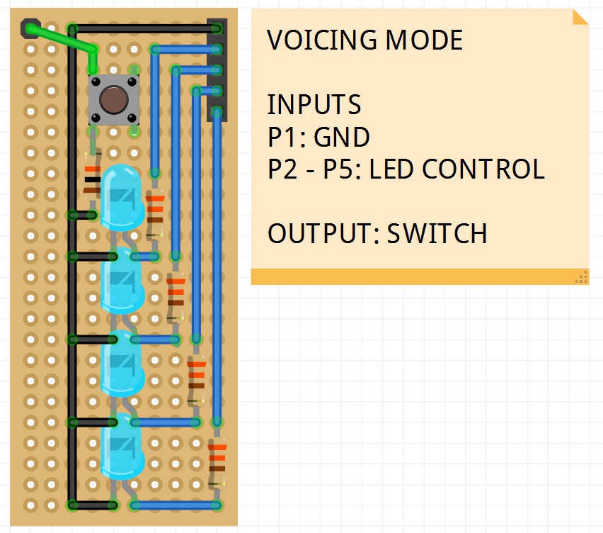
Voicing Mode and VCA
05/08/2016 at 00:26 • 0 commentsAnother simple module. A switch and four status LEDs, that's it!
![]()
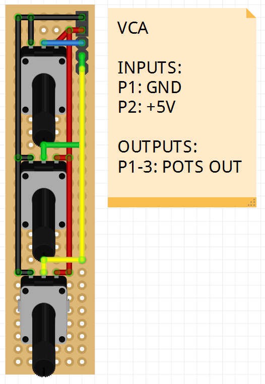
And here's the VCA design. Three potmeters isn't really complicated either
![]()
-
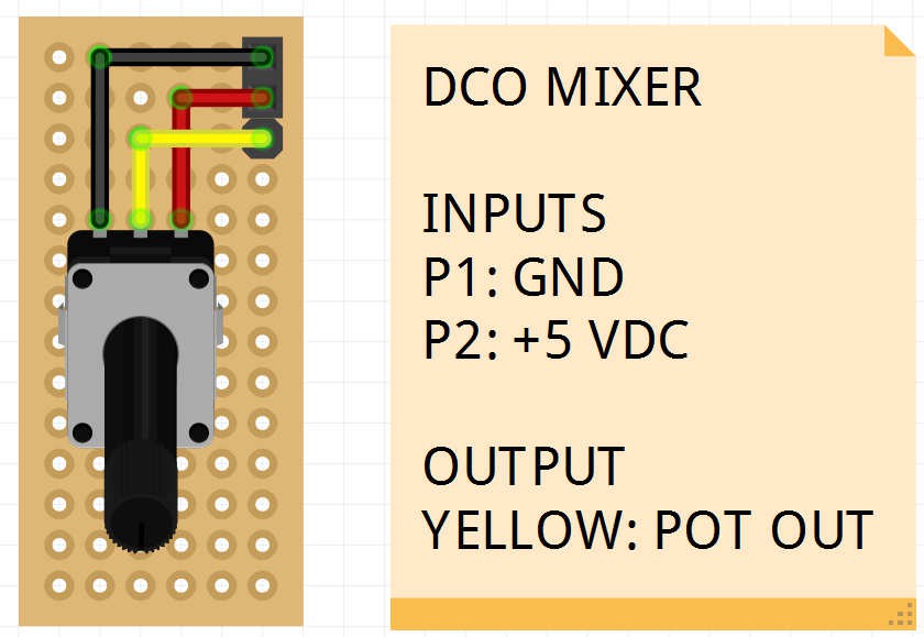
DCO Mixer
05/07/2016 at 20:59 • 0 commentsBy far the simplest of "modules" to implement... the DCO Mixer! Just one potmeter which will set the volume balance between the two oscillators. Next?
![]()
-
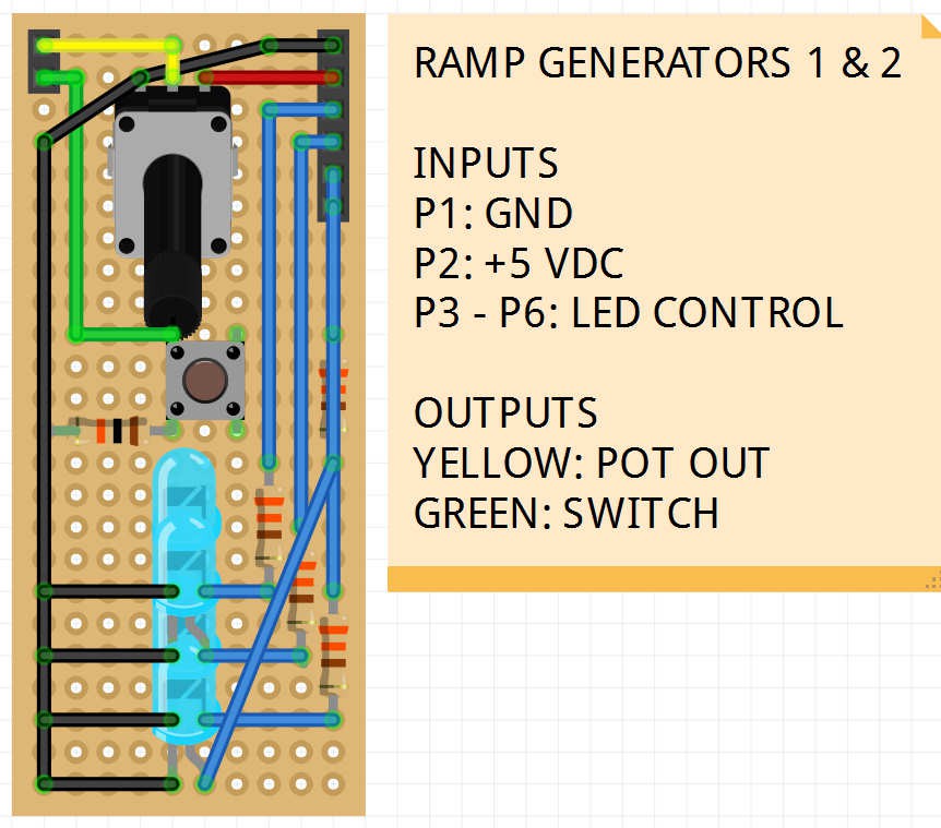
Ramp Generators
05/04/2016 at 22:06 • 0 commentsToday i received a shipment of 40 cheap perfboard PCB's in various sizes and some badly needed DuPont cables. This spurred me on to design the Ramp Generator modules. Unlike the DCO's, the Ramp Generators are completely identical and share the same PCB and panel layout.
![]()
-
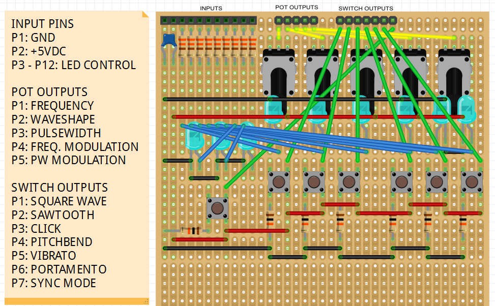
DCO 1 controller
04/22/2016 at 00:27 • 0 commentsHere's the layout of the DCO 1 controller prototype. I intend to design and build individual controller sections for all the synth "modules" like the envelopes, LFO's etc. These sections will be hooked up to the I/O expanders and ultimately the CPU.
![]()
UPDATE
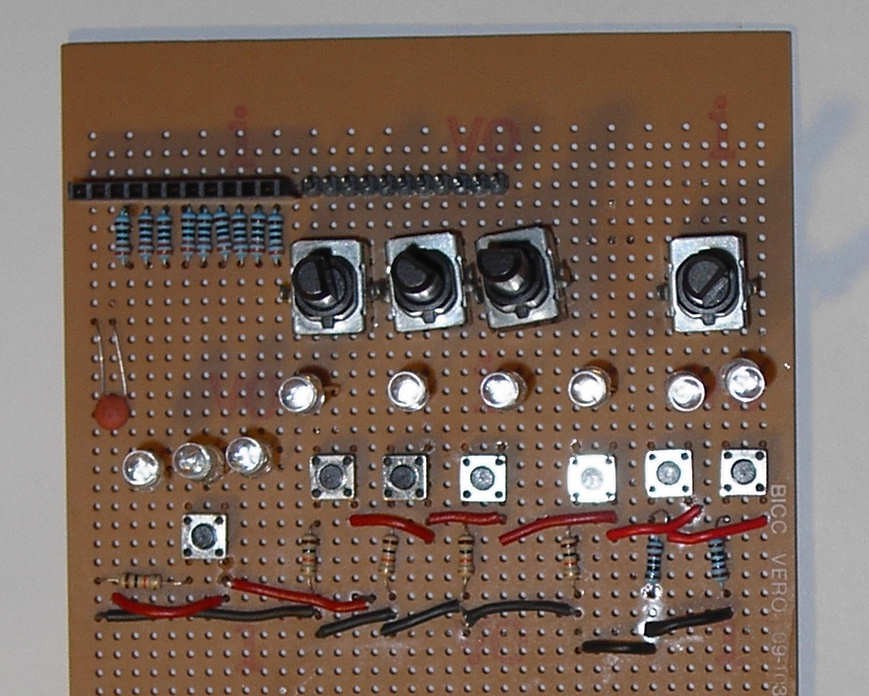
The build is coming along nicely. The stripboard traces have been cut, resistors and switches have been soldered in. But I've run into trouble with the last 3 potentiometers.. I shorted a couple of paths and for some reason I wasn't able to fix it. So I'll just have to remove and re-solder them back in place tomorrow. After that, I will put in the wiring, the I/O pin headers and finally the blinkenlights.
![]()
Nearly done! Áll that's left to do is wiring the 'outputs' from the switches and pots. Ive decided to drop one of the pots because i just couldn't get it soldered in the right spot. Perhaps i'll move it to a bit of unused stripboard real estate when i'm done with the wiring.
-
What you get is what you see
04/12/2016 at 20:08 • 0 commentsToday I received the LCD screen i ordered from China. At only $5.39 with free shipping i just couldn't resist. It's a 20 x 4 White on Blue screen with backlight and a piggy-backed i2c interface. So hooking it up to your Arduino only takes up the two pins (SCA and SCL).
But I had a lot of trouble getting it to actually display some text. I tried various libraries and examples but nothing seemed to work. After about two hours of increasing frustration I suddenly remembered that LCD screens are illegible if the contrast isn't properly set. So i carefuly turned the trimmer on the i2c interface and suddenly, as if by magic, my text appeared on the screen. Phew!
This screen will be of great value to the end product but also as a debugging tool.
-
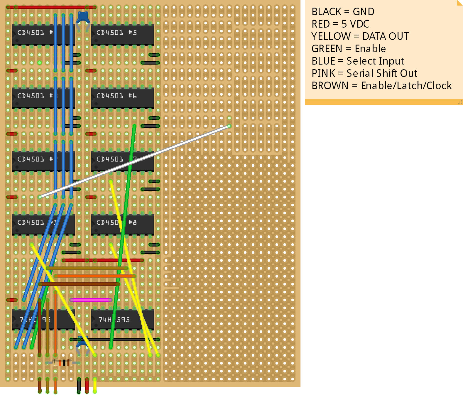
Analog Input Expansion Board
04/11/2016 at 23:50 • 0 commentsThe Matrix controller will have to feature 62 rotary knobs / potmeters so I will need to expand the number of analog input pins to "read" them all. To this end, i have designed an expansion board with eight CD4501 chips to multiplex a total of 64 extra analog input channels into one Arduino pin. This is the first circuit i've ever designed so I probably made loads of mistakes. Please leave a comment if you spot any! (I've already moved the 5V line away from GND)
Note that just a few wires have been drawn here for clarity
![]()
-
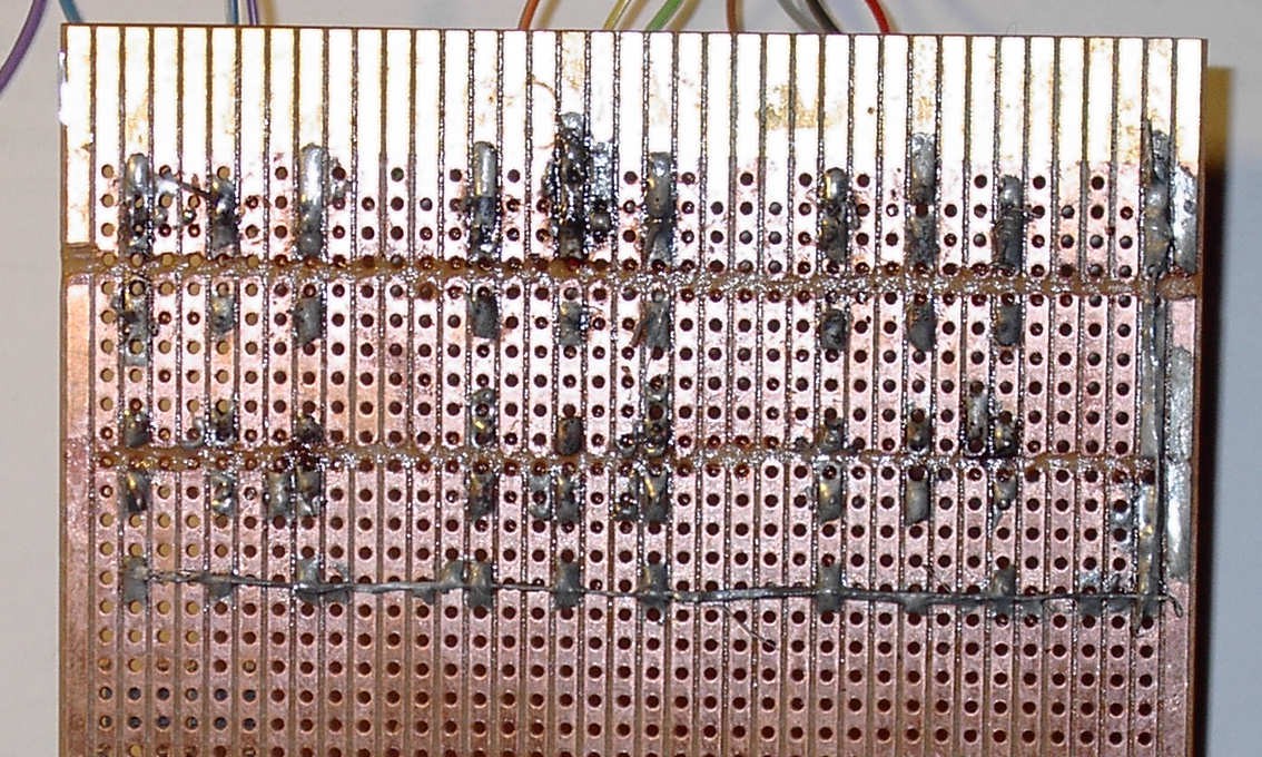
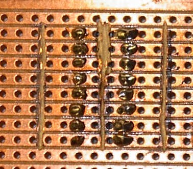
Soldering On
04/07/2016 at 21:46 • 0 commentsMany moons ago when i was a teenager I tried to solder a simple "fuzz box" circuitboard but I failed miserably and literally burned my fingers. Bad tools, no patience and a lack of guidance - no Youtube or Instructibles in those dark days - were all factors but I just assumed electronics wasn't the hobby for me.
But today i discovered that some skills can actually improve as you get older. My first attempt at soldering some LEDs, resistors and wires to a piece of stripboard came out pretty decent. It won't win any prices at a beauty contest but all the connections are correct and the board just "worked" without any re-soldering. Not bad for a trial run!
![]()
Soldering experiments were temporarily halted when i blew up my iron! I had one of those Cheap 'N' Nasty knock-off soldering stations but the plastic enclosure had started to melt so i decided to tranfer the temp control and on/off switch to a new case and knock together something much sturdier. I salvaged the spiral, attached it to a piece of wood, nailed that to a plank and presto! I turned the switch but a loud bang and a small puff of dark smoke soon made it very clear that the soldering iron had gone to meet its maker.
I have since replaced the iron but kept the home-made "station". Also read some instructions on the Interwebs. Results are quite satisfactory; nice clean joints with just enough solder and no need for flux. And my Dremel skills have improved a tiny bit as well. Eventually I felt comfortable enough to attempt to solder in some IC sockets. Lessons learned: use the right tools and RTFM.
![]()
-
Step One
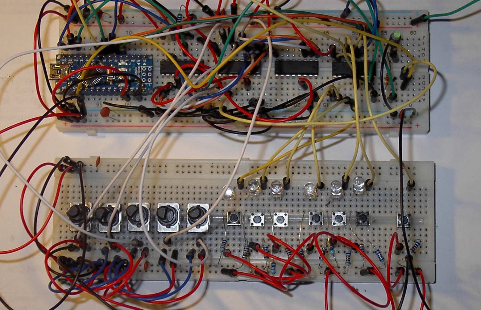
04/07/2016 at 00:05 • 0 commentsI've done some experiments to see if could extend the number of analog and digital inputs because the controller will have to feature at least 62 potmeters and almost as many switches. Quite a learning experience!
Now I'm busy with building a prototype front panel only featuring the controls for DCO1 and developing the software to read and process the input data from five pots and seven switches.
![Spaghetti on breadboard]()
Matrix Midi Controller
A long-term project to build the ultimate hardware controller for the Oberheim Matrix 1000 synthesizer.