 Dan Julio
The circuit is pretty simple. The main component is the Sparkfun PowerCell Li-Ion battery charger and boost converter. U1 is a reset detector. It drives the reset signal low when its voltage falls below around 4.4V. This signal controls the n-channel MOSFET, Q1, which does double duty: both turning off pass transistor Q2 and turning on the PowerCell boost converter when reset is asserted. Q2 is a p-channel MOSFET that passes power from the AC Adapter when reset is de-asserted (high) and Q1 switched on. It blocks reverse flow of power when reset is asserted (low). It is wired in a reverse orientation from normal use of a p-channel high-side switch so the body diode won't conduct power from the load side to the input side. R1/C1 should slightly slow down Q2 switching (although I don't think they are particularly effective with the values I used). C2 provides a bit more filtering for the PowerCell boost-converter.
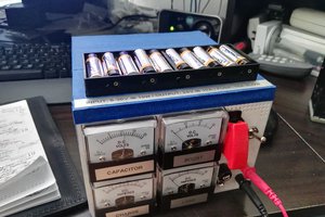
The PowerCell is capable of supplying up to 600 mA at 5V although my AP takes between 200-300 mA. It has a 100 mA charge rate. The battery is charged automatically when power is applied and there is a 2.5V low-voltage cut-off (the battery may also have a low-voltage cut-off). I'm using a 2000 mA battery which should provide a few hours of run-time.
I used the regulated 5V power supply that came with my AP, just cut the cable and wired the supply to the input of my circuit and the tail end to the output of the supply.
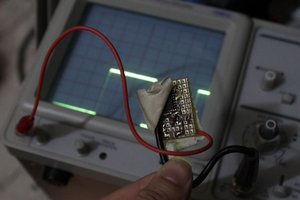
The neat thing about this circuit is that it's adaptable to many different components. I used an old ST reset supervisor but many companies make them. Any logic-level n-channel MOSFET will probably work. The p-channel MOSFET should have a fairly low Rds-on (probably 100 milli-ohms or less) and be able to carry a 1A continuous current. Other battery charger/boost circuits can also work. Just make sure that the boost circuit can be reverse driven since its output is tied directly to the 5V output line. The TPS61200 used in the PowerCell has two back-to-back transistors that block reverse current. You can test this using a lab supply. Set the supply to 5V with a low current limit (10 mA or so) and connect to the output of your boost converter. You're probably good to go if no current flows.
0%
0%
5 Volt UPS
Small low-power DC UPS for devices like WiFi access points.
Become a Hackaday.io member
Already have an account? Log in.
Just one more thing
To make the experience fit your profile, pick a username and tell us what interests you.
Pick an awesome username
hackaday.io/
Your profile's URL: hackaday.io/username. Max 25 alphanumeric characters.
Pick a few interests
Projects that share your interests
People that share your interests
 David Scholten
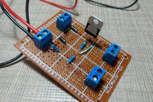
 Taste The Code
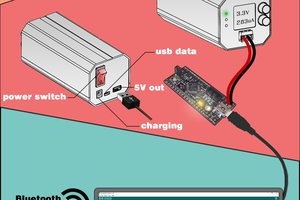
 Yann Guidon / YGDES