To make the experience fit your profile, pick a username and tell us what interests you.
We found and based on your interests.
drafts_revb.zipLayer exports for laser cuttingZip Archive - 136.98 kB - 01/09/2018 at 12:31 |
|
|
wt220-assembly.stepExport from A360step - 9.77 MB - 06/02/2016 at 06:02 |
|
|
cc-ncom-license.txtCreative Commons 4.0 Attribution Non-commercialplain - 316.00 bytes - 06/02/2016 at 05:54 |
|
Been a while since I've updated this. I'm using it lots though as a serial terminal and general embedded linux test bed. Makes an appearance with my Nixie Pipe too:
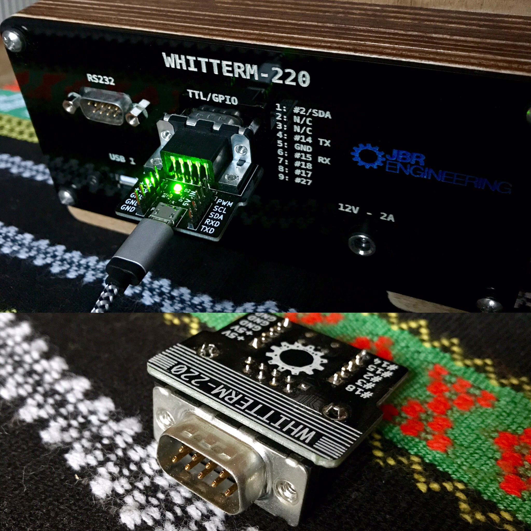
Back to this project though: through using it I realised I had the wrong gender termination for a DTE (I had a DCE), which meant using nasty adaptors/null modem stuff. I replaced it with the correct, male DB9. It works well, because the utility GPIO DB9 is female, so there is no chance of connecting RS232 levels to the wrong port.
For the utility GPIO output, I also made a simple breakout board. The board includes headers for RX/TX, I2C, PWM and 5V/GND of the Pi, an LED status and most useful of all, a micro USB to power the WT-220. This means it can be powered like a standard RPi, rather than a DC jack.
Since I've had some enquires, I've added the WT-220 to my shop. Very limited numbers will be made and it takes quite a bit of time so it is priced accordingly.
Bit of a break between updates but I've completed the first build and created video to demo the function of the terminal. Not much more to say, I'll let the video and photos do the talking.
I've laser-cut the rear panel with engraving for I/O and a handy GPIO pin-out for the TTL DB9 output. I thought since I've got 6 spare pins I might as well connect them to the Pi GPIO for use with external projects. The engraving is filled with acrylic paint using a sort of silk-screening technique.
Here's a teaser GIF of me running cool-retro-term on Arch :):

I'm only awaiting the dual USB panel mount from China before I can complete the build. In the meantime, I'm comtemplating adding battery power...
Build is coming along. I've cut the layers on the laser-cutter and glued the sections together. I opted to use glue rather than a mechanical fixing like I have in the past due to the stepped sections and to create a seamless design. The screen and Pi assembly is held from the rear on the 4th layer via the four mounting screws so can still be removed from the laminated layers. The final rear I/O layer will be held at the four corners with self-tappers.
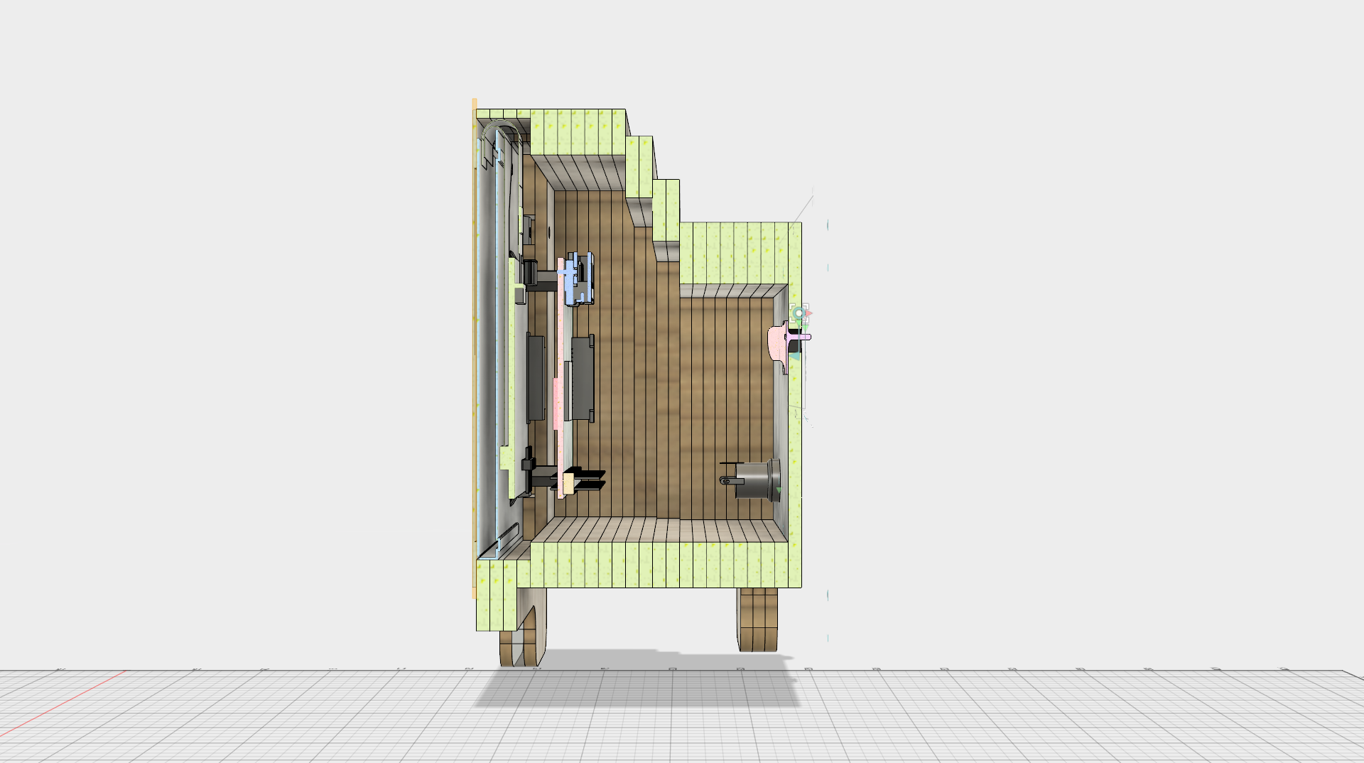
Visualising before glueing
I'm using two super bright white LEDs in parallel on each leg, which I ground down (I have 5mm in my bits box) then hot glued into the acrylic layer.
I want the acrylic layer to be illuminated but also to act as a serial activity indicator. To ensure that the line signal does not deteriorate, I'm using a op-amp voltage follower as a buffer to drive the LEDs. I've also include a GPIO line to force the LEDs on and disable the activity indicator in-case it is annoying.
Here's a link to the simple circuit on Falstad: Op-amp buffer
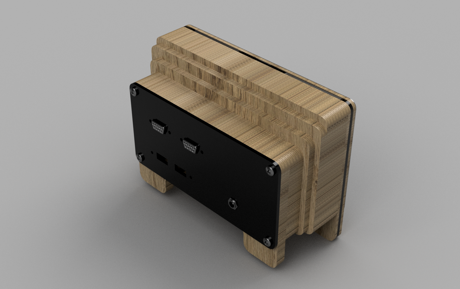
I've used this project to experiment with Fusion 360. On the whole it has been good, although I did run into a number of features I'm used to on other pro CAD packages that are missing. It seems more of a in development tool, where features are added at the request of engineers in desperation upon finding a tool missing!
Each layer of plywood is a separate 'sketch', that I export to DXF for laser-cutting. The official RPi screen and RPi are a assembly from this guy: https://grabcad.com/library/raspberry-pi-7-display-1
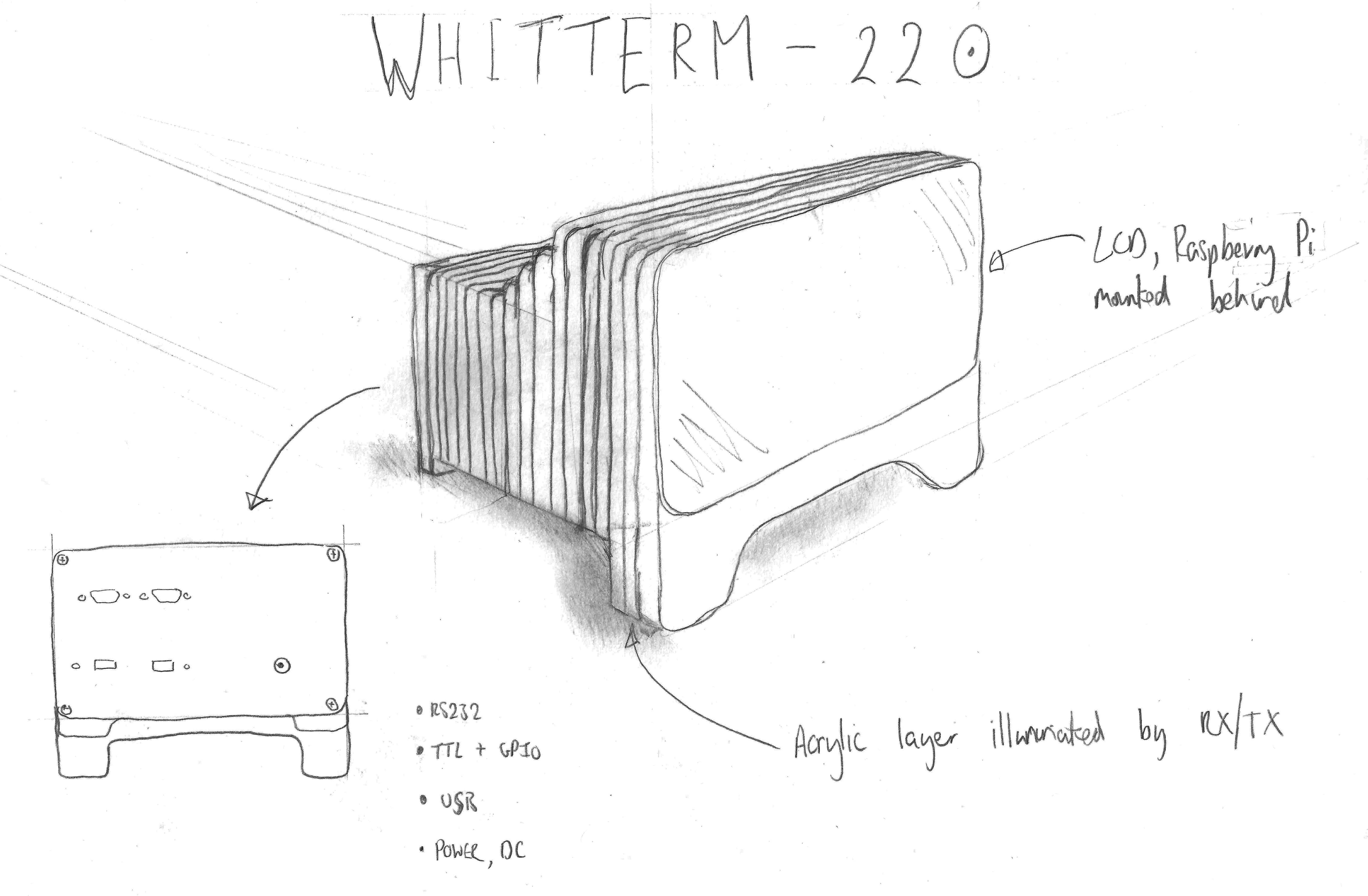
I've opted for the official screen despite being twice the price due to the flex cable connection allowing for a nice tight assembly. Having arrived I'm glad I paid the extra for what is a well engineered bit of kit. The stepped design is to minimise material usage but also aims to pay homage to an old terminal casing dropping around the CRT.
Assembly is here: http://a360.co/1qxSz4C
Create an account to leave a comment. Already have an account? Log In.
Perhaps you've solved this but you should be able to open in Inkscape or similar and change the stroke colour there. Red are engraving and black cuts.
I've uploaded new drafts anyway as I noticed some issues last one I made. I also added a README with description of colours as above.
If you're having problems, I could sell the laser cuttings only? Be interest others too. Would probably be around £50 + P&P.
John.
It's this Ajazz one: https://www.aliexpress.com/item/Ajazz-Geek-AK33-Backlignt-Edition-Mechanical-Keyboard-Blue-Switch-White-Color-Gaming-Keyboards-for-Tablet-Desktop/32620275963.html
Surprisingly good mechanical keyboard for the price and looks the part.
Im absolutely in love with this design!
I'm not a mechanical designer though, is there a way to load in the .step file and turn it into multiple .stl files for a laser cutter?
Hi Shannon. Thanks for the comment, glad you like it! I've added a 'drafts.zip' file with the .dxf exports for laser cutting. Let me know if you make one.
Become a member to follow this project and never miss any updates
 Craig Hissett
 Ryan Walmsley
 Curtis Soldano
So I finally re-found this cause I want to actually send it to Ponoko and have them create the pieces for me, unfortunately there is some issue with the color of the stroke, complaining it is red when it needs to be blue or something. Is there a simple program I fix this in?