Although there are more and more studies related to microbial fuel cell, this subject is still relatively unknown among the general public. This projects aims to make this technology accessible to everybody by providing open source access to the experimental prototypes we made. These prototypes are made of affordable materials and are easily reproducible, allowing opening to a citizens' approach. Everyone is then invited to appropriate the scientific experiment and to discover new applications.
Our team is composed of a designer and an electronic engineer who started with very little knowledge on the subject of microbial cell. It is therefore, driven by our curiosity and our desire to see the possibilities of this technology, that we started exploring, with our complementary areas of expertise, this subject leading to several more or less prospective applications.
The project is also a collaborative experience, since our lack of knowledge on this subject has led us to establish a network of contact, allowing the project to develop.
How does it work?
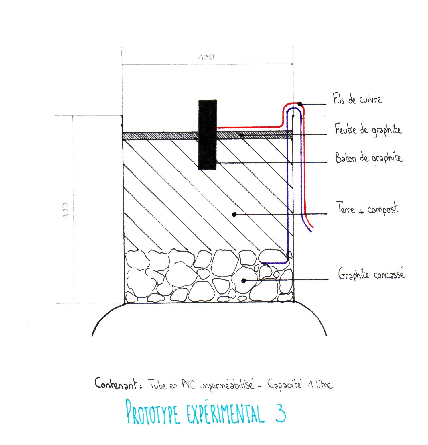
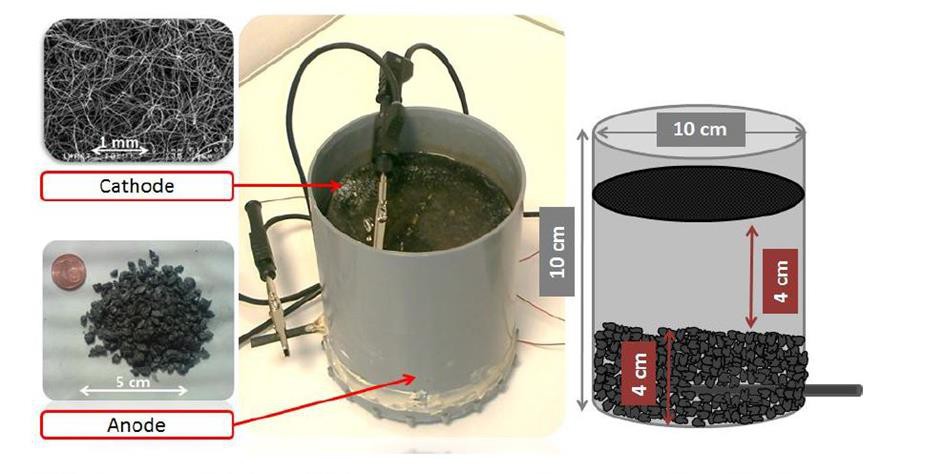
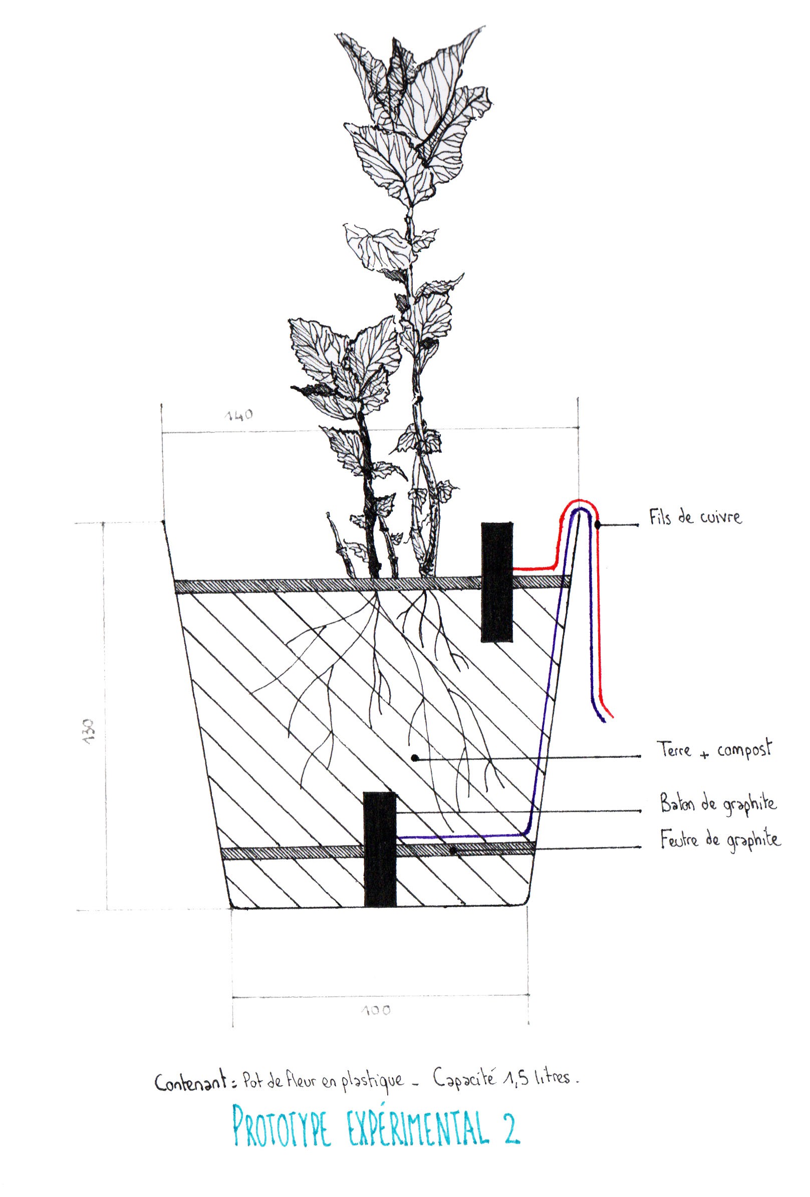
At the bottom of the pot, the soil is poorly oxygenated (anaerobic), and provides good living conditions to electro-active micro-organisms (geobacter, etc…). These micro-organisms “eat” the organic matter released by the plant and produce H+ ions and electrons, which are transmitted to the anode. On the cathode side, the electrons combine with oxygen and H+ to produce water. The H+ ions are transmitted from the anode to the cathode through a Proton Exchange Membrane (PEM), or a salt bridge.
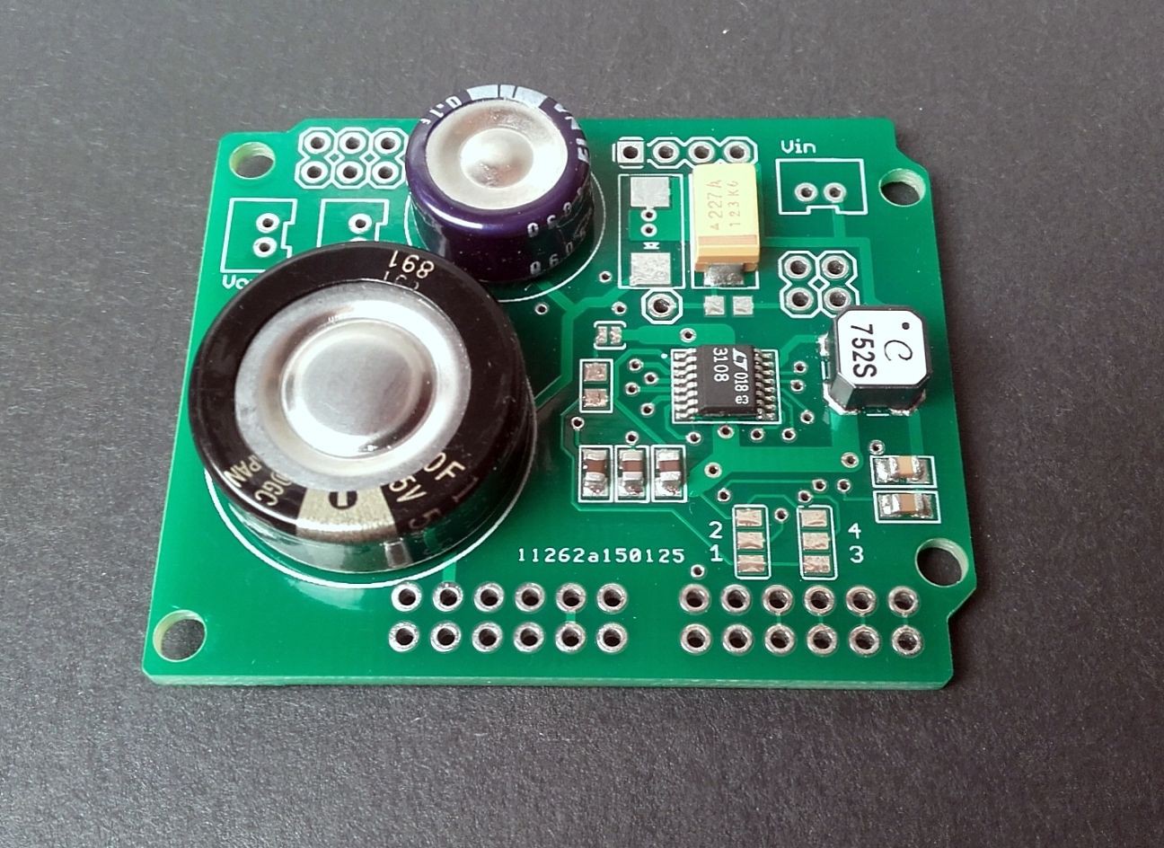
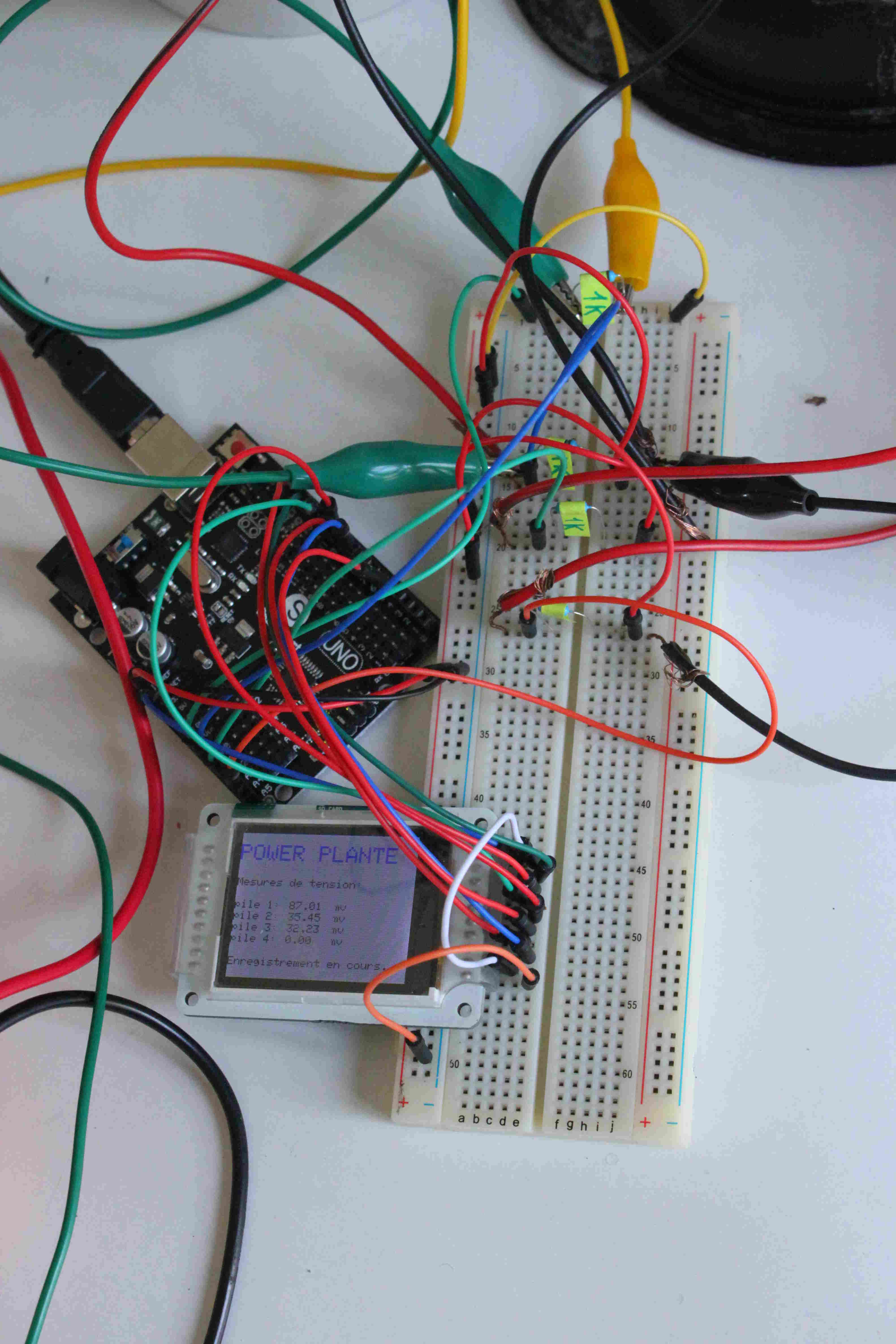
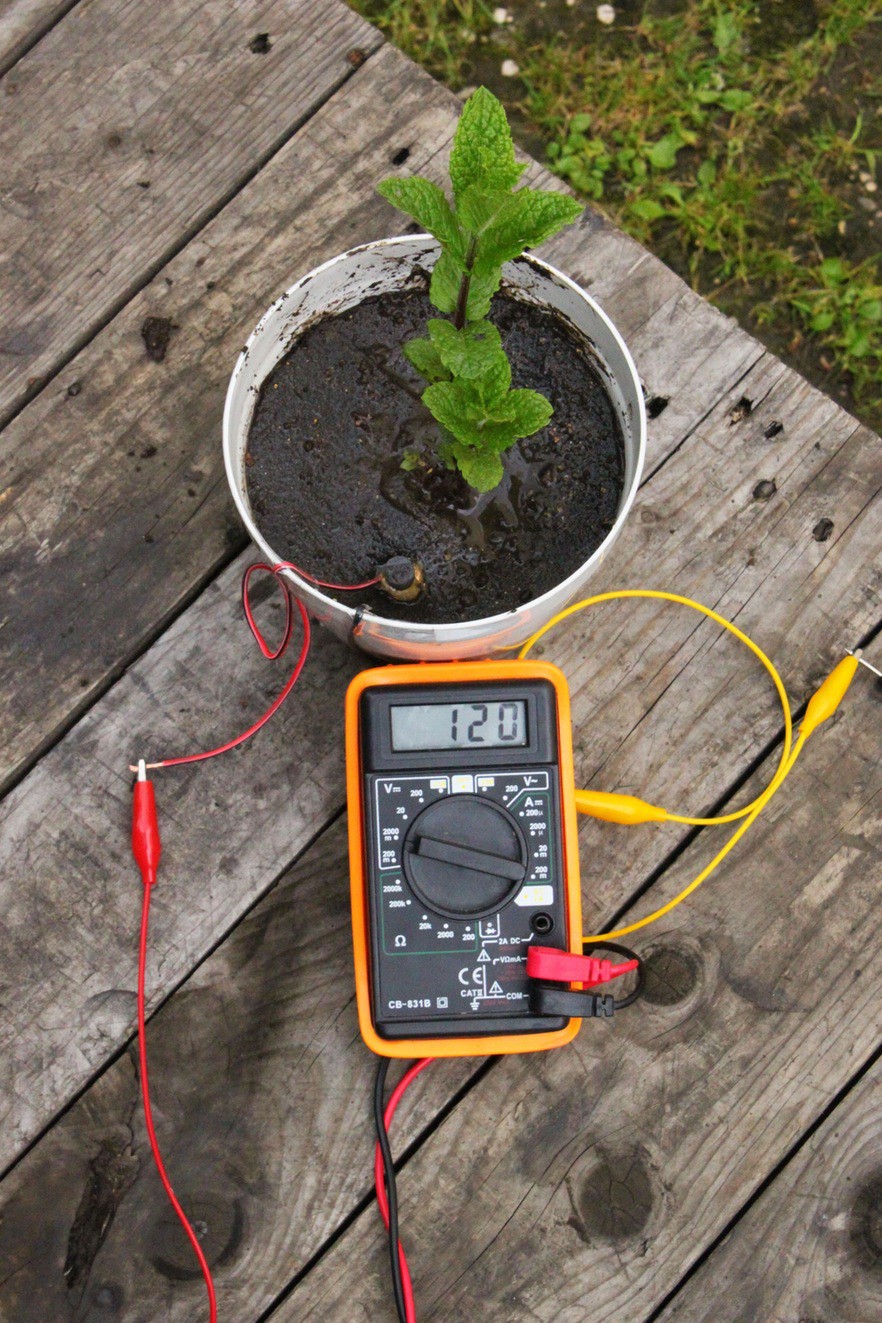
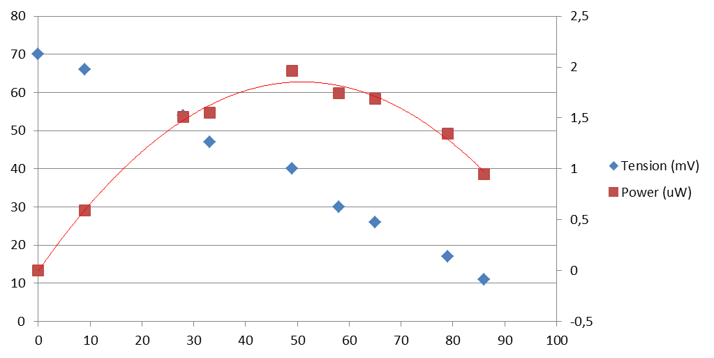
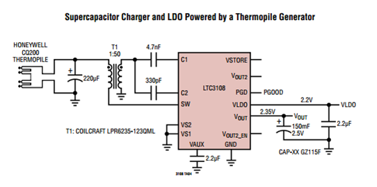
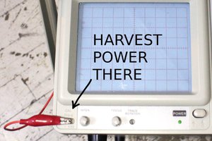
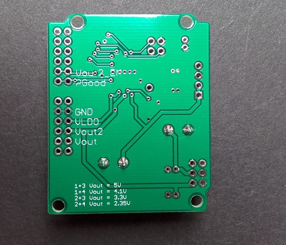 But after cabling it to our Mint MFC, big deception L… When plugged to the card, the voltage at the terminal at the MFC dropped from 500 mV to 20 mV, and we only got an output of Vout =100 mV, and Vstore = 40mV across the storage capacitor…


 Yann Guidon / YGDES
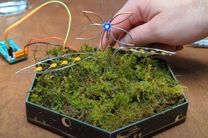
 Guru-san
 c.Invent
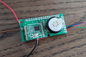
 strange.rand
Hi Ever!
Yes, actually we are starting to design schematics and PCB, it would be great to have your help! I contact you in MP.
Johann