 danjovic
Introduction
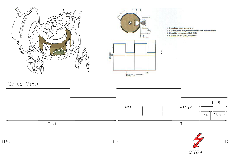
In a typical ignition system the high voltages necessary to burn the fuel are generated by a coil which is driven by a switching mechanism linked to the crankshaft. The switching is mechanically synchronized in order to provide the spark at the right moment, so the fuel has time to burn and push the piston with the power of the explosion.
Such process involves three important time related parameters: Coil charging time, Fuel burning time and Engine speed. The burning time also depends upon the load on the engine which is perceived by the vacuum in the admission chamber (manifold).
One of the problems of the ignition system is that both the charging time and the fuel burning speed are nearly constant allover the engine speed rate, which required some compromise solutions even in the systems with electronic ignition:
- The coil charging time was set about 50% of the time (Dwell time) and the current is limited by the coil internal resistance (a series resistor is also used in some systems). The current limitation implies in a spark with low energy, specially during startup where the battery voltage can drop down to 8 Volts.
- The burning time is changed according to the engine speed by the use of mass and spring mechanism (centrifugal advance) and with a vaccum capsule (vaccum advance). Both mechanisms provide an angular displacement that is tuned to match with the timing required by the engine, but the dispersion of parameters specially on the springs used in both mechanisms is high and you can't find spare/alternative springs to buy, only assembled parts which in turn are physically alike but have different part numbers and no information available.
The present project tries to address both of problems by providing precise timing of both coil charging time and spark release with the minimum addition of parts and adds some safety features.
Design
The circuit was designed to stand between the original sensor and the coil. It consists of a Micro controller, a MAP sensor and and a Power Transistor.

At the TDC the microcontroller measures the time taken in the previous cycle (90° of the distributor shaft). Then the software assumes that the timing of the next cycle will be close enough from the previous cycle, i.e. it assumes that the timing between two cycles is nearly constant (the rate of change can be considered in the calculation using a filter or a PID calculation, tough). Then it adds the base timing with the vaccum timing to calculate the moment of the spark. From the Spark time it subtracts the coil charging time and calculates the moment of the starting of the charge. Both times (Start of Charge and Spark) are programmed in two timers which in turn will generate an interrupt that will turn the coil on and another that will turn the coil off, thus generating the spark that will generate and explosion which will peak a bit after the TDC.
Software Architecture
The basic software architecture consists of a main loop and several interrupts.
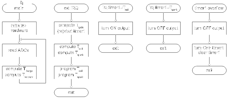
The main loop is where the ADCs are read. One of the ADC channels reads the car battery voltage and use the value to calculate the coil charging time. Another channel is used to read the vacuum signal coming from the MAP sensor and provides an additional time for burning the mixture.
The external interrupt is used to measure the time it take for the engine to turn 180° which is sensed every 90° on the distributor shaft (which runs at half speed of the engine). From this time it is subtracted the base time (around 2ms) added to the contribution from the vacuum sensor and resulting in the time Tspark which is the moment where the spark must be generated. Then, from Tspark is subtracted the coil charging time and the result is Tcoil. After the calculation both Tspark and Tcoil are programmed in the compare registers.
At a time equals Tcoil a compare interrupt is generated and which turns on the power transistor thus starting to charging the coil.
At a time equals Tspark another compare interrupt is generated and the power transistor is turned off thus generating a spark.
The function of the Timer1 Overflow interrupt is to turn off the coil when the engine is idle or below a given speed. It also turns off the counting of the timer to prevent misfires that would occur when the engine is starting.
Hardware Architecture
The basic hardware architecture is composed of a micro-controller, a voltage regulator for the micro-controller, another voltage regulator for the external sensors, a power transistor and a protection stage composed of a flip flop and a current sensing device.
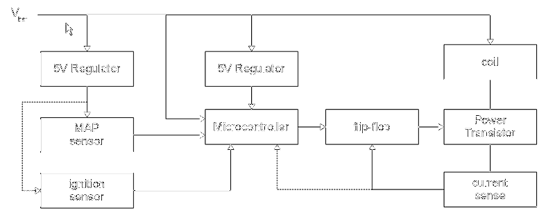
As everything that ought to be connected to a vehicle, all inputs and outputs shall be designed to stand with a short to the GND and a direct connection to the battery (+12V), thus the MAP sensor has it's own power supply with short circuit protection and a series diode to prevent over-voltages to burn the regulator. The analog input is clamped to +5V and to GND through a couple of diodes and the current is limited by a series resistor though its resistance is small enough to not interfere with the measurements. The same scheme of protection is present on the pulse (RPM) input.
The output transistor is not turned on/off directly by the micro-controller but through a D type flip-flop on which Reset input is connected to a current sensor composed by a low resistance shunt and one NPN transistor. Above a given limit of current the voltage over the resistor will exceed 0,6V and the transistor will turn on resetting the flip-flop and turning off the power transistor. Such excessive current might be caused by a wrong connection of the output to the Vbat line or by wrong timing. One possible improvement would be to use the reset signal from the power sensing transistor to trig a pin or interrupt on the micro-controller thus providing a way to learn the correct timing for an unknown coil. Another improvement would be to use the micro-controller analog comparator instead of the transistor but the protection would need to rely totally on the software since the comparator output is not available in a micro-controller pin (unlike the PIC comparators).
Timing
The micro-controller runs at 16MHz by the use of an external crystal. The internal oscillator not used due to the large variation across the expected operation temperature range (10°C to 80°C). The prescaler value used is 64 which means that each count takes 16MHz/64 = 250KHz => 4us. It is now possible to calculate all timing in terms of 4us counting units
The engine speed, measured as the interval betwenn half engine turns, is within the range of 50000 counts @ 150 RPM down to 1042 counts at 7200 RPM.
The base advance (Burn time) for the VW air cooled advance is 7.5° at 900RPM which takes 1,4ms or 350 counts.
The vaccum advance is being considered from 0 to 1,5ms for a range of 60 to 270mmHg which means 0 to 375 counts.
The coil charging will depend upon the coil parameters as well as the battery voltage. For a given coil and considering a fixed peak current such time can vary from 4,13ms @ 8Volts to 1,71ms @ 15,5Volts which in terms of countings can vary from 1033 to 429 counts.
At last we must respect a minimum time for the spark to cease before start charging the coil again, Such time is in the order of 1,5ms.
The times involved are summarized on the table below
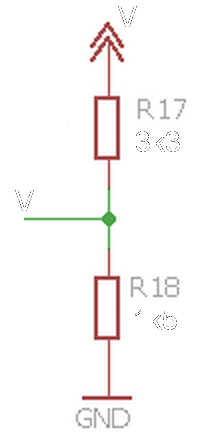
Battery Voltage measurement
The battery voltage is measured by using a voltage divider composed by R17 and R18. The values of both resistors have been chosen to allow the measurement of up to 16 volts before saturating the ADC input. The firmware converts the useful range (8.0V to 15.0V) into a 4 bit value to select the base coil charging time from a table of 16 entries.
Manifold Air Pressure measurement
The measurement of the manifold air pressure (vacuum) is performed by a Magnetti Marelli PRT 03/04 MAP sensor which provides a linear voltage from 0 to 4.5Volts in response to a vacuum signal from 17 to 105kPa.

The usable range start at the low limit, 17kPA and ends at 270kPA which corresponds to 250mV to 722mV or 51 to 148 'counts' when read by the ADC with 10bit resolution.
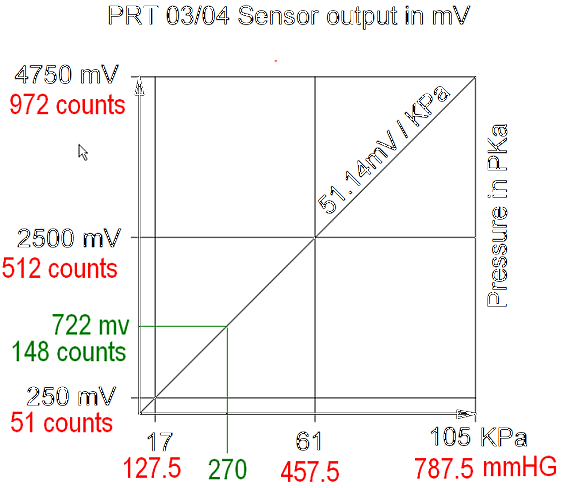
The advance will increase as a function of the manifold air pressure ranging from 0 to 1,5ms at the maximum pressure.