 danjovic
First schematics, fresh out of the oven. Used only one voltage regulator, though.
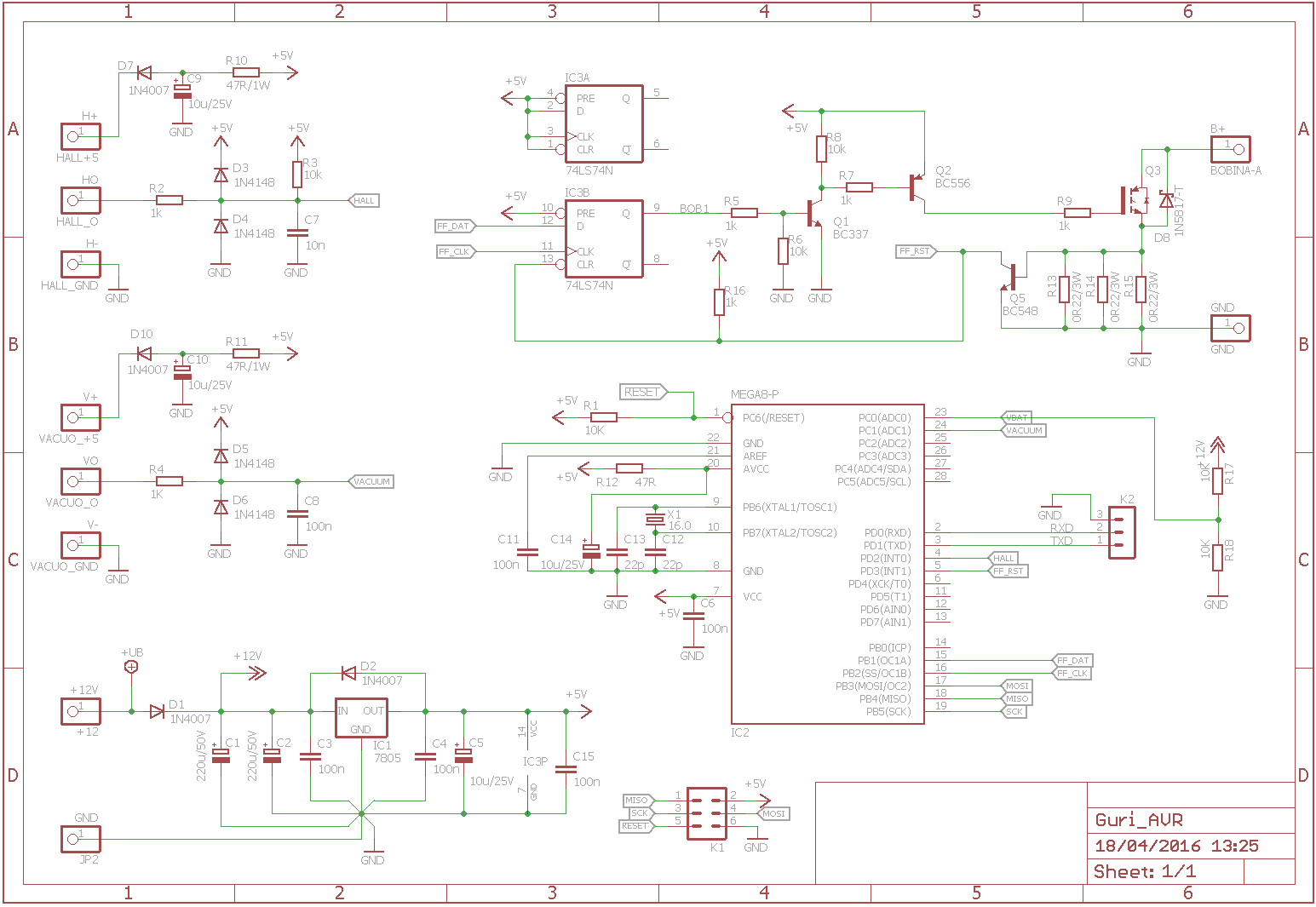
A project log for Guri: Ignition Controller for Air Cooled Engines
Ignition controller for VW air cooled engines.
First schematics, fresh out of the oven. Used only one voltage regulator, though.
Discussions
Become a Hackaday.io Member
Create an account to leave a comment. Already have an account? Log In.
Hi, K.C. thanks for commenting. This particular IGBT (IRGB14C40) already have the pulldowns but I'll keep an eye on the turn off time. As for the series resistor in Q5 base I missed that when I borrowed the protection circuit from mr. Chan's power incutor tester. I will also look for the MIC291xx regulators. Thanks!
Are you sure? yes | no
You'll need to have a pull down for Q2 output. Unlike a BJT, the gate of the IGBT (?) is like a MOSFET so you'll need a way to discharge the huge gate capacitance to turn it off.
Probably a good idea to have a series resistor in the base of Q5 as it'll take a long time to turn off the IGBT and until then the B-E junction might get too much voltage. You should add a RC filter to catchglitches.
I highly recommend the MIC291XX LDO for automotive environment. They have very good input protection against over voltage (load dump) and reverse voltage (jump start with the wrong polarity).
Are you sure? yes | no
Hi, K.C. thanks for commenting. This particular IGBT (IRGB14C40) already have the pulldowns but I'll keep an eye on the turn off time. As for the series resistor in Q5 base I missed that when I borrowed the protection circuit from mr. Chan's power incutor tester. I will also look for the MIC291xx regulators. Thanks!
Are you sure? yes | no