 TK
TKI enlisted the help of my friendly local Alex (TM) and we got to work tracing the PCB and figuring out how the car controls steering and drive. Initially we had a lot of luck and I quickly found a way to control steering and drive; these early gains were quickly scuppered as my youthful overexuberance led me to make some wiring errors which let the smoke out. To get the whole story, check out the video! The picture below illustrates the basics of what we did to control the car.
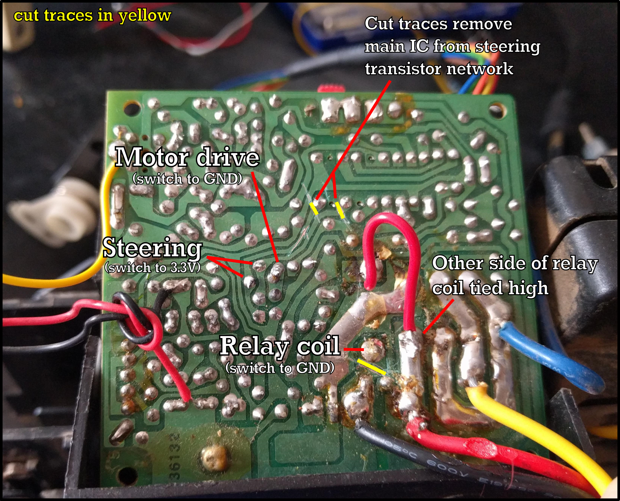
The motor drive was easy; there's a big fat NPN FET on a heatsink (not pictured; other side of the board) that switches the motor on or off. I found a nice convenient point on the board that triggered this FET when I tied that point to ground, so it was as simple as hooking up a little NPN BJT (BC547) to the Raspberry Pi to control the motor drive. Forward and reverse of the motor is controlled by the relay (not pictured; other side of the board) which swaps the polarity of the motor leads depending on which direction you wish to go. To control this, I cut a trace connecting the coil to ground, and tied the other side of the coil high. I was then again able to pop in a BC547 to switch the relay from the Raspberry Pi.
At this stage, we have motor drive in both forward and reverse. So far, so good. This is when things started to fall apart.
I was really excited when I started trying to figure out the steering. From visual inspection of the top of the board, I saw a series of pairs of transistors, three pairs of two in total, that I figured were a little network used to control the steering motor. I then quickly found two pins on the main IC; one went high when I held left on the RC transmitter, the other went high when I held right. When you're not steering, the car self-centers its steering which is great, too. So I figured I could simply try dragging those pins high myself and see if the steering worked. And it did!
However, I noticed that manually pulling these pins high was drawing 15mA, which was way too much just to switch on a few transistors in the network. I determined that if I cut the traces connecting the steering network to the main IC, I could still activate the steering left or right, but the current draw was much lower. It still self-centered, too. So I was set!
It all fell apart when I connected these steering pins to the Raspberry Pi with a couple of PNP BJTs (BC557s). First, I still had the transistor's emitters connected to the 2.8V (weird supply voltage right?) line on the RC car's PCB instead of the RPi's 3.3V line. I also forgot to tie the grounds of the RPi and the RC car together, so the transistors were all over the place. And finally, I forgot that PNPs are switched on by pulling the base to ground, the opposite of NPNs, so I was switching both the left and right transistor networks on at the same time. I believe it's a combination of these factors that led to the ensuing tragedy...
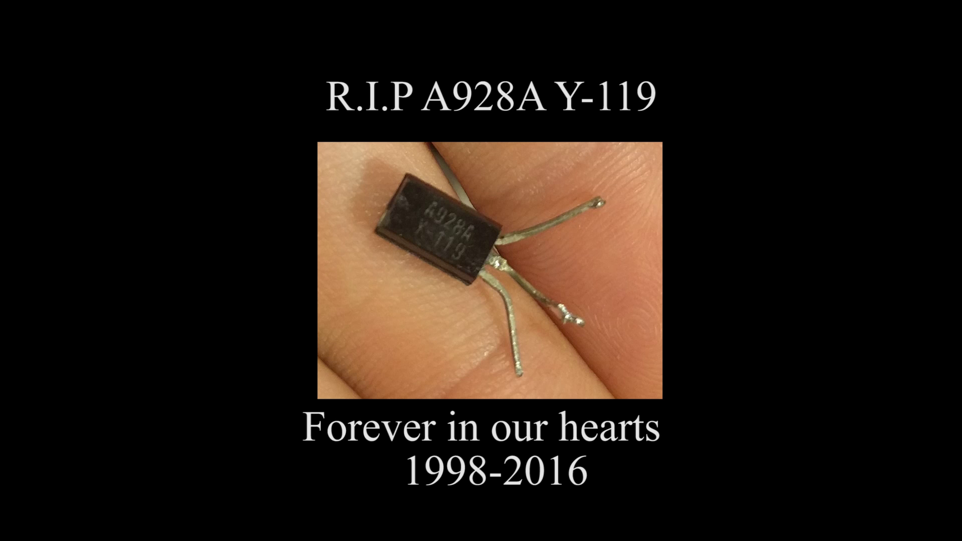
I let the smoke out, and for my folly, a brave PNP died in my arms. After much desoldering and transistor testing, I determined that this was the only verifiably dead transistor, but I replaced a few on the board anyway. These A928As in particular are high current types rated for 2 A, which I replaced with BC557s I had on hand which I think are only rated to something like 100mA. I got the steering twitching again but it still wasn't functioning right. Eventually I decided to rip out the main IC after finding some strange voltages on it, and... success! I could steer left and right again by manually applying voltage to the steering pins. However, I have lost the self-centering capability which was controlled by the main IC reading the steering encoder.
While I did restore some functionality to the steering after so thoroughly blowing it up, I'm currently torn between two options. I could push on and wire the steering encoder to the RPi and code it to self-center, but I'm at risk of the underspecced replacement transistors burning out and the PCB pads and transistor leads have all seen better days and will probably fail under vibration fairly easily after I replaced them 2 or 3 times each. I'm pretty tempted at this point to sub in a servo instead, driven from the RPi's hardware PWM line. For now, that's a question for another day.
Thanks for reading and keep an eye out for the next update on TKIRV!
Discussions
Become a Hackaday.io Member
Create an account to leave a comment. Already have an account? Log In.
Nothing gets you thinking like reverse engineering, good seeing you get over most of the hurdles. I can't help but feel you nearly would be better off grabbing an esc and servo and driving these from the pi instead trying to repurpose the existing control board.
Are you sure? yes | no
Yeah, had everything gone to plan, using the original control board would have been perfect but there's always unforseen issues... :P
I think I'll still use the original board's drive motor control because that works to my taste and there aren't any ESCs that are good to use with the RPi that I like out there but I'll probably replace the steering with a servo, yeah.
Are you sure? yes | no