 Ryan Bailey
Update: Initial programming was a modest success. There is still some temperamental behavior to work out with the programmer - some searching suggests that termination/reflection issues on the data line sometime cause programming to fail. Still, I was able to load and run a simple LED blink program:
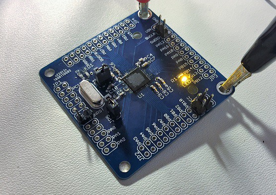
It's been a busy couple weeks but I finally found the time (and the correct parts) to finish assembling a couple of the microcontroller testing boards that I cooked up last month.
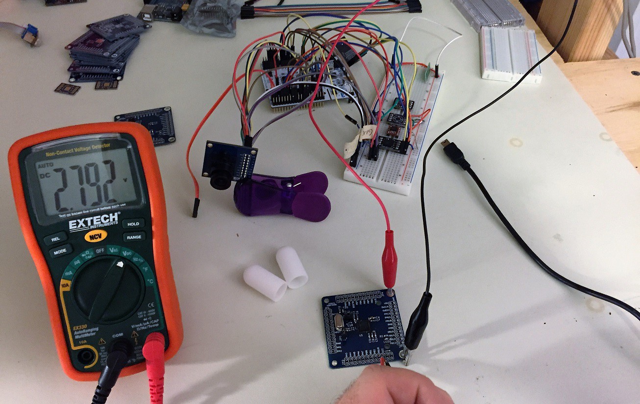
Also pictured: complete mess-of-wires version of the final system. The main voltage rail is 2.8V, regulated from 4-5V input, as required by the camera.
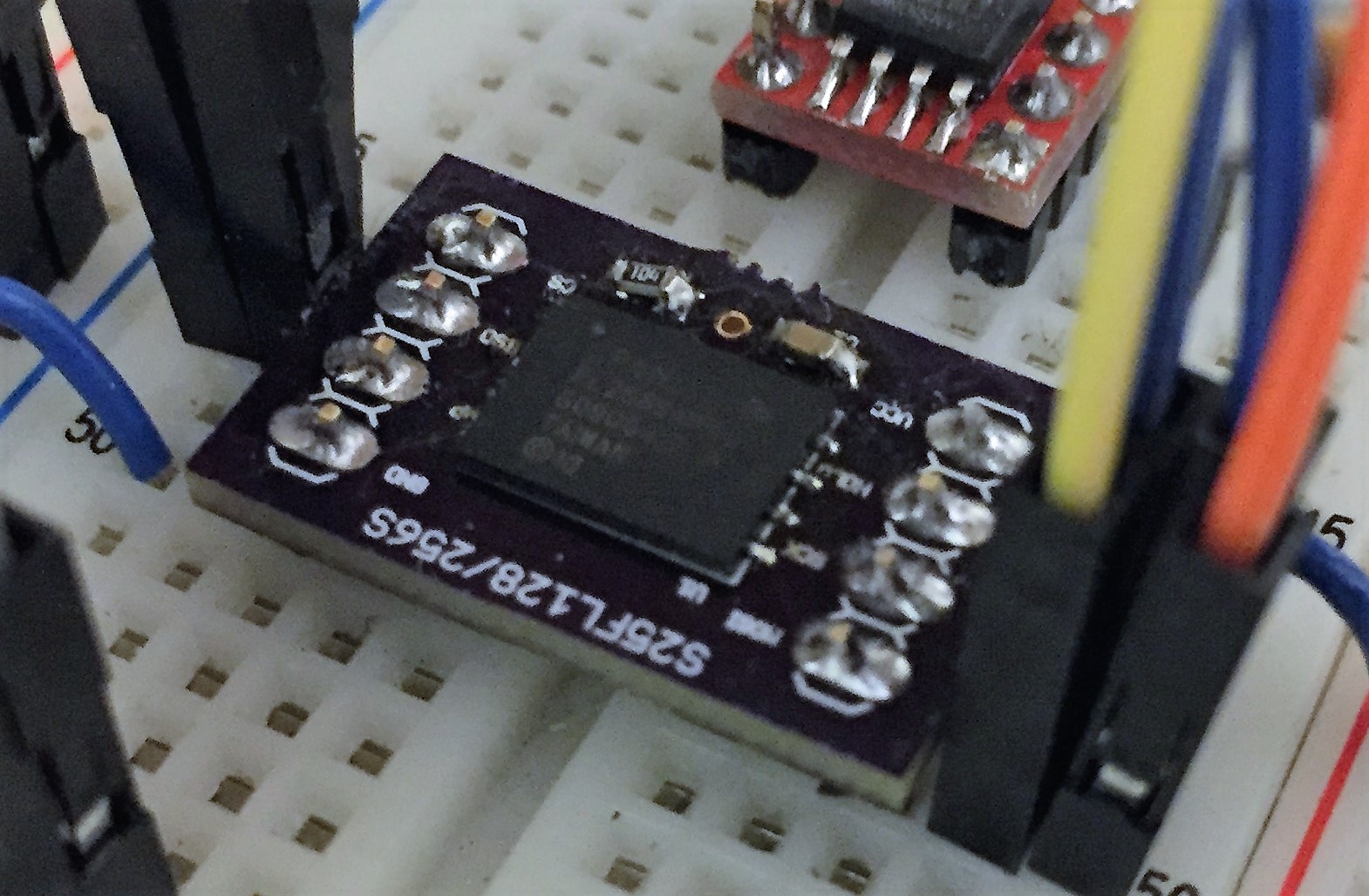
Also notable is the quick proto board I threw together for the 256Mbit flash device. It's a slightly weird-looking package so I wanted to try a standalone board before 100% committing it to the final design.
No magic smoke so far. Programming tests coming soon.
Discussions
Become a Hackaday.io Member
Create an account to leave a comment. Already have an account? Log In.
I usually have VIO and GND next to the SWD signals in my layout and use twisted pairs from cat5 patch cable organized like this: (SWCLK/GND),(SWDIO/VIO) to maintain controlled impedance as these are high speed signals. Never have an issue with the debuggers or the different ARM chip series in my projects.
Are you sure? yes | no