 Yann Guidon / YGDES
I wouldn't have thought about this project if I wasn't actively developing circuits using Germanium parts. They have a very low switching voltage, around 0.2V, unlike the silicon diodes (0.6 to 0.7V). This makes energy harvesting possible and this was essential in the age of crystal radios...
This low drop is also useful to extract small current from low voltage signals. Germanium diodes (the "detector" type) can't handle much current (20 to 40mA peak max) but there the losses are minimal: if we consider the first third of the charge pump (made of D1 and C2), the efficiency is about 90% (0.2V of drop for a 2V signal).
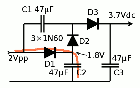
This first stage of "simple rectification" is necessary to provide a first "base" voltage of 1.8V for the actual charge pump. The actual elevation of voltage comes from C1 but it can't work if it starts from 0V.
Let's now consider that after a few cycles, C2 is fully charged. When the input is low, C2 can't discharge through D1 (we'll ignore the leakage currents which was barely measurable in a https://hackaday.io/project/10698-clockwork-germanium/log/35373-germanium-diodes)
So there is a difference of voltage between the electrodes of C1. When a rising edge comes, the difference remains, which "pulls" the anode of D2. Since this is the conducting direction, current flows though D1 and D2, effectively charging C1 (and C3 through D3, the last recitification stage).
When the input signal falls, D3 prevents the discharge of C3 and D2 prevents the current from going back. Charges are trapped at 2× the input voltage !
Discussions
Become a Hackaday.io Member
Create an account to leave a comment. Already have an account? Log In.